Cool.
Yep, and it was kinda’ necessary learning in order to experiment with @Robert.Wall’s excellent suggestion which I finally got around to trying out:
That turned out to be surprisingly easy to implement on the F303 (probably all the families with multiple ADCs I suspect). The approach I took is to set up one of the timers (TIM8) in one-pulse PWM mode which allows you to output a precisely timed pulse. I’ve configured mine to generate a pulse of anywhere from 1usec to 1msec.
You then internally route TIM8’s output to all the ADCs via TRGO2 and tell them to trigger on that signal. Set one to trigger on the negative edge of the pulse and other to trigger on the positive edge of the pulse and voila… you can precisely control the time shift between the ADCs starting. Having done so, they stay lock-step at that displacement because they’re all running off the same clock.
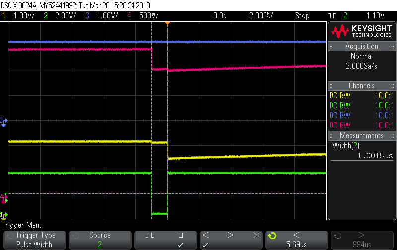
In the following scope pictures, Green is the pulse output, Red is an analog pin mapped to first channel in ADC2’s sequence, Yellow is the same for ADC3. There’s no requirement to run the pulse output to a pin as it all get routed internally, but it makes debugging a lot easier. The analog pins just have 1M pull-ups again to ensure their start-of-sample is clearly visible.
1 usec displacement
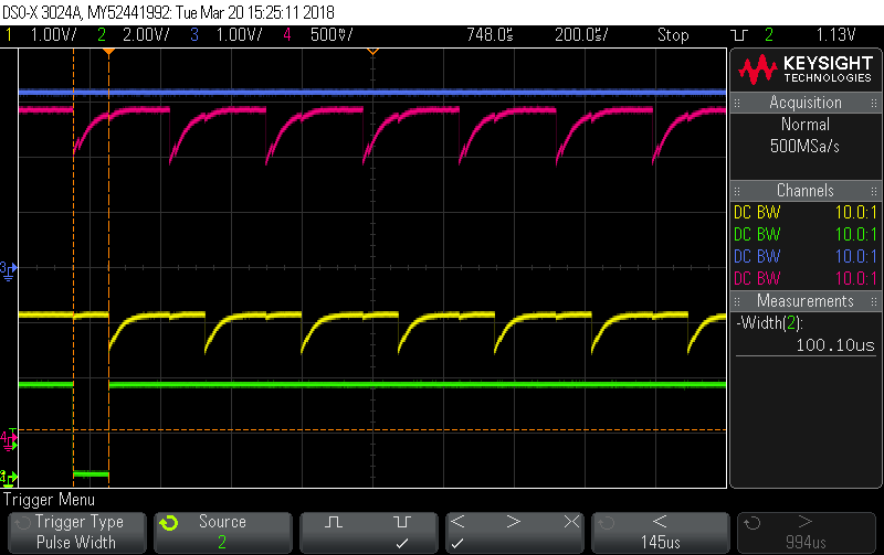
100 usec displacement

1 msec displacement.
You can see in that last one ADC2 has got almost 4 samples in before ADC3 starts.
The sampling maths for this one is:
1 conversion takes 614 cycles @ 36MHz is 17 usecs
16 conversions per sequence takes 272 usecs
That gives a per-channel sampling frequency of 3.68 kHz.
50 sequences per half buffer gives an interrupt arrival rate of 13.6 msecs per ADC
I figured this time I should actually feed it a signal and look at the results to see it was doing as intended. I wired the signal generator to both input pins (so they’re both sampling the exact same signal) and generated a 50Hz sinewave. Here’s what I found in the dma buffers at the various timeshift settings:
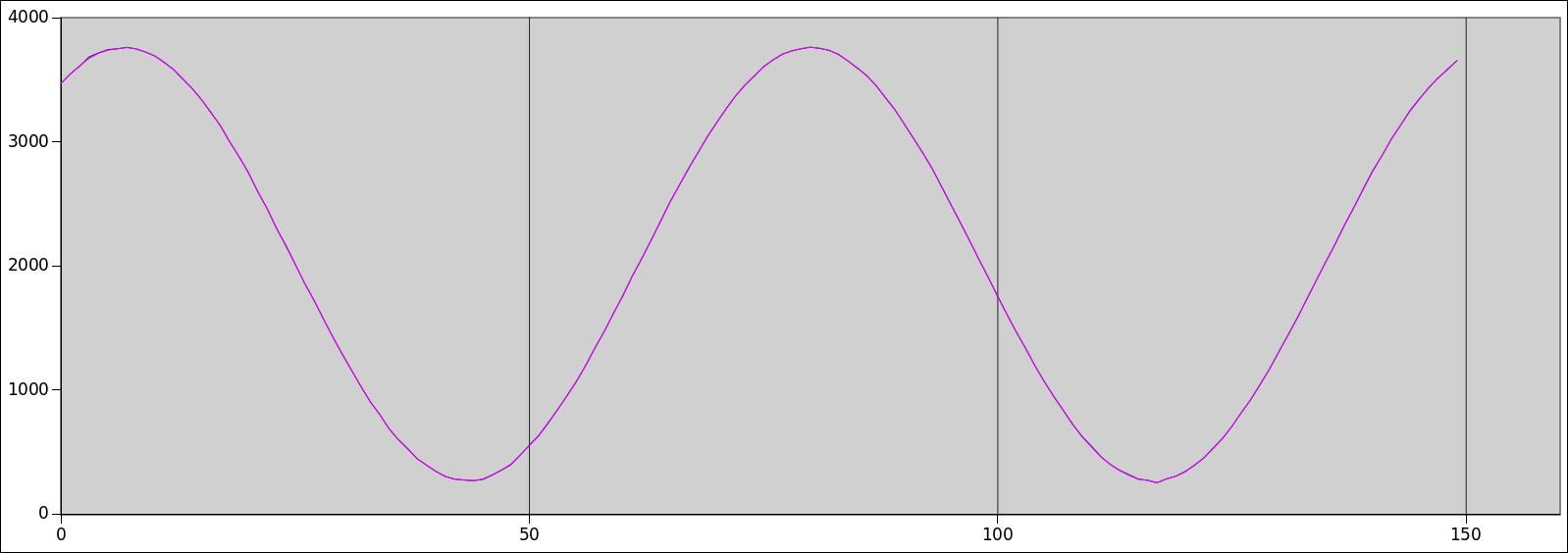
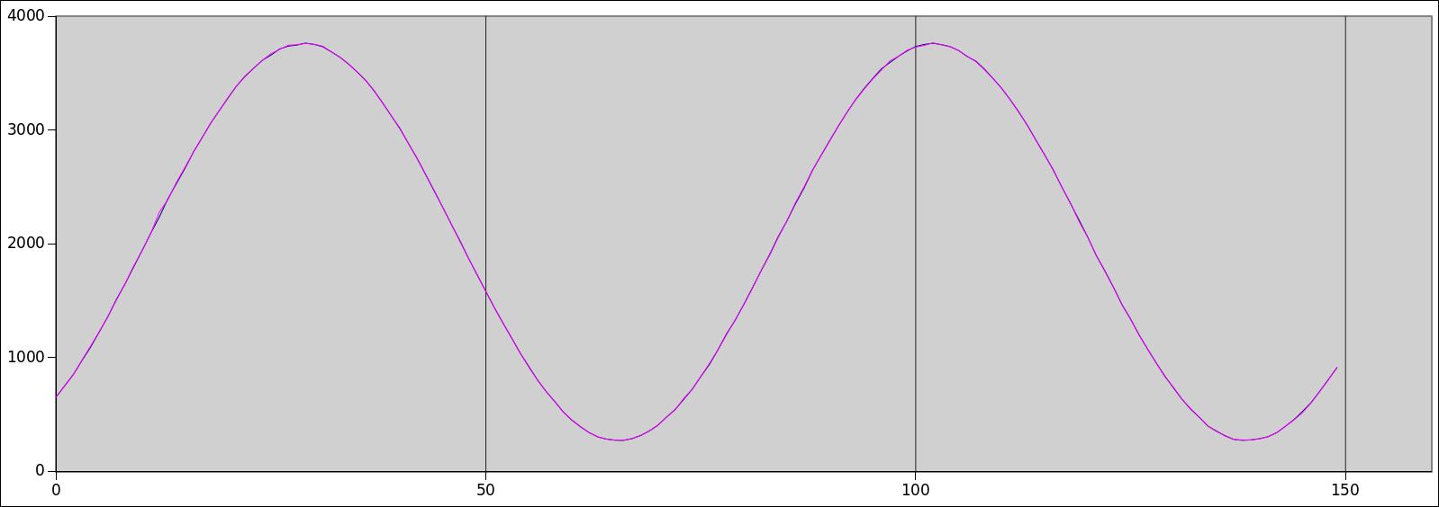
0 usecs shift.
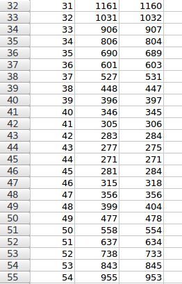
Those two are so close together you can barely tell there are two plots there, but a look at the data says both ADCs are getting very similar results:
1 usec displacement
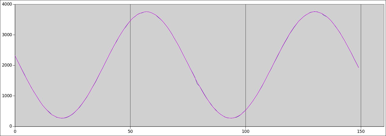
10 usec displacement
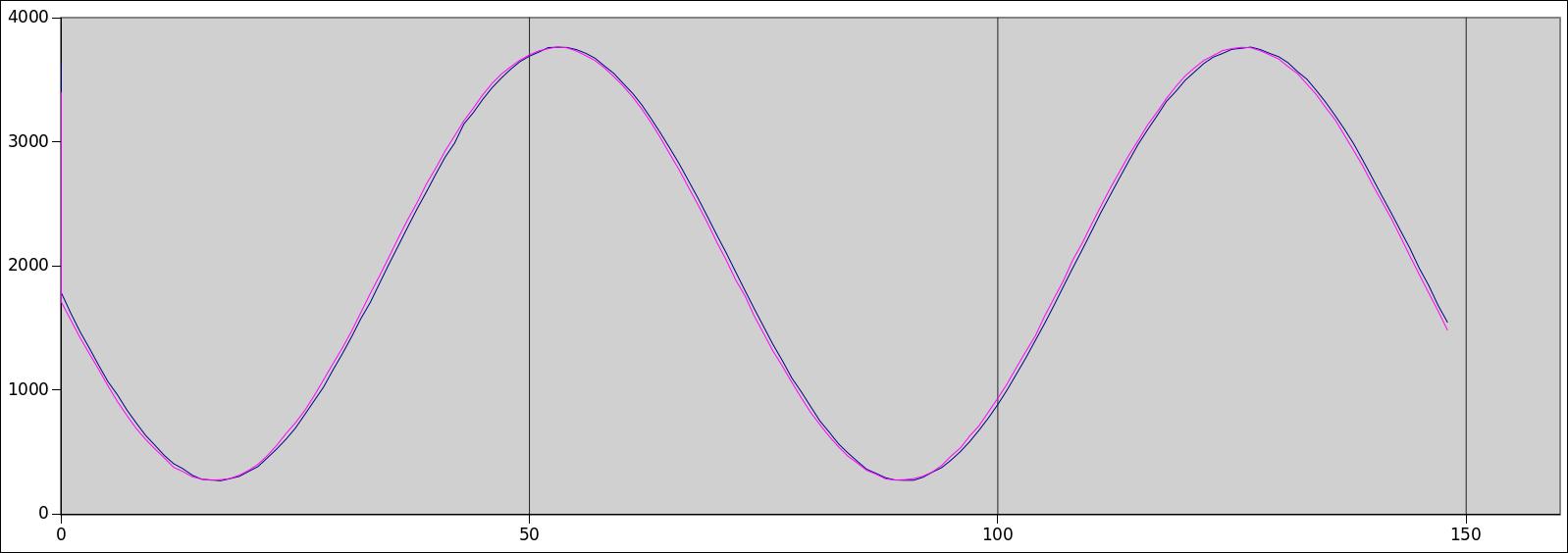
100 usec displacement
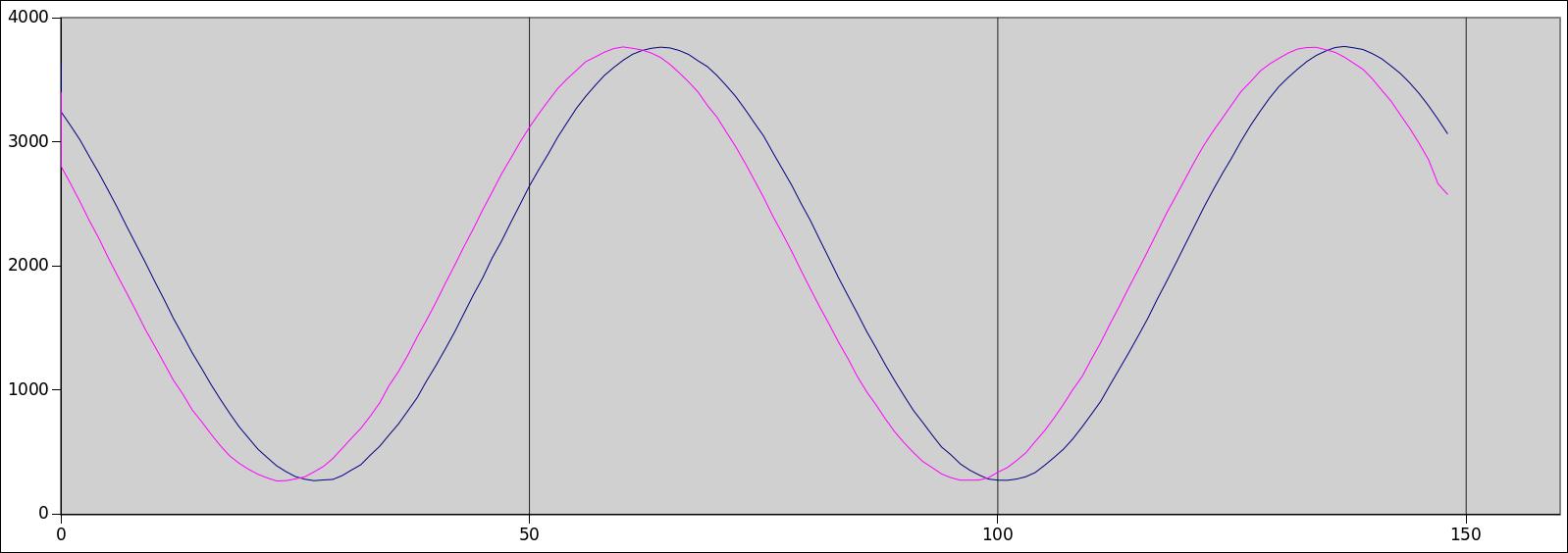
1 msec displacement
So we can do phase-shifts on the fly entirely in the analog domain down to 1usec resolution (~0.02 degrees at 50Hz). Actually, you could go lower but that seemed a bit over the top. And it’s programmable on the fly… -ish. You need to stop the ADCs, reconfig the timer, and then restart the ADCs, so it’s not something you want to be doing a lot of if you’re into continuous sampling, but certainly it could be a runtime configuration parameter, it’s not as if it needs to be baked into the image.
Credit to Robert for the suggestion, and credit to STM32MXCube for the code. I mostly hit “Generate Source”.