Solis S6 PV Inverter and RS485/MODBUS

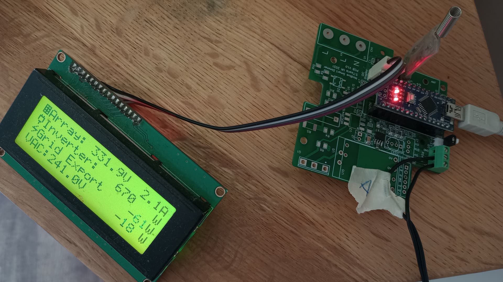
[specific model: S6-GR1P2K-M]

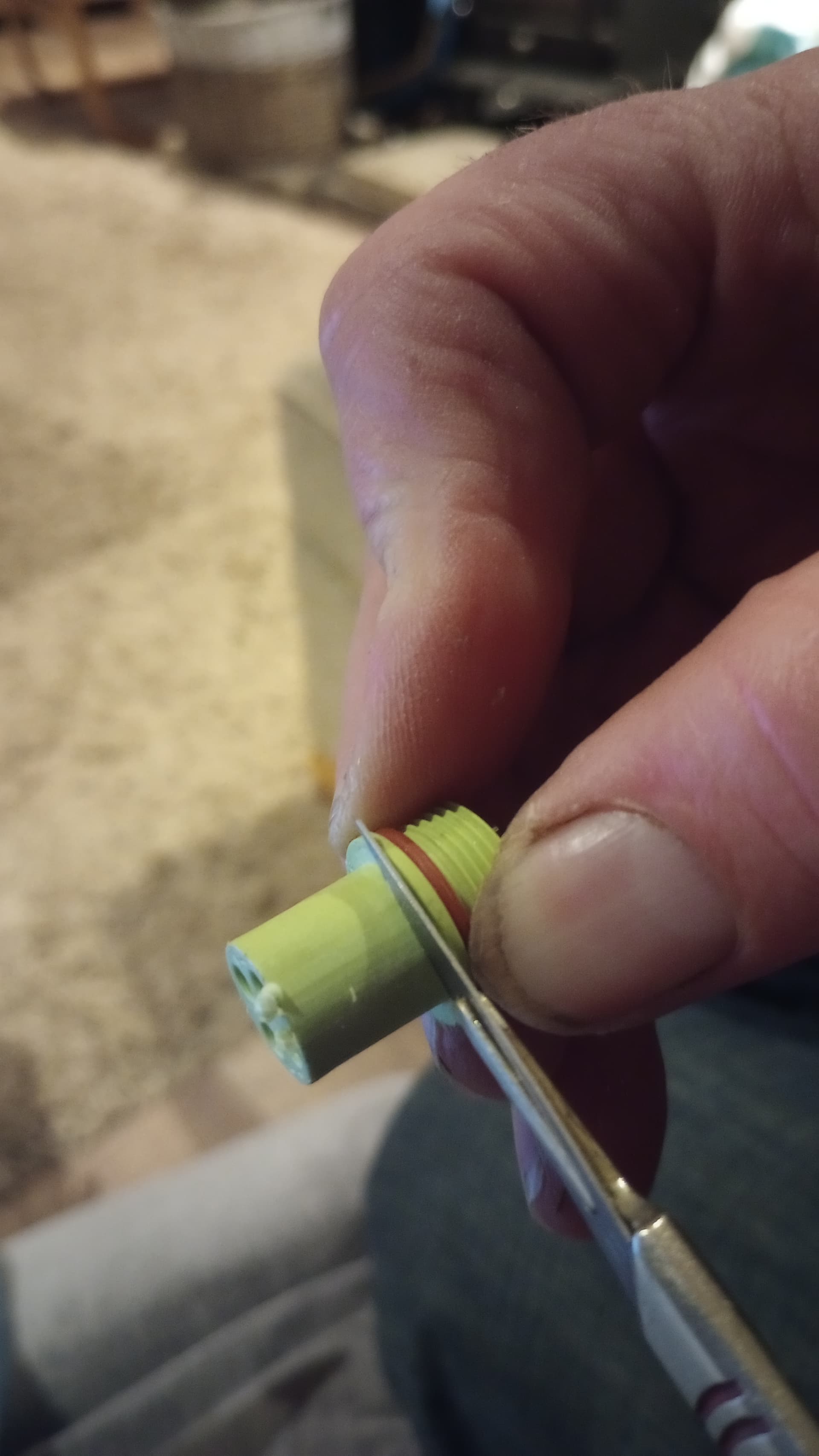
I’ve been attempting to extract data from the inverter using its RS485 interface, having purchased a “proper” plug. There seems to be an issue (at least one!) which I cannot find discussed so far, and I’m wondering whether the S6 has some quirk, or that I’m missing something.

Measuring the voltages on the “COM” connector of the inverter suggests that it is expecting signals with a +/- range of 3.3V; the A/B pins are about +/-1.6V with respect to the GND pin.

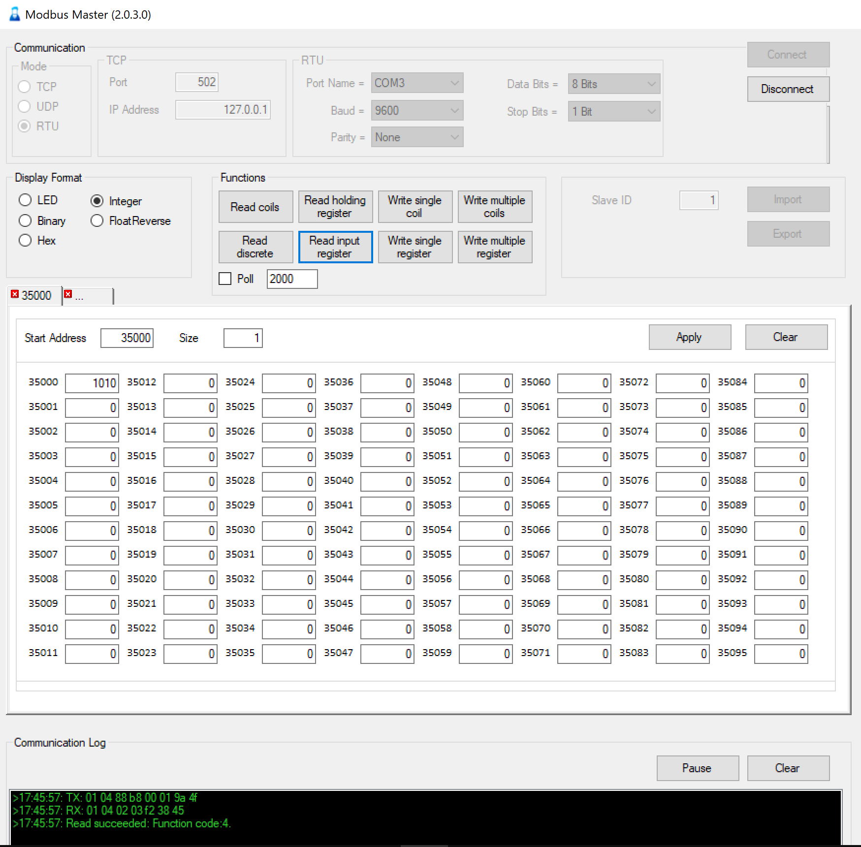
I’ve consulted the BA Coghlan document - from which I take it as a given that I should use 9600 baud 8N1 MODBUS RTU - and played around with transposing A and B.
I’m using Termite (with the Hex plugin) to send plain bytes, using an example from the Coghlan document (0x010480e8000c59fb).

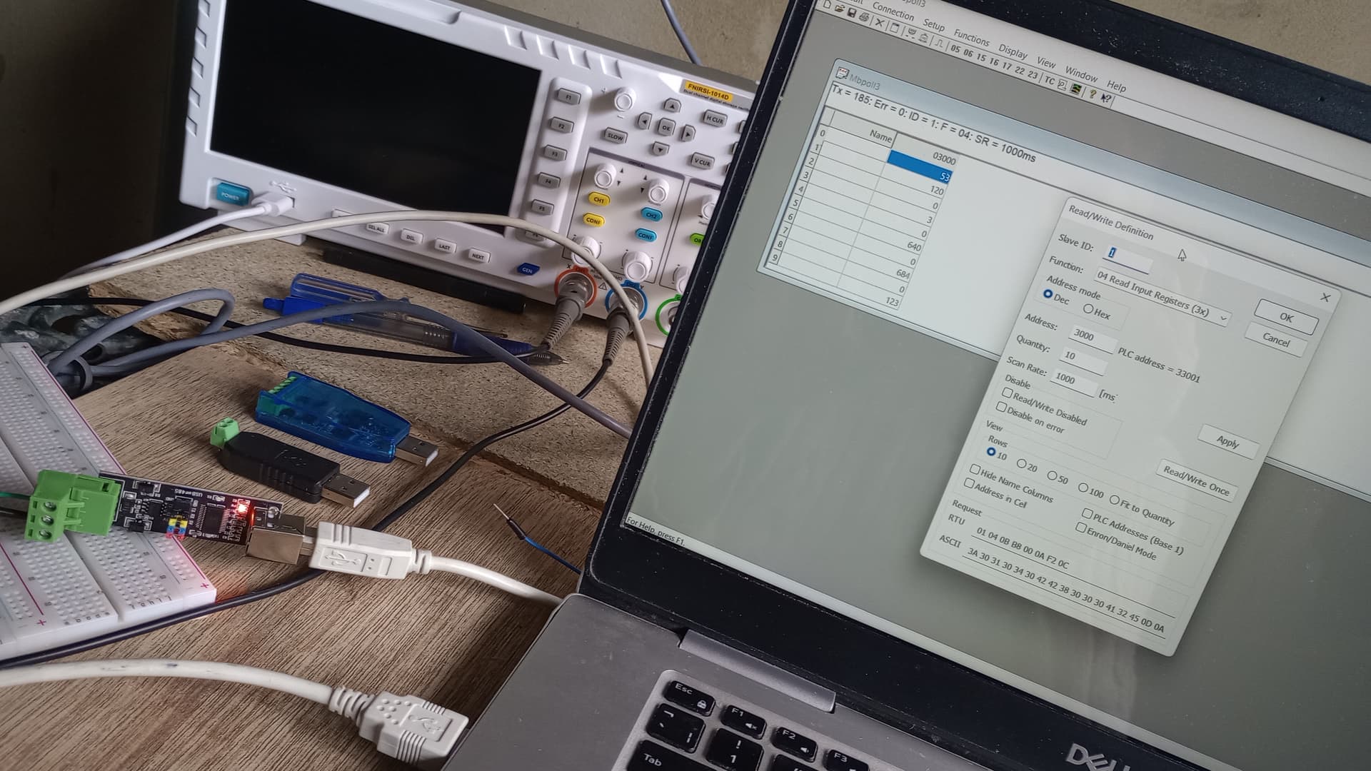
I have a cheap 2-wire USB device from which I can get nothing in response from the inverter. Connecting my Picoscope (PC USB oscilloscope) and using its MODBUS decoder, I CAN decode a valid MODBUS message, although I have to set Termite to use “mark” parity and the Picoscope decoder set to “none” parity (I suspect the decode may be at fault). The USB stick is: https://kunkune.co.uk/shop/communication-boards/usb-to-rs485-485-converter-adapter-linux-mac-os/

I have a FT232R USB-Serial board (previously used with ATMega 328 home-brew projects) and a TTL-RS485 adapter (Ttl Turn To Rs485 Module Hardware Automatic Flow Control Module Serial Uart Level Mutual Conversion Power Supply Module 3.3v 5v - Integrated Circuits - AliExpress, which appears to be hardware other people have had success with). The FT232 board has a 3.3V/5V jumper which controls the signal levels and the voltage supplied to the RS485 adapter. With 5V selected, I receive loads of gibberish without sending any message. I assume this is noise over the quiescent state +/-1.6V on the A/B pins. With 3.3V selected I can get a response, but it is not valid, as it does not start “0x0104” or “0x0184”. My hunch is there is a framing error, with something weird happening with a different parity, stop-bit length, or baud rate in the response. The response is always the same; this is NOT noise! Unfortunately, I’ve not been able to decode the response with my Picoscope because noise causes false triggers and its grounding is not independent.

Anyone got any clues???

Is it a hybrid inverter or just normal inverter you have

The doc you are chatting about is the hybrid one

The standard inverter has different registers
RS485_MODBUS Communication Protocol_Solis Inverters (1).pdf (592.3 KB)

I am using this to poll modbus data from the wifi logger
GitHub - jmccrohan/pysolarmanv5: A python module to interact with Solarman Data Logging Sticks that might help you.

I found the doc for the standard inverters on the us service site, I think it’s this doc…

Thanks for the doc, Graham; it is indeed a simple inverter.
It doesn’t solve my current problem, which I feel is a lower level protocol issue… but it will come in handy…

Hi Adam, Did you or anyone ever get 485 modbus working on an S6 ?

I seem to be having the same issue… Using the same cables, settings and RS485 dongle I can happily interrogate a Solis G4 mini… but with the S6 i just get timeout errors???

Cheers Steve

Steve -
no progress here (as I’ve been consumed by house renovation…)

Next on my list of things to try is capturing the response from the inverter to my raw RS485 messages using my picoscope and logic sniffer.
Also to contact Solis tech support. I did get a document out of them (UK) which is broadly the same as the BA Coglan one, so maybe there is more to be had, although I suspect the people who actually know are in China.

What we could really do with is for someone with a wifi dongle to capture the raw on-the-wire messages.

Adam

Hi Adam
After several hours messing around today I am sure there is something odd about the S6 compared to a G4 but i dont have a decent scope & no wifi dongle in this forum someone comments that wifi dongles maybe different across versions.

I am still looking around to see has anyone got a 485 connection successfully working on an S6.
My inverter, S6-GR1P3.6k-M, Software is Ver 780700003501 is new and was from ebay.

Still looking !

Have you seen Brian Dorey’s blog about Solis RS485 logging where he reverse engineered a Solis WiFi dongle and found “there are 10K ohm resistors fitted on the A & B data lines with the A channel having a 10K pull-up resistor to 3.3 volts and the B channel having a 10K pull-down resistor to ground.”

I don’t know if this is relevant to the S6 range but it may be.

Hi Adrian
Yes I had seen that, very interesting and I already left a comment to confirm the Solis inverter family being used.

I tried the suggested 10k pull up and down resistors with no luck. In desperation i purchased a brand new mk3 Wifi stick - this uses 4k7 resistors and a 1k terminating resistor across A-B I am seeing some pretty weird things going on - I managed to get responses today but only with the Pull up on A+ removed!.

My observations so far are mentioned in the attached document. It is looking like a very fussy, requirement for bias and terminating resistances or a hardware quirk / error. Maybe this is a fault on my inverter (its brand new), however, so far all I can find online are signs of RS485 coms difficulties on the Solis S6 series and no evidence of anyone successfully connecting to an S6. Connecting to my Solis 4G mini is 100% reliable and straightforward!

I would love to know - HAS ANYONE GOT A DIRECT RS485 MODBUS CONNECTION WORKING RELIABLY ON A SOLIS S6 SERIES INVERTER??

My notes and scope plots etc so far are attached.

Solis S6 Comms investigation - To be continued .pdf (1.9 MB)

Seems a bit odd as the RS-485 spec for terminator resistance is 120 to 150 Ohms
at both ends of the cable run.

The article says the terminators may be omitted for cable runs of less than 50 metres.

Ref:

Good writeup. My initial thoughts are around the dead time behaviour. The CA-IF4805 in your S6 has separate RE and DE pins (no doubt tied together) however some RS485 adaptors use bus drivers with built-in auto data direction logic e.g. MAX13487. Might there be a subtle timing difference if the enable logic is different due to the built-in state machine and you’re using one of these? I don’t know what driver chips you’ve tried but when piggy-backed, the dongle imposes it’s own authority on the bus.

Yes. I just got an S6 yesterday which is why I was trawling around for modbus info. Today I dug out a usb->serial adaptor and connected it to a MAX13487 board. This worked straight off the bat:

I think you might have a duff inverter because when I measure the open circuit voltages I get A+ wrt 0v = 3.3v and B- wrt 0v = 1.6V whereas you got 0.12V on B-

Incidentally, the RS485 pcb has 4k7 pull up/down and 100R series lke your Solis dongle but no terminating resistor by default. It has a link for 120R but I didn’t make it yet.

Thanks Adrian and All.
I spent most of the day looking into this - experimenting with various terminating and bias resistor values, made up a 3v3 FTDI / 485 interface and concluded its hopeless! - I can get replies if adjust bias resistor values / ratio but it seems critical and inverter response is intermittent. I am concluding there is something wrong with the input on this inverter, it seems that a slight shift in common mode voltage and the inverter may start or stop responding and the signal appears to get loaded. I will see Solis support ever come back with any ideas!. Thanks all.

My guess would be a solder bridge between B- and some other signal trace or component. No experience of the build quality from this manufacturer but it wouldn’t surprise me. Hope you get a satisfactory outcome.

PROBLEM SOLVED !!

OK All, I fear I may be winning Idiot of the week.

So, I had a working Arduino data acquisition system that has worked reliably for years talking to a Solis 4G mini and OB115 Power meter. I hung my new S6 on the wall, moved over the comms plug …Nothing! no response and many days wasted.

I had noticed the comms plug was a very tight fit into the new Solis S6 compared to the Solis 4G and it stopped 2.5-3mm from being fully in. I had looked at distance of male / female terminals from the faces and concluded ‘they must be easily mating’…wrong.

Adrians feedback reinforced my view something was seriously wrong so late last night I carefully opened the S6 up. The Comms connector wiring routes to the Display PCB, I continuity tested my cable / connector wires all the way to the PCB, Youv’e guessed it, B was not connected!!!
The connection break was occurring across (i.e inside) the socket-to plug interface despite the plug being pushed fully home as far, and as hard as physically possible, but, yes a small gap was visible near the o-ring. I still have trouble believing it was not making contact, but it most definitely wasn’t, the contact pin must have been sitting partly inside the receptacle without touching!

I drew thick pencil lines around the plug, inserted it, and could then see where it was ‘dragging’ and an interference fit. Irregular surfaces were visible on BOTH the plug and Socket (shrinkage / split lines?). These were easily scrapped away using a sharp scalpel, it now plugs in really easily!!! and this morning comms instantly worked.

At the start of this thread Adam mentioned ‘the A/B pins are about +/-1.6V with respect to the GND pin’. Possibly he meant when connected to the USB-485 adapter & scope. I would say before connecting any external devices, confirm the voltage on comms connector ‘A’ wrt 0V is approx 3.3V and ‘B’ is around 1.6V (my B measured around 0V).

This morning it instantly worked and connected to my Arduino device *(FYI This reads the Solis to conveniently / simply see what is being generated, plus it reads import/export power from an OB115 power meter. It transmits (via 433Mhz HC-12) the current import / export power value all around the home (5 times a sec or so?) to various sockets which then can either burst fire a Triac to proportionally ‘burn’ any export excess as heat in say our mini oven, kettle, electric radiator, immersion etc) or simply switch the socket On/Off (i.e for say a charger) depending on the level of export).

FOOTNOTE (Just to confirm Idiot of the week status and as a warning to others). This S6 was purchased from ebay identified as “Solis inverter S6 3.6kw dual MPPT” , brand new, boxed at a bargain price £300. I wanted it to support an East / West array setup.

So just look at the photos, i was really confused, x4 MC4 connectors on the base all simply paralleled at the DC isolator switch and then just two DC wires running to the PCB, this does not have two independent MPPT circuits !.

Look carefully at the Solis data sheet part numbers say S6-GR1P3.6K (which supports dual MPPT inputs) Or (mine) S6-GR1P3.6K-M (-M has one MPPT circuit but x2 PV inputs which must be connected to two PV strings of the same specs and orientation- it simply parallels them. This wasn’t clear to me and I never thought to check the part number.

Solis are nice inverters, internals look very well made, unfortunately I now need to get a Dual MPPT version !!!

Also:- the attached pictures show all USB-485 adapters used (ALL of these work fine:- the Blue one uses a fake Prolific PL2303 USB-UART and the driver install was a nightmare. The black one is CH340 based. The FTDI based ‘bare pcb’ one was looked at on a scope, the FTDI I.Cs and drivers accurately control the RS485 Tx and Rx switching so personally I favour these for speed etc maybe the CH340 one does too). There is also a pdf showing the Solis comms connector wiring which may be of use to someone.

Adam - If you still get problems drop me a message

Crap, What a week, i am off to the pub.

Solis RS485 Comms Connector Wiring.pdf (226.4 KB)


Glad to hear you found the problem. I’m currently coding a bridge to MQTT on an ESP32 for a generation data readout but I was initially challenged to find a plug that would fit (the German ebay listing that had theses has ended) although I felt sure I already had something like it somewhere… then I remembered, it was a vintage Garmin serial lead. The only problem being a pin pitch of 5.08mm not 5mm as on the Solis. I got it to fit by slightly enlarging the holes without disturbing the contacts.

beer_cheer thumbsup

Thanks for all the updates.
I’m sure there are plenty of highly qualified and very experienced engineers who’ve been bamboozled by a dodgey connection.

It is certainly VERY GOOD to have reports that this can work (there are so many sources of uncertainty otherwise), and I heartily approve of putting this stuff “on record”.

I’ll have a poke at my connector. It could well be the culprit, as I recall it being quite stiff. I also saw a lot of noise on the oscilloscope trace (I put this down to inverters being bad for EMI, but maybe a poor contact is really the fault).

Cheers, Adam

1 Like

Another good rule is to be ready to believe that something that can’t possibly be the problem really is the problem (which is much the same thing).

Bear with on this one. I had the same problem and didn’y have anything similar do ordered a quantity of Excedconn ones from China. I will list the ones I don’t need on eBay.

Glad you solved your problem. A two questions if you don’t mind?
I think I bought the same S6 from eBay as you did. I got it to install with my single string panels whilst waiting for GivEnergy G2 kit to be delivered. I haven’t got a Solis CT, it’s just running free out-of-the-box. For my own info I have an Arduino-MQTT CT monitoring the output.

  1. I have an OB115 Power Meter ready to install with my GE kit. Have you interfaced yours to your S6, or did I misunderstand? If so how?
  2. I’m planning on building an Arduino-MQTT Solis interface just a soon as the Exceedconn plug arrives form China(!). As plagiary is the greatest form of invention - Did you share the code for your Arduino project anywhere?