If you bought your S6 from the same seller I really hope you didn’t require the dual MPPT version!
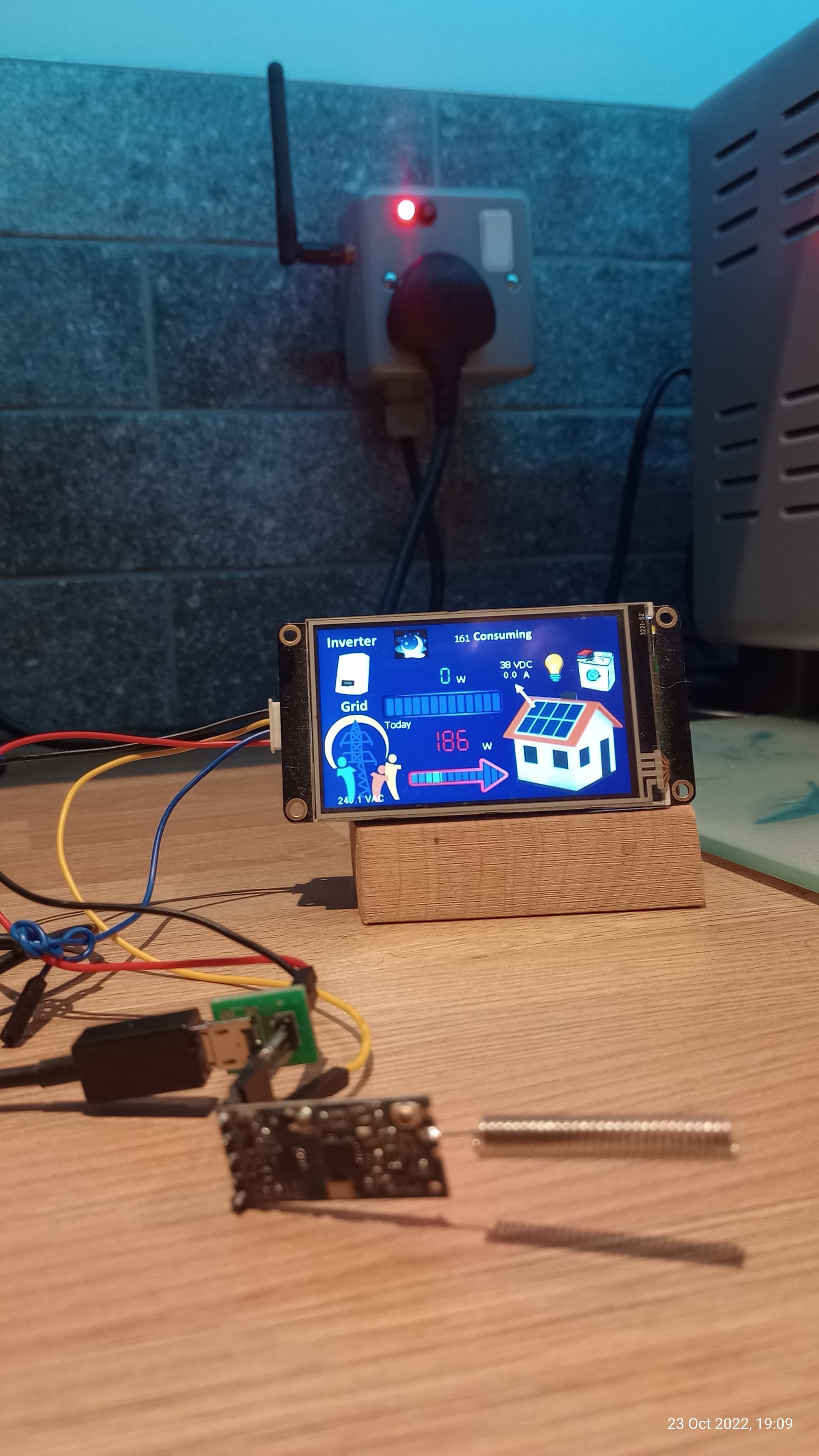
Ah No… I have an Arduino acting as Modbus master reading both the Solis (on Address 01) and the OB115 on address 02. The Solis has no method to access values from the OB115. The Arduino board receives the Modbus, then transmits values via 433mHz in Nextion display format. Data can go straight into a remote Nextion display and also to ‘smart’ sockets which intelligently switch connected loads on /off or proportionally ‘burn’ whatever excess (export) power is available. The socket in photo adjusts power delivered to a small oven such that on a cloudy day etc we can avoid any grid import.
I have some projects on Arduino Project hub (for PV Hotwater) but not this Modbus / Smart socket yet, maybe that will be a winter project if there is any interest.
I’ve attached a zip of the code for the master end (the PCB shown in the earlier post above connected to a 20x4 LCD).
Your system looks really interesting. I’m a Home Assistant user, mainly because I have half a dozen different pieces of kit and other people have written the interfaces for them. Also I don’t have the skills to do anything too complicated. But if I have something similar to work from I can get there so thanks for your code.
I’ll probably stick with my existing Nano33 + CT measuring the S6 output Power and use another Nano33 + RS485 to work the modbus based on what I can learn from your project. If I find out that the S6 can’t give meaningful data without a meter input, I’ll have to see if that is a writeable data and if so I may try to get the OB115 part implemented.
Cheers
Thanks to this post I’ve made some progress…not with a direct RS485 connection to the inverter, but via a TCP-based MODBUS connection using the Solarman integration in home assistant. It is a bit of a pain to get the wifi stick configured on the inverter but if you manage to fluke it then you can get access. What I was completely stuck on where the MODBUS addresses to get to registers I need to read…thanks to the posts here and some of the links provided I’ve been able to scrape together quite a bit of data. However, none of the addresses that actually work are the same as those posted in the Solis documentation…can anyone point me to a MODBUS map for a S6 inverter? I’m thinking there must be one somewhere…it’s hard to guess your way to the right registers…
Try asking the Solis support people (there is a UK email address). I got a document without problem.
There are a couple of reasons why addresses can be troublesome (you may already know these):
a convention to add a leading digit e.g. 33072 vs 3072. I’ve seen this done inconsistently within 1 document. The address to send to query an input register would be 3072.
the presence of an “offset” applied to the address sent to determine the actual register to read. For example, on my Solis S6, the active power is documented as being in the register pair 3005-6, but there is an offset of 1, so the address to send is 3004.
FWIW, here is a snippet from a short Python program I used when experimenting:
print("Active power = {}W".format(solis.read_long(3004, INPUT_REGISTERS)))
print("Total DC output power = {}W".format(solis.read_long(3006, INPUT_REGISTERS)))
print("Total energy = {}kWh".format(solis.read_long(3008, INPUT_REGISTERS)))
print("Total energy (this month) = {}kWh".format(solis.read_long(3010, INPUT_REGISTERS)))
print("Total energy (today)= {}kWh".format(solis.read_register(3014, 1, INPUT_REGISTERS)))  # unit = 0.1kWh
print("Inverter temp = {}C".format(solis.read_register(3041, 1, INPUT_REGISTERS)))  # unit = 0.1C
print("Grid freq = {}Hz".format(solis.read_register(3042, 2, INPUT_REGISTERS)))  # unit = 0.01Hz
And the log of the actual byte sequences sent and received:
Will write to instrument (expecting 9 bytes back): 01 04 0B BC 00 02 B2 0B (8 bytes)
Response from instrument: 01 04 04 00 00 00 32 7A 51 (9 bytes)
Active power = 50W

Will write to instrument (expecting 9 bytes back): 01 04 0B BE 00 02 13 CB (8 bytes)
Response from instrument: 01 04 04 00 00 00 77 BB A2 (9 bytes)
Total DC output power = 119W

Will write to instrument (expecting 9 bytes back): 01 04 0B C0 00 02 73 D3 (8 bytes)
Response from instrument: 01 04 04 00 00 04 1C F8 8D (9 bytes)
Total energy = 1052kWh

Will write to instrument (expecting 9 bytes back): 01 04 0B C2 00 02 D2 13 (8 bytes)
Response from instrument: 01 04 04 00 00 00 64 FA 6F (9 bytes)
Total energy (this month) = 100kWh

Will write to instrument (expecting 7 bytes back): 01 04 0B C6 00 01 D3 D3 (8 bytes)
Response from instrument: 01 04 02 00 2C B8 ED (7 bytes)
Total energy (today)= 4.4kWh

Will write to instrument (expecting 7 bytes back): 01 04 0B E1 00 01 63 D8 (8 bytes)
Response from instrument: 01 04 02 00 C2 38 A1 (7 bytes)
Inverter temp = 19.4C

Will write to instrument (expecting 7 bytes back): 01 04 0B E2 00 01 93 D8 (8 bytes)
Response from instrument: 01 04 02 13 8A 35 A7 (7 bytes)
Grid freq = 50.02Hz

Will write to instrument (expecting 7 bytes back): 01 04 0B E3 00 01 C2 18 (8 bytes)
Response from instrument: 01 04 02 00 03 F9 31 (7 bytes)
Status flags = 0x3
I’ve managed to make some progress…ditching the leading ‘3’ helped, as did figuring out that you needed to use an address lower than the target to start the read. I’m a little limited in that I have to fit into the Solarman integration, but so far I’m pulling the following:
DC Current x2
DC Voltage x2
DC Power
Working Mode
Inverter Status
AC Voltage
AC Frequency
AC Active Power
Inverter Temperature
Generation Stats (today, Month, year, total)
For the working more and status I’ve found some syntax for converter the data to a text-based status and that is working well. However I’m still stuck on these:
Apparent Power (crazy high numbers)
Reactive Power (crazy high numbers)
AC Current (always seems to be ~3x higher than expected based on Active Power / Volts)
Operating Status (need to figure out how to decode bits as each bit is an on/off for a specific state).
I didn’t look at things like reactive power, suspecting that interpretation requires rather more understanding of what the inverter is doing than the doc tells.
The offset might just be the difference between the register number and the register address. The numbers will start at 1, but the addresses will start at 0. Quite common on MODBUS systems.
That number/address offset thing took me a few minutes to work out but I suppose it’s exactly the same as the first bit of data in an array being at address zero.
I got my Solis S6 interface up and running if any of this helps here:
Exactly and I have been caught by it too often. I should learn really, but it is so easy to read the register number on the docs and put that in the code/config