We’ve just had a Solar PV setup installed along with 2x 3.5Kw batteries. I’ve reviewed the guide here: Solar PV - Guide | OpenEnergyMonitor regarding the setup of the emonpi with solar PV but I’m not entirely sure how I would go about integrating monitoring for the batteries.
For those that have this setup, is there a resource you found useful? I’m unsure where to begin with this.
Is this a hybrid inverter? With the batteries on the DC side (ie, the solar side?)
Or do you have a separate inverter for the batteries. Ie, on the AC side (the mains side).
I have a separate AC inverter and monitoring the ins/outs of the batteries is as easy as putting a CT clamp on the AC cabling to the battery inverter.
If you have batteries that are on a hybrid inverter and stay on the DC side I think it’s gonna be tricky to monitor with CT clamps as they look at the AC side. If that makes sense?
What model solar/inverters/batteries have you got?
The other place to start looking is, what information can your inverter provide, and how? i.e. is it possible to extract the data via a data port (e.g. Modbus, MBus, etc)?
If the battery is connected directly to the inverter/charger, this might be the only way of knowing what’s happening to the batteries themselves.
As my namesake suggests, if the solar inverter and battery inverter/charger are separate, it’s dead easy with c.t’s. The trouble is, no transformer can ever work on d.c. (Anybody who says otherwise doesn’t know what they’re talking about.)
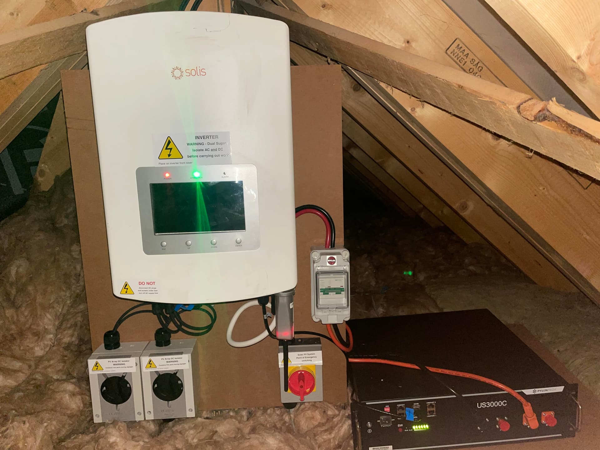
Thank you for your replies. The inverter that’s been installed is the Solis Hybrid 3.6Kw 4G Dual MPPT
We have an iphone app that shows generation/battery storage so it’s entirely possible I might be able to scrape that data. I own an EmonPi and was intending on setting it up for PV type2 monitoring but that left the battery storage out of the equation.
The emon documentation for the type 2 setup is excellent but after some searching around the site/forum/google I was still unsure of where to affix a clamp or how to configure that data in emoncms. This is somewhat of a research project at the moment as I’m at capacity with 2 CT clamps on my Emonpi and currently waiting for for the EmonTX to be back in stock before I can expand.
If you do that, without any further input from the inverter, what you’ll have is display and a record of the nett grid power/energy and the nett ‘alternative’ power/energy from the combination of battery & PV.
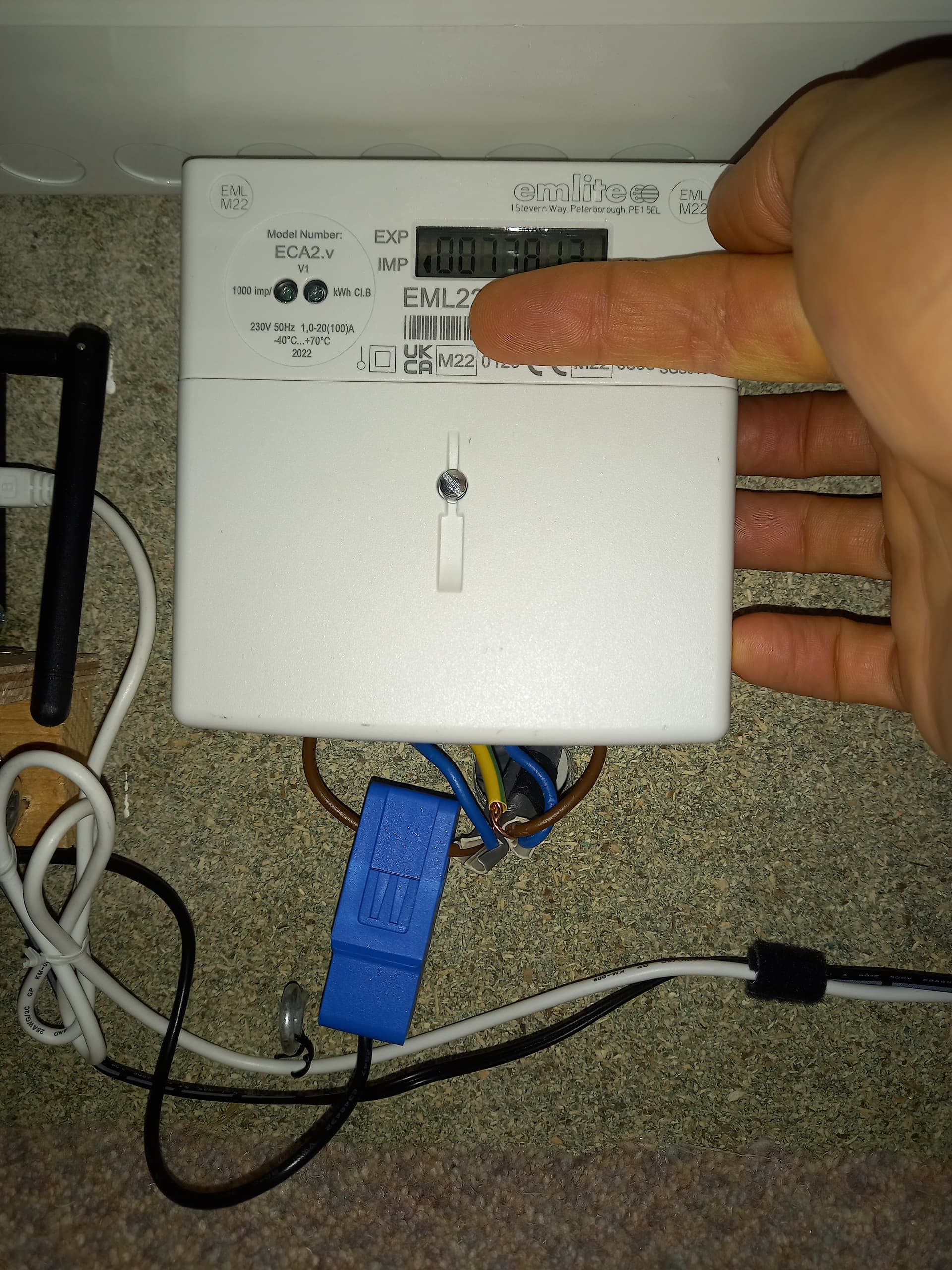
CT1 (please don’t call them clamps - those are things I use when sticking two pieces of wood together) goes on a meter tail somewhere upstream of your consumer unit; CT2 will need to go on a single core of the PV infeed where it joins your house wiring, which could be tricky and I’ve no idea where that is in your house.
The Inverter datasheet says: “Communication: RS485, Optional: Wi-Fi, GPRS” (I think that means RS485 is standard, which we can handle.)
However, there’s nothing in the manual that’s helpful. What you need to know is where are the RS485 bus connections, what is the protocol and data (baud) rate they use, and most importantly, what are the register numbers for the data.
You’re going to need cable and a RS485 - USB adapter, and with the correct emonHub driver, it looks as if you will get data. It won’t be that easy of course, but I think there’s a realistic chance you’ll get it working, with some help from people here who know more about this aspect.
When you have the battery data, you’ll be able to integrate it with the data from the c.t’s using the Input processes in emonCMS and hopefully get meaningful information.
I really appreciate you taking the time out to explain and you’ve given me a jumping off point. I’m reasonably computer savvy so interfacing via RS485 doesn’t sounds too scary. I’m less knowledgeable when it comes to power, as you can see by the use of the term “clamps” thanks for correcting me. You gotta start somewhere right?
Indeed – and be warned, it’s a steep learning curve. However, we’ve all been there once upon a time, and it does get a little easier as you get familiar with (particularly) the thinking behind everything.
If you find out how and where your PV feeds in, probably by identifying the cables, then I’ll be able to make a suggestion as to how to mount that c.t. It’s more than likely it will be a 3-core (L,N,E) cable but (1st power lesson ) a c.t works on the magnetic field around a single core cable. When you have a 2-core or a 3-core with 2 cores carrying the same current but in opposite directions, the magnetic fields cancel each other and the c.t. reads nothing. That is until you unbalance the currents with a fault to earth, then you have a RCD or RCCB (Residual Current Device or Residual Current Circuit Breaker, otherwise known a earth leakage detector).
This is how I clamp the CT2 onto the PV feed (Type 2). My installer left just enough slack in the twin and earth that comes from the inverter in the loft below the generation meter…
Other ideas - if you have an iPhone App it’s probably connecting to some cloud service rather than directly to the inverter, can you get it from this? I know Huawai invertes connect to a cloud and there is a JSON API you can call to get data, although it only has a 5 min refresh rate, I stopped investigating this and went with the CT2 route instead.
You can measure DC currents with hall effect Arduino modules like this one but it’s messy I suspect your batteries plug directly into the inverter so you would need to cut the cables, it’s also limited to 10A which might not be enough depending on peak load? https://media.digikey.com/pdf/Data%20Sheets/Watterott%20PDFs/201876-002_Web.pdf
And that in fact is illegal. The single cores have no protection against mechanical damage. I assume you don’t know that the wire’s insulation is relatively soft PVC, the (normally grey) outer sheath, which some refer to as insulation but isn’t insulation at all, is much harder and stronger and is there to afford mechanical protection.
To anyone reading this, DON’T DO AS CARL ADVOCATES, IT IS NOT SAFE.
I advocate nothing… I’m simply showing where I placed the CT on the system installed by a MCS and SELECT certified PV installer.
Practically though I don’t see a problem - It’s 6242Y 2.5mm Prysman cable, there’s strain relief (you can’t see in photo) The CT does not move it’s all in a box so not subject to the risk of a knock. I looked at the cable spec and an off cut I have this morning, both phase insulation and the sheath are PVC, there was no feasible way insulation it’s going to get damaged.
I am curious now, what have you and other PV with emonpi’s owners done for CT2 placement? Given CT has to go round the phase conductor for the inverter to the consumer unit connection and it’s normally run with Twin & Earth?
In my case - I had three choices:
The inverter end, the T&E vanishes into an isolator box, don’t fancy opening it and it’s not got space for the CT anyway.
Consumer unit end I would need to open the consumer unit to see the phase conductor, place the CT in a tight spot between other cables / MCB’s and then get the CT signal cable out the back running along with all the other T&E cables to where the PI is. I remember from Ethernet in trunking days you are not supposed to run Band1/ELV (i.e. the signal) cable and Band2/LV (i.e. the mains) in the same conduit, although this was a decade ago.
The connections to the generation meter - where you see it
I see the install guide has a photo and tells you what NOT to do (clip round the T&E sheath) but does not reccomend anything…
In all honesty, it looks as if that work was done down to a price, not up to a standard.
in my (old) copy of “The IEE Regs”, it says “Good workmanship and proper materials shall be used.” It looks a bit lacking in those respects (viz. the generation meter is not designed to accept T&E cables, so either the meter or the cable is wrong). I do hope there’s suitable protection upstream of the 2.5 mm² cable, and it’s not relying on the supply fuse for protection. @carl_afgte45 infers it’s downstream of the C.U, if so it’s most likely OK.
I’ve seen work by trade registered firms and individuals that shows scant regard for the regulations, so I remain sceptical.
Here’s a quick snap of my inverter/battery install. At first glance the cables to/from the battery looked like an obvious place to attach a CT but then I remembered someone mentioning that you cant use a CT to measure DC and I’m guessing that’s what’s going to and from the battery.
Can anyone suggest a good place to take a measurement from this photo?
That was most likely me. No transformer works on d.c. You need a changing magnetic field to induce a current in a stationary winding. D.C. won’t give you that changing magnetic field.
If the magnetic field is not changing, either it or the winding needs to move. Something that does that is called a generator.
What is on the bottom of the red isolator? I would expect to see two cables - the output from the inverter/charger, and a cable to the grid via (presumably as it is in a loft) the consumer unit. The c.t. needs to be on a single core of that cable.
What I suspect you might have to do is isolate everything - the PV/battery infeed at the C.U., the battery and the inverter, take the link cable from the C.U. out of the isolator and into a separate box which will house your c.t., then use another same-size cable from the c.t. box into the isolator. Both cables will need to enter the c.t. box via suitable glands, and the box will need to have a screw connector block and a loop of either the line conductor or the neutral on which the c.t. sits. You could have more than 1 turn through the c.t. if you need more sensitivity.
What is the switch on the right, just above the big red isolater switch, with thick red and black cables going in and out and round the back. Looks like it some form of RCD/surge protection and isolater? A check on the wiring diagram and start up/shutdown instructions which your installer should have left fitted somewhere nearby should provide some guidance. If it is in the AC output feed from the inverter then simply clam CT2 around the red wire.
Reading this with interest since I have a SOLIS inverter (a but older than yours) but with a Tesla Powerwall 2 installed on the AC side and am trying to get my head round where to place the current sensors to measure the (real) grid input/export, the Powerwall import and export, the house usage and the air source heat pump load!
Following more research Zarch was exactly right - I have a hybrid inverter and all the input/output cables with the exception of a connection to the grid are DC. This means at very best I’ll be able to monitor energy that originated as solar. However won’t be able to split out battery charge/discharge and direct usage.
In contact with Solis to see if they can give me access to their API to get the data correctly. There’s some reports of people online who have been successful. Others not so much. Wish me luck!
There appears to be an integration with home assistant,using modbus for some solis inverters:
so perhaps it’s not that hard to connect the inverter using modbus and use emonhub to read out the correct values. I wrote the goodwe integration for emonhub based on the home assistant python code (integrated it as module), so I believe there are plenty example codes available to get you started (if you know your python offcourse)