I have a spare PCB for a controller, Picked it up on ebay cheap
However on the board it says 2023.05.05
Would you only recommend upgrade via MIM-C02N or did you make a mistake doing the snet option?
I have a spare PCB for a controller, Picked it up on ebay cheap
However on the board it says 2023.05.05
Would you only recommend upgrade via MIM-C02N or did you make a mistake doing the snet option?
Hello again @mrsimonbennett.
Based on my recent painful experience, do not try to update the Micom using SNET (when I tried, I got the dreaded “CRC error” before the thing locked up irretrievably). In fact I’m not convinced that the “new” FSVs (e.g. #1061) are available without installing a Rev 01 PCB (see above). I rather suspect that a 2023.05.05 PCB is likely to be a Rev 00, in which case I’d be doubtful that it can provide for the new FSVs whatever you do (I’m not even sure that the MIM-C02N can do anything in this regard). Maybe call Helpdesk to get their perspective?
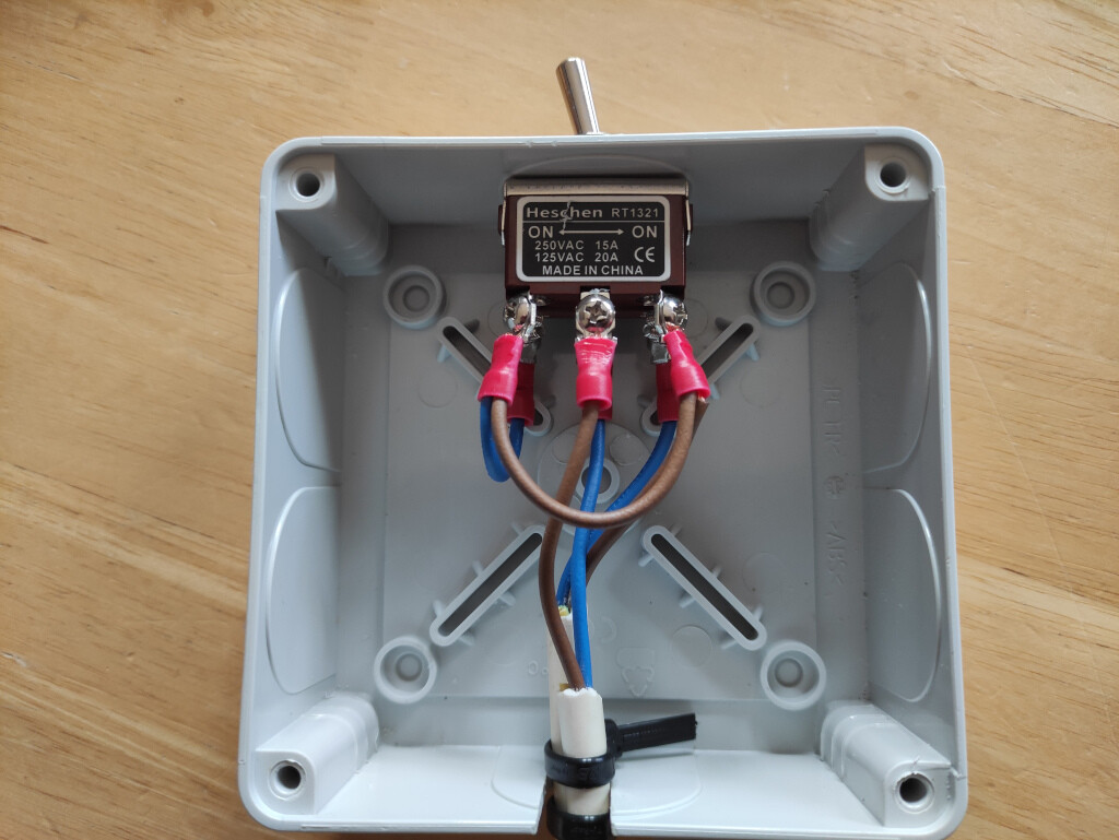
Back on topic, I decided to go with a manual switch rather than the automated solution @Michal_S has implemented. Referring to the Samsung manual:
I needed to ensure than B17/B18 were OFF/ON for heating and ON/OFF for DHW operation.
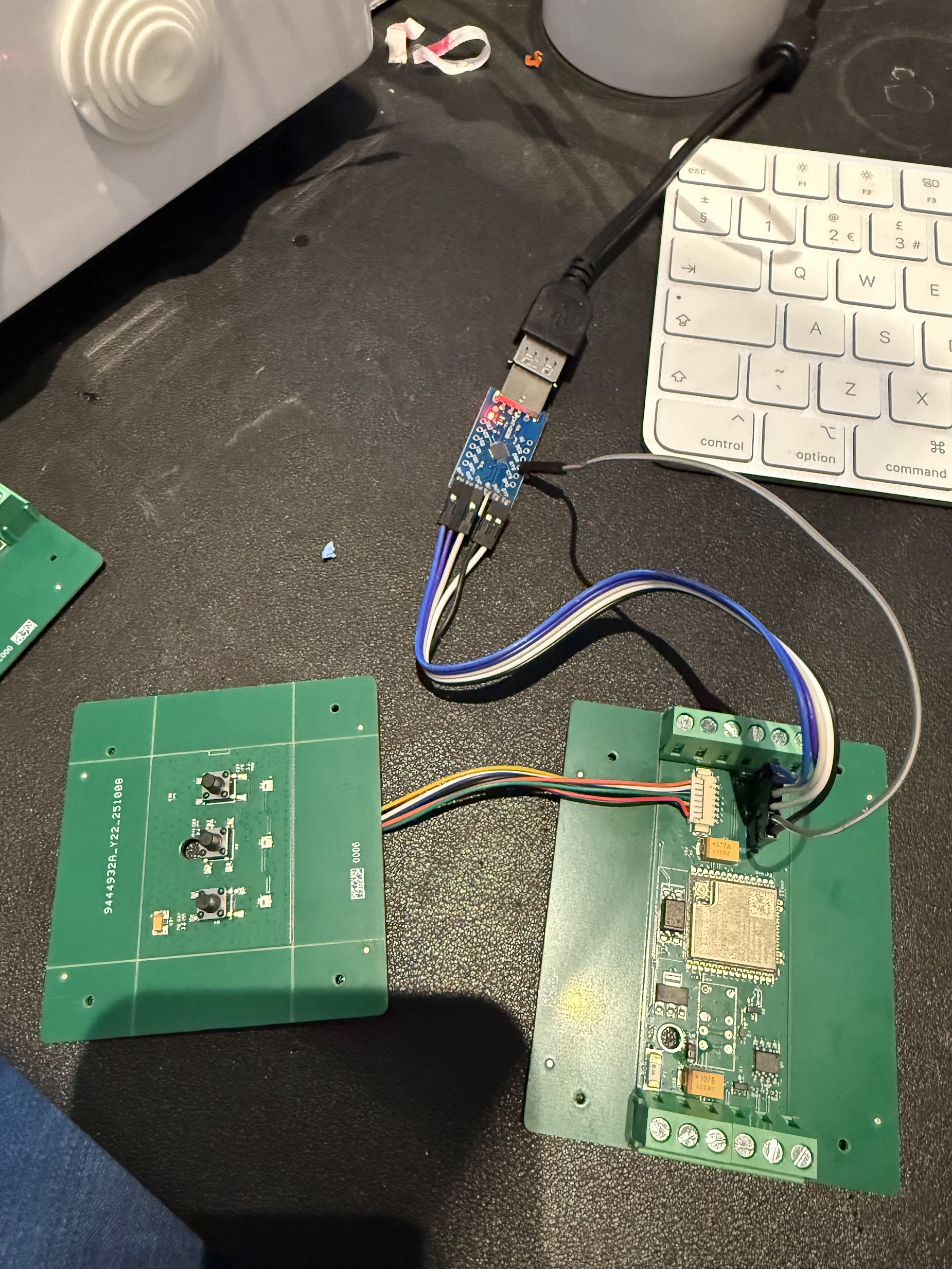
To protect against AF/AS cycles, I needed to ensure B18 was always powered (from either B17 or B18), but that B17 at the valve was not, so implemented this via a DPDT switch. I cut into the B17 and B18 wires linking the Samsung controller to the Joule circuit board that controls the valves, and connected to my DPDT switch:
I’m still in the process of testing, but so far so good. Under normal operation, space heating and DHW work as normal (as expected).
In Test mode, with the switch in the normal position I can hear the relay activate and the DHW valve move when turned on and off. If I move the switch to the ‘protected’ space heating only position, and again try to activate the DHW valve, I hear the relay click but as expected the valve doesn’t move (or at least I cannot heat it move). Result.
I now await some colder weather to fully test, but I’m confident I have a working solution. We will just flick the switch whenever we are expecting colder weather overnight.
My thanks to @Michal_S for sharing their relay solution.
Edit: I used Wago wire connectors that are excellent quality and really easy to use making the connections very simple.
Reviewing my original post:
An alternative solution would have been to switch in a fixed 20K resistor in the outdoor unit so the thermistor could be switched back and forth with a 20K resistor for a constant 7C overnight. The main reason I decided to implement a switched solution for the 3-way valve was not having to fit a switch to the outdoor unit (i.e, waterproof), although the wiring would probably have been easier / more accessible.
I was actually really silly on this, I do have 1061. So going to give that a go (not that it did anything the first attempt and changing it from 0). Both my PCBs are 2023.05.05. But I guess it must have had newer firmware.
Well, I don’t know TBH, maybe it has no negative impact but my OCD tells me it’s simply not right to see these teeth on a chart. Another negative aspect is that long lasting zig-zag pattern decreases efficiency pretty much. Easily by 1COP point.
Is the old one without the new FSVs ? Maybe you could try to flash it to see if you will have new options. Then I could try it as well maybe but Sarah said something it will probably not work after flash anyway. But to me it looks strange because it’s simply a firmware to control the pump, why new revision board should be required ? I made a post on a Facebook with request if someone from Slovakia is able to update the firmware for this unit and guess what - no one replies. Unbelievable. It looks like I’m the only one who has this crap in Slovakia :))
You are welcome but can you describe how you want to use this manually? Sounds odd to me. What is exactly the use case ? I’m asking because from my experience below 5C the pump is doing AF cycle every hour or so if space heating is not running. This could be fine in case your pump is running 24/7 when below 5C. In summer you can’t prevent AS in case you don’t use DHW for more than 24h. You want to stay next to the switch or how exactly you want it to operate ?
Now I read this. So both your boards have 1061 ? Would you mind to sell one for some good community price ? ![]() Can you tell me where I can see this number ? Possibly without opening the controller
Can you tell me where I can see this number ? Possibly without opening the controller ![]()
The switch has two positions - one allows the system to operate normally and the other effectively locks the 3-way valve in the heating position by ensuring B18 is always powered and B17 is off.
I know when I’m likely to be affected by either AF or AS cycles, so can now manually ‘switch’ to protect against these, by locking the 3-way valve in the heating position.
In winter, AF occurs mostly overnight when we either turn the heating off or the heating cycles off due to set back on the room thermostat for more than one hour, and the OAT drops below 5C. In the ‘locked’ position, heating is unaffected and can continue to operate normally, but we would need to switch back to the normal operation position to allow the 3-way valve to open for reheating of the DHW tank.
In summer AS occurs when we do not regularly reheat the DHW at the same time every day, or do not reheat on one day and more than 24h passes.
We normally reheat our DHW daily (most days), so as long as the switch is switched back to allow the 3-way valve to operate normally before we turn on the DHW, this works fine for us.
So for us everything is done manually. We do not have any automation and do not try to detect and then prevent or mitigate AF/AS cycles, but rather use the switch to ‘lock’ the 3-way valve in the heating position if we know or think an AF/AS cycle is likely.
We have a 50L buffer tank on the primary return which will always contain warm water and will certainly be sufficient to prevent any freezing without taking heat from the DHW tank, and in summer for anti-seizure it makes no difference where the water comes from as long as the pumps regularly run.
Hi Simon,
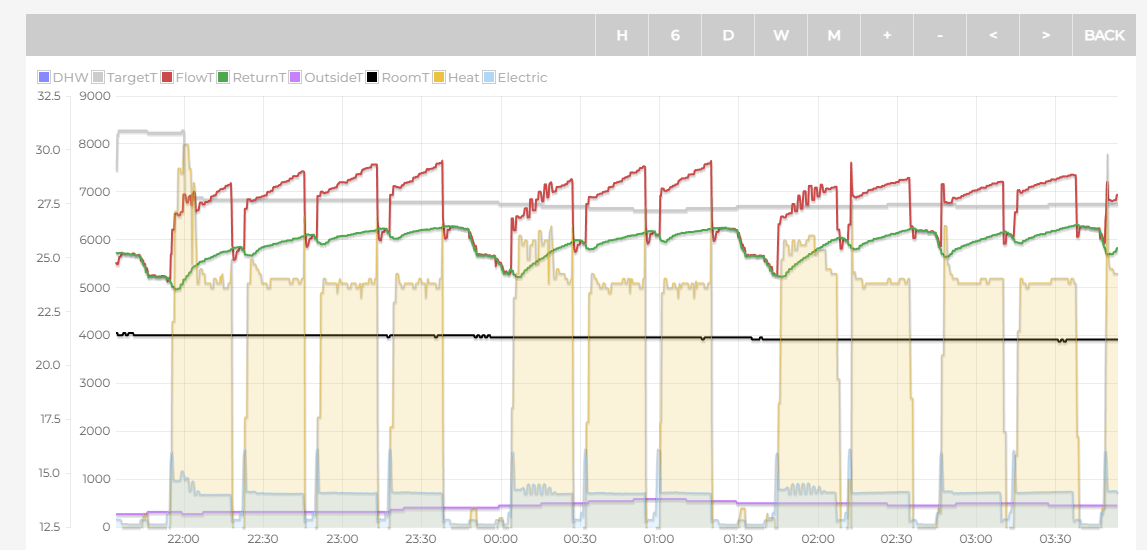
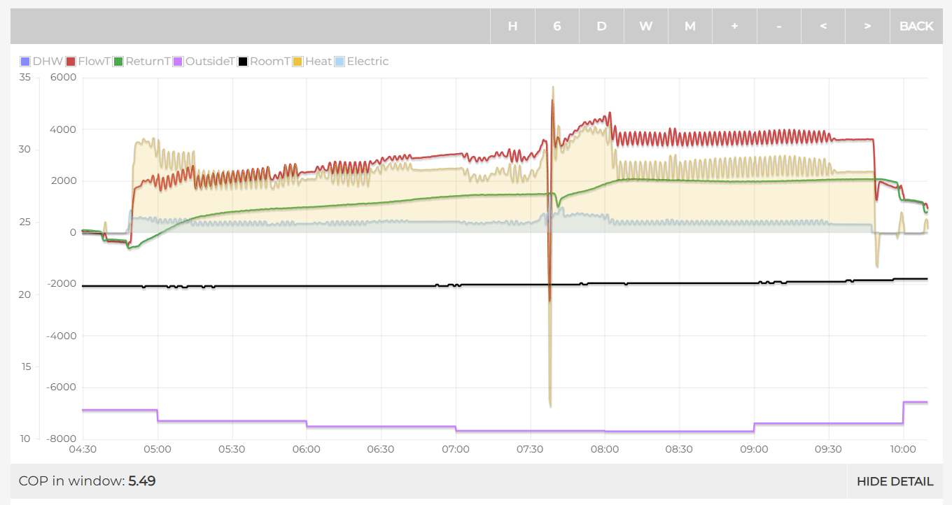
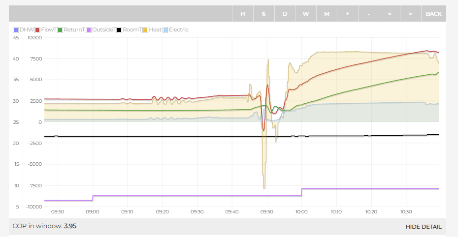
Looks like you had a couple of instances of #1061 working last night but I think you need to increase the value a little. Looks like you have it set at around 2 but most of the time LWT is immediately dropping more than 2 degrees below target so cycles on again. For reference, I have mine set to 3.5 and over the same time period, I have fewer and longer cycles.
Can I ask how you’re changing the target water temp? Presumably you have WL on, are you making changes to the target temp by the -5 to +5 adjustment setting on the home screen?
Yours
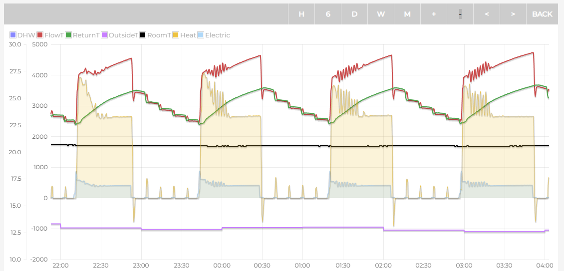
Mine
I don’t know what version of software my second PCB has. I got it to experiment with a smaller unit, as sometimes they come up on eBay. I will look at the paper manual to see if 6010 is there. Might be willing to do a swap.
So yeah, last night I had it set to 3. Just bumped it to 3.5. I didn’t realise that setting existed as I was using MidSummers users manual, and It didn’t have the option.
I have a much bigger unit than you, and I think it’s 40% oversized, so with this milder weather, I won’t have long runs until 10 °C outside. I am trying to extend it, as I could defo cope with longer runs with longer breaks.
I don’t have water law on, I am using Modbus to send a target temp to the unit. I was trying to read in the manual about the 1061, and I can see it only sets the water back on temp, not off, which seems to be locked at 2 °C. I was trying to work out how that off-process works.
Like if its the out temp is over target temp by 2c for 1m, could I pump the target out temp up by 2c just to get the unit to keep running without it responding with increasing the compressor Freq.?
Mine is nearly 100% oversized, so I feel your pain. I could get away with a 5kW unit comfortably.
I think if you can dial in your #1061 setting you wont need to worry about increasing the target temp to avoid cycling. The higher your #1061 setting, the lower your LWT will drop and therefore increase cycle times naturally. I also find using quiet mode extends cycle times too as it doesn’t work as aggressively to get up to LWT at the start of the cycle. I have set my quiet mode to permanently on.
Can I ask what setup you’re using to control the target temp over modbus? I’m looking at doing the same thing so that I can set a custom WC curves with setbacks but don’t really know where to start. I have a MIM-B19N as I used to use Homely and this was provided with that kit.
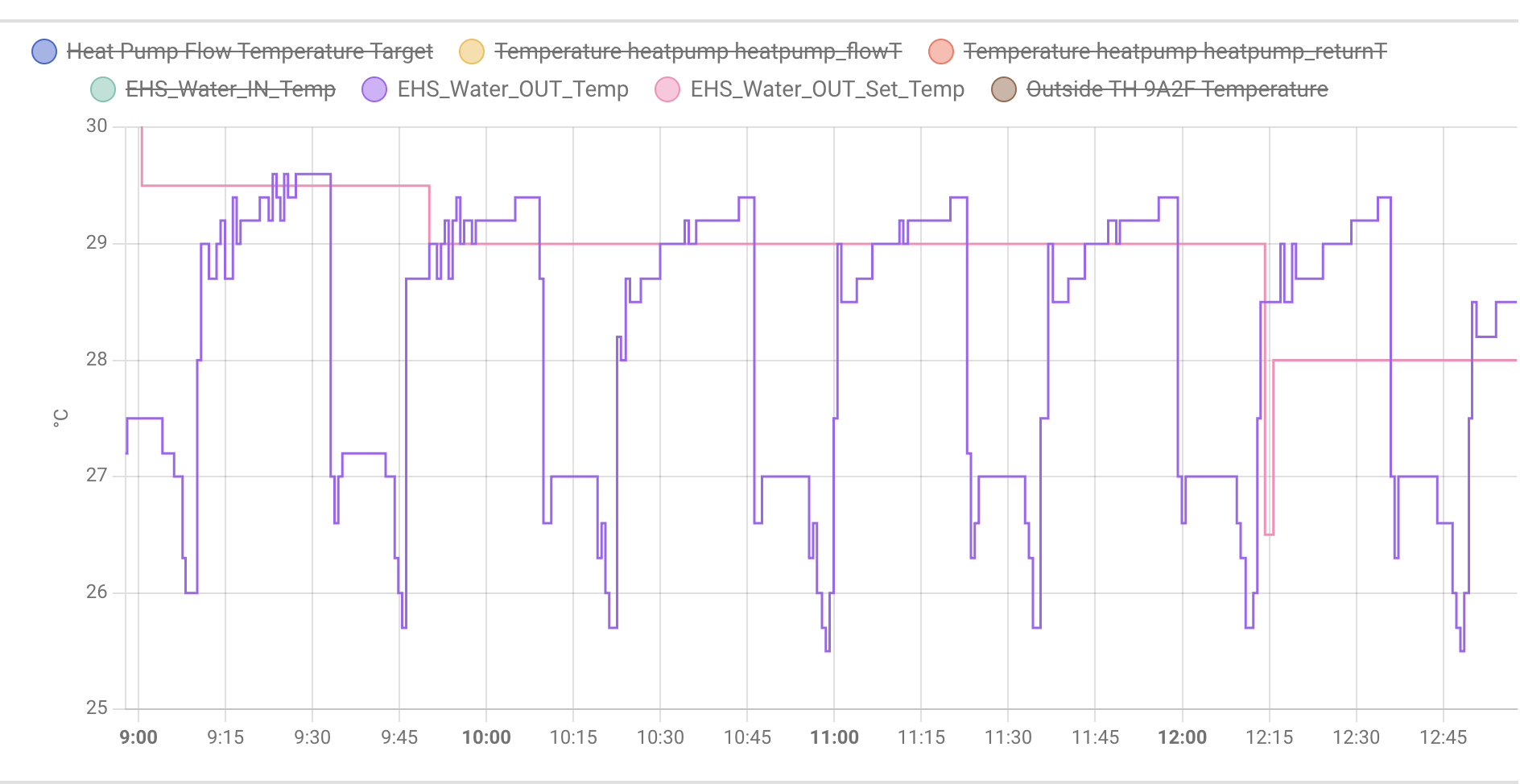
Couple of things
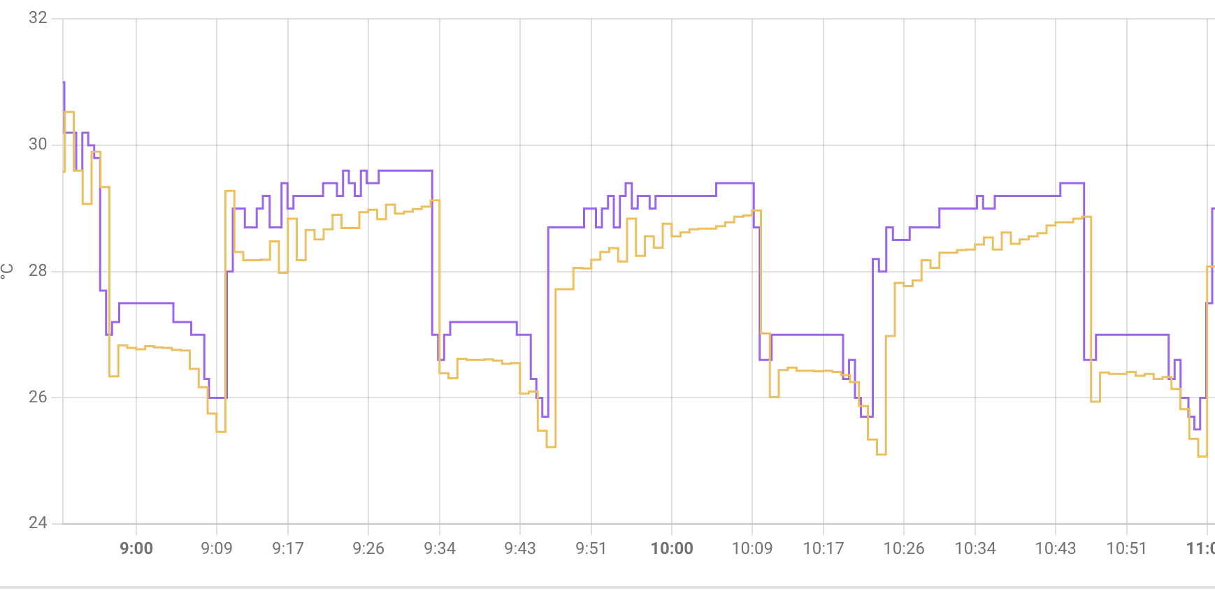
Flow
Yellow Emon
Purple Samsing (higher line generally for Colour blind)
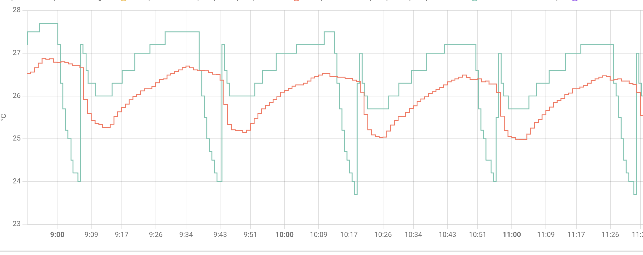
Return
Red EMON
Green Samsung (higher and not smooth)
I will set the target temp on emon to the set out temp but its going to be 2c off.
Seems the unit will do 22-24 minutes above the target temp, no mater what I set the target temp to
Its been off 12m on 23m all morning. House temp is rock solid -+ 0.07c
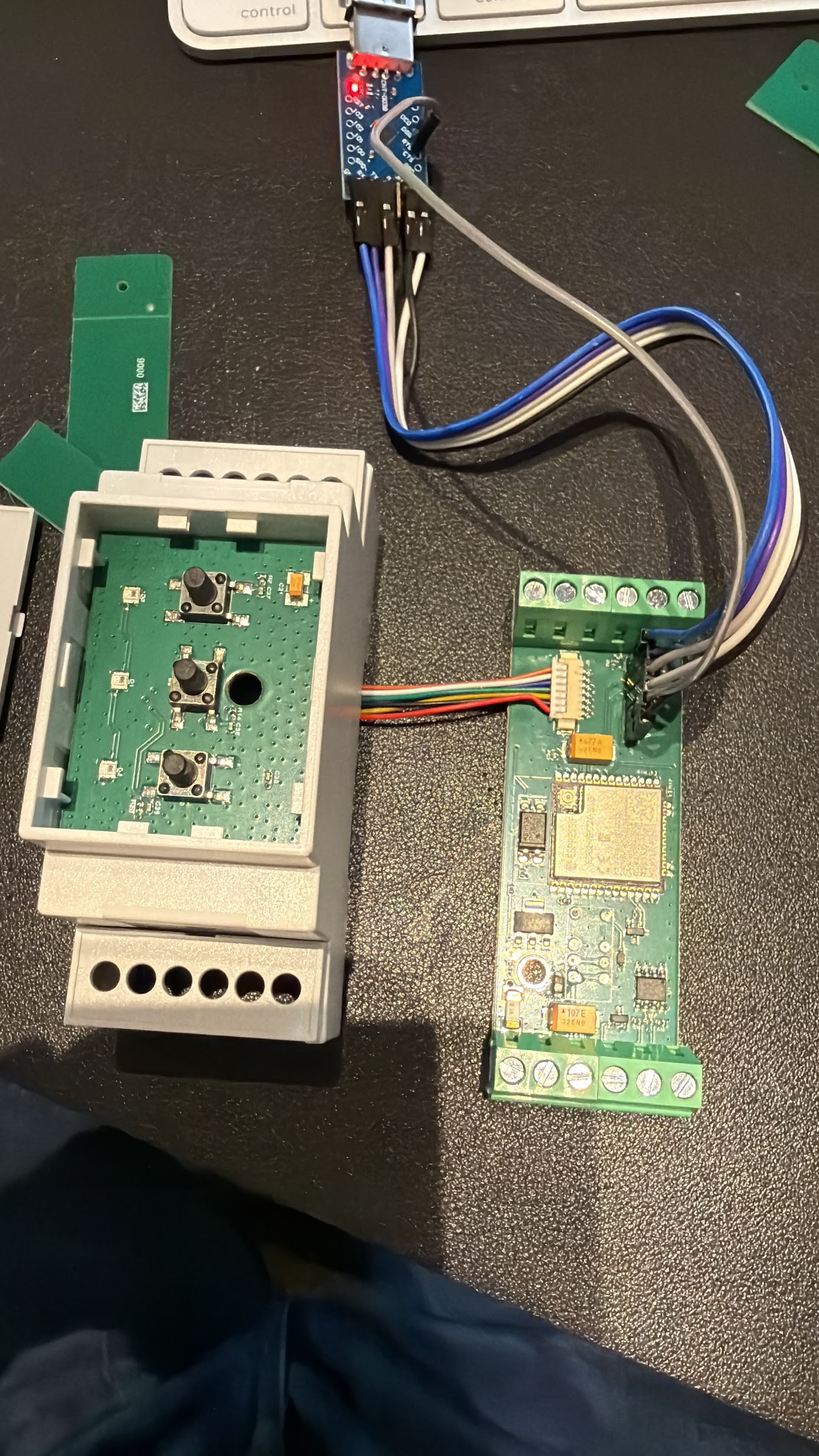
My controller connects via modbus. I keep getting distracted from building it and optimising my own house. It works like Homely does but I wanted it actually optimised and more customizable. I will be prob looking for testers soon but at this rate might be next heating season ![]()
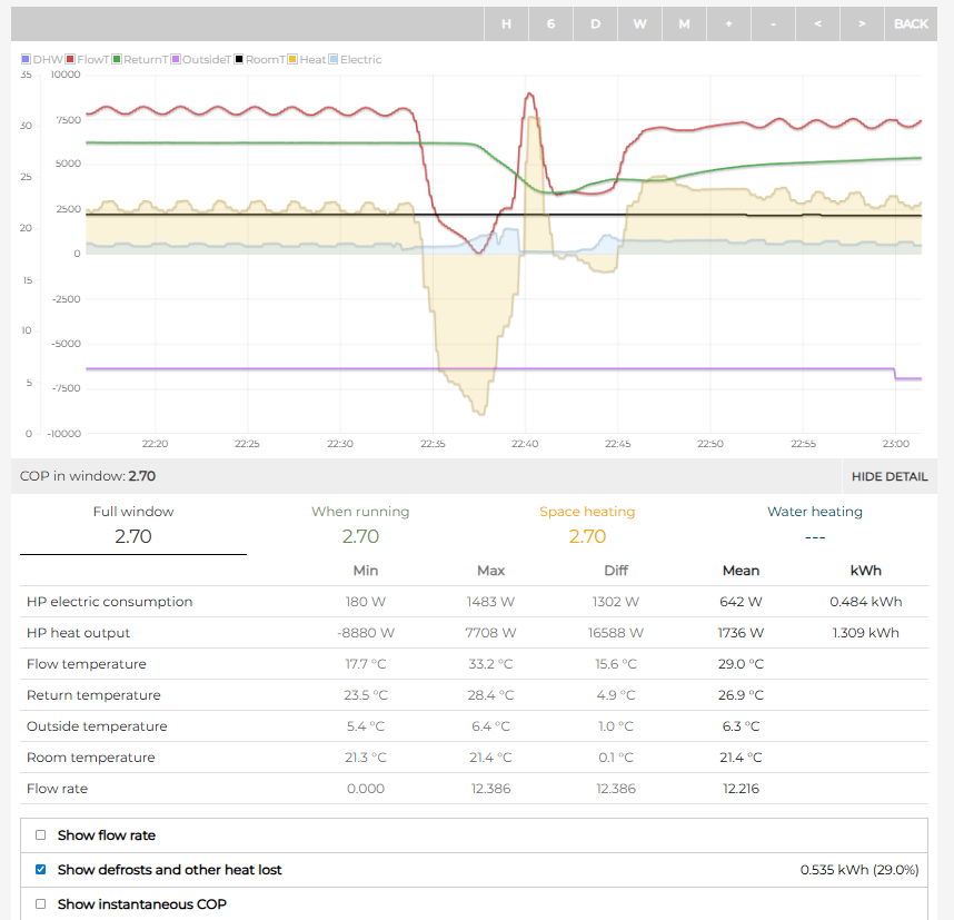
Has anyone noticed that raising the target LWT suddenly can cause a full on defrost cycle to happen even though it isn’t frosted up at all??
I’ve been manually lowering the target by a degree for a night time setback and raising it again by a degree. This morning I decided to raise it by 2 degrees and it caused the unit to run a defrost cycle. It was 10 degrees outside. This isn’t the first time I’ve seen it do this.
My worry is that when I use the smart grid feature to raise and lower the target temp (which I’m going to set up in the next week when my relays are delivered) that it’s going to do this every morning as the the minimum you can raise the target LWT by with the smart grid feature is 2 degrees.
The defrost only last 2 mins, instead of the usual 6. But was still taking over 6kW of heat out of the property for a while.
No, I’ve never seen that. How did you adjust the LWT? Did you use the +/-5C manual adjustment on the home screen to increase the LWT?
I’ve manually increased LWT by +5C before when Octopus were offering free or negatively priced electricity. I think I would have noticed a defrost cycle (or at least LWT not increasing as expected), although I don’t have monitoring.
Remember thats just power not energy, Looking at your graph while annoying its was 0.094 kWh.
Saying that ive not seen the my unit do this before.
Confirming my manual switch solution worked last night. OAT was forecast to fall to 4C overnight, and we turned the heating off when we went to bed, and activated the switch to keep B18 powered and maintain the 3-way valve in the space heating position.
Come morning, the DHW tank temp was intact and hadn’t fallen excessively overnight, so problem solved for me.
I’ve just received a plea from Samsung UK Helpdesk for data that supports our complaint about the algorithm that swipes heat from the DHW circuit during frost prevention cycles. It rather sounds that they haven’t been kept in the loop by HQ about the firmware update that @arundalep noted in Contribution: Samsung ASHP NASA link <-> MQTT bridge (Home Assistant) recently. But I’ll pass on their request anyway. Their email asked:
Hi Sarah,
Regarding the complaint of DHW temp dropping due to anti-freeze logic, do you or any of your friends off the heat pump group have any data showing the cycle removing heat from the DHW tank.
I’ve seen this before but I cant find the screen shots sent to me in my archive and wondered if you could help.
Best regards
Nick Kirwan
Technical Support Engineer
It rather sounds like HQ may have finally woken up to the problem and want some real data to justify some corrective action. So here’s our chance to influence Samsung! If you have data that proves that this algorithm wastes energy (@Michal_S you may be able to help here) please contact Nick at [email protected] directly.
Just for background, here’s the email I sent to Nick:
Morning Nick.
You may recall that I moderate a heat pump owners discussion group, many of whom are Samsung owners.
Amongst them, one of the biggest collective gripes with the MIM-E03*N controller is the frost prevention algorithm (the one that operates the circulation pump for 5 minutes if it has been idle for an hour and the ambient temperature is below 5degC).
The complaint is that the 3-way valve is energised, so heat is taken from the DHW tank rather than the emitter circuit. This can result in a cold DHW tank by morning, just when hot water is required for showers etc.
This algorithm is especially galling to those of us who have glycol in their emitter circuit, so frost prevention is unnecessary anyway.
The Samsung position is that the DHW tank is a better heat reserve than the emitter circuit (likely higher capacity and hotter). Yet folk who do not have a DHW tank connected to the heat pump (so there is no 3-way valve), and with no installed backup heater, seem to live quite happily preventing frost by using heat from the emitter circuit.
The widespread plea is therefore that Samsung introduce the option of taking heat from the emitter circuit if its volume is adequate (e.g. a volumiser is installed) or glycol is present. Clearly, enabling such an option should only be available to qualified installers and “sophisticated users”, so simply adding it as a remote controller setting may be inappropriate. I’m thinking that maybe adding a K-button option on the Outdoor Unit panel (which most users would not contemplate using) would provide sufficient protection from inadvertent use.
My discussion group would like to put this suggestion to the engineers at Samsung HQ but don’t know how to go about this. Can you suggest a suitable approach?
Thanks and regards,
Sarah