Samsung Gen6 and anti-freeze pump cycling below 5C OAT

Yes, this is it.

This is the guide for 2092, but I believe it is the same for 2093. Always on is setting 3.

You would need a software update, or you could just order a new PCB, like @SarahH.

It sounds like your default hysteresis is only 1 degree. Which is why it keeps starting immediately after stopping. LWT drops a few degrees when the compressor turns off, and it then starts back right back up.

Correct, my hysteresis is 5.5. My default is +2, and I have set 1063 to 3.5, so 5.5 in total. Target LWT was 26 (which is my low WL setting) compressor turns off when LWT reaches 28 (+2), and turns back on again at when LWT reaches 23.5 (-3.5).

Thanks Jake.

Thing is in #2093 I have these items:

Room Temp. only ON/FF I guess this is - 1

Room Temp. ON/OFF or WL Interlink ON/OFF(Water Pump1) - I believe this is 2

Room Temp. ON/OFF or WL Interlink ON/OFF(Water Pump2) - I believe this is 3

Room Temp. ON/OFF or WL Interlink ON/OFF(Water Pump2) - I believe this is 4

So I guess for pump on all the time I need to choose Room Temp. ON/OFF or WL Interlink ON/OFF(Water Pump2) or am I understand this incorrectly ? It’s confusing in FSV settings.

So really I need either software upgrade or a new PCB. What exactly needs to be updated ? MIM controller or something in outside unit ? What about wired controller ?

I could ask supplier if they can upgrade it for me. Or other new PCB.

@SarahH how much was the new PCB ? it’s something in outdoor unit and hard it was to replace ?

Yeah, seems it’s really 1 degree - in total ? so above +0.5 and below 0.5C to start or it’s 1C above and 1C below target to start ? How did they think it was a good idea ? when you stop the compressor everyone’s flow temp will drop by few degrees. I can’t understand this logic to be honest. Even yours - I believe you have UFH and as you stop the compressor then the flow temp drops instantly by 4 - 5C.

I wonder what settings @SarahH exactly do you use for this #2091 @2092 and #2093. You have external thermostat I remember but then what settings do you use 1, 2, 3 or 4 for the pump behavior ?

Correct, my hysteresis is 5.5. My default is +2, and I have set 1063 to 3.5, so 5.5 in total. Target LWT was 26 (which is my low WL setting) compressor turns off when LWT reaches 28 (+2), and turns back on again at when LWT reaches 23.5 (-3.5).

So you’ve set #1063 to 3.5C. Your target was 26C and it stopped at +2C so 28C and started again at 23.5C but this is 2.5C from target temperature, not 3.5C or ? Also why it stops 2C above and then 3.5C below ? Why this asymmetry and where it is configured ?

Thanks to both, it’s very appreciated.

I see what you are saying now. Then yes. I believe you are correct.

Just the MIM controller.

She said around £180 in total.

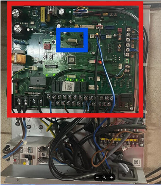
It is just this PCB (red square).

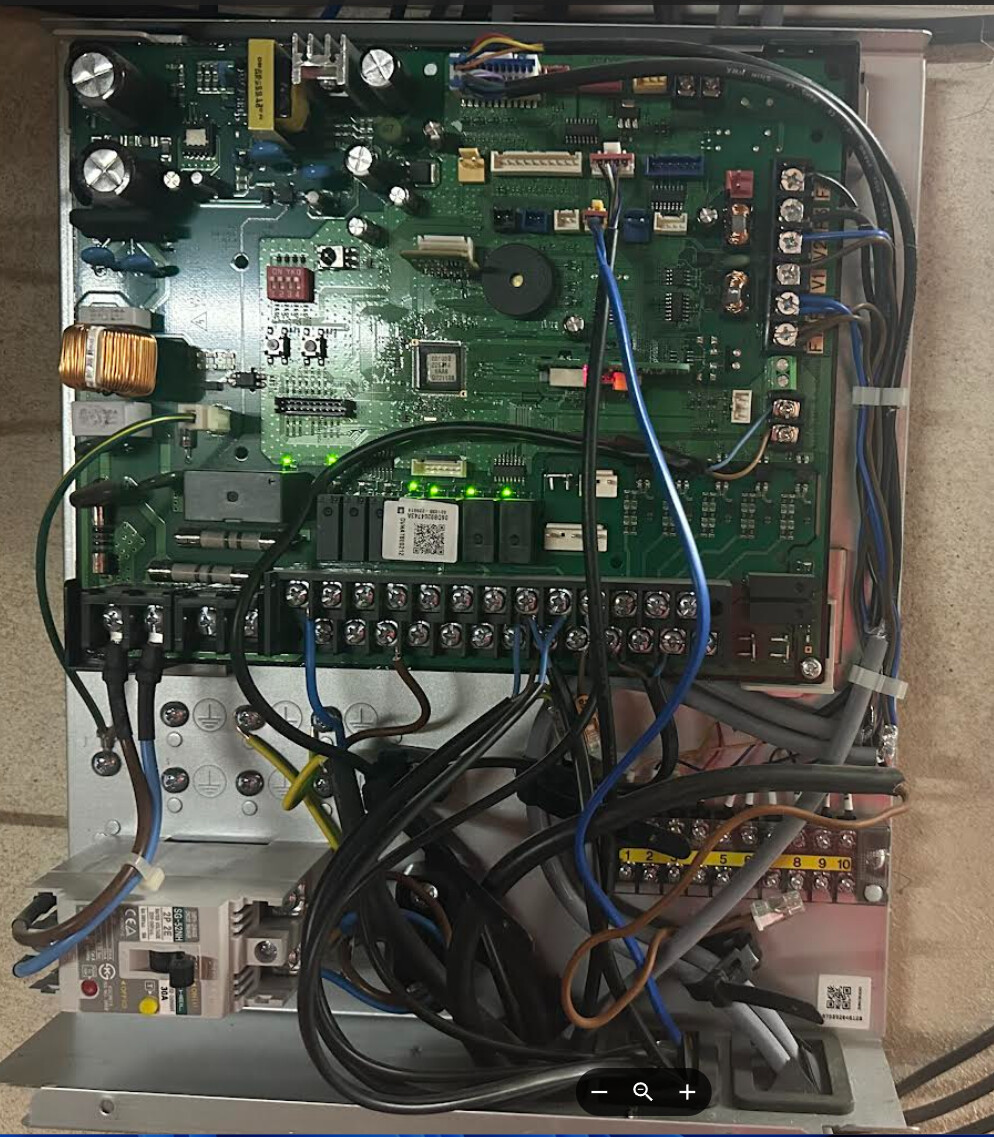
I did it myself when Samsung sent me a new PCB under warranty as my PWM wasn’t working. Power it off, unplug and unscrew all the wires, then it is held on with 2 screws to the casing. The Eeprom (which is the little PCB sticking out in the middle - blue square) just pulls out and will need plugging into your new PCB, as this isn’t included with a new PCB. I still have the old PCB, but this won’t help you as it didn’t have the 106* settings either.

I have no idea, but at least they got round to resolving it. Hopefully they do the same with our other issues.

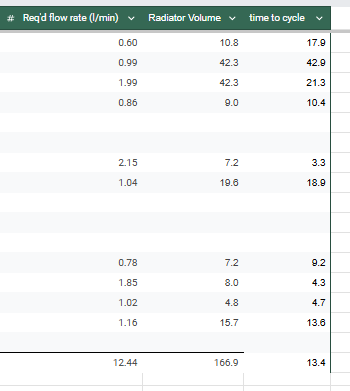
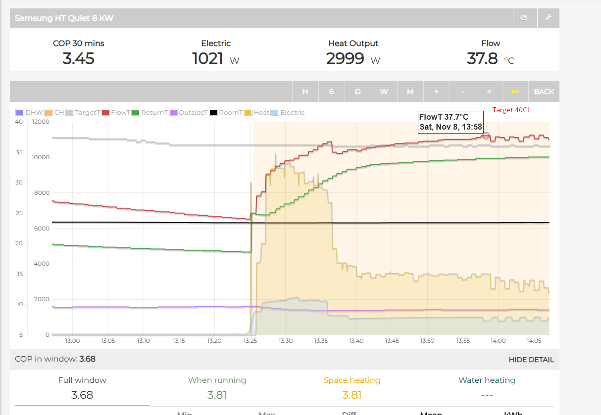
I only have rads, but some large ones, so around 200L volume in total. But yes, it drops around 4 degrees.

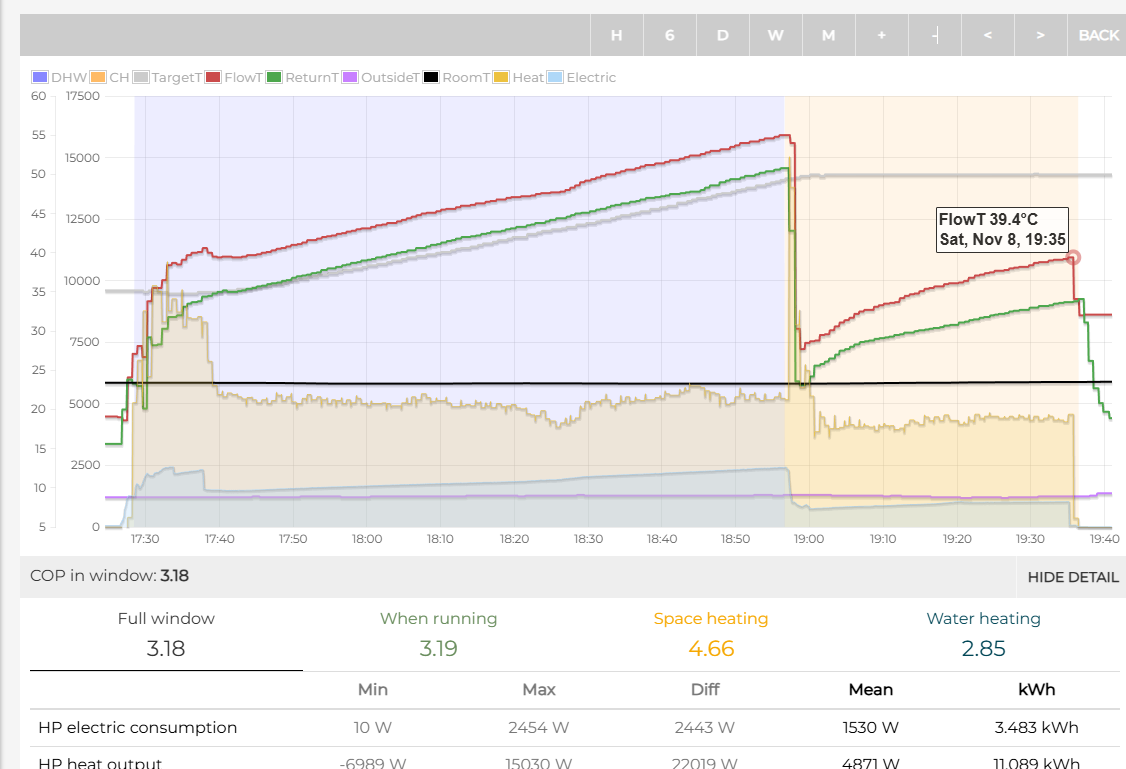
I have #1061 set to 3.5. #1063 controls indoor temp hysteresis, not LWT hysteresis.

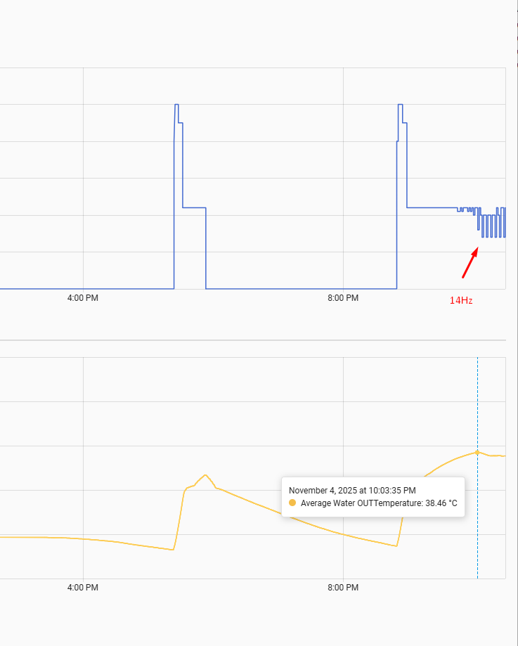
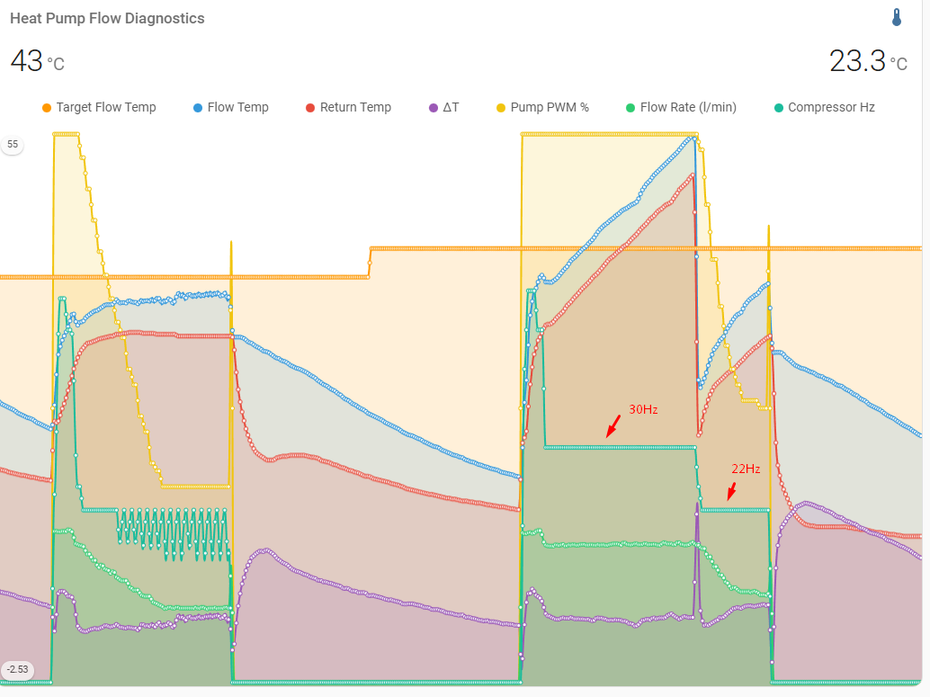
apologies, this must have been a typo. I meant it starts again at 22.5 But also, these are not reading from the Samsung unit itself, they are using the Open Energy Monitor kit which is around 10m downstream of outdoor unit.

The +2 cannot be changed, the only thing I can change is how far below target LWT it drops before starting again, which is #1061. I used 3.5 as it gives a total hysteresis (5.5) that is higher than the 4 degree drop when the compressor turns off, and also gives it enough time to drop even further so that when it starts again, it does not immediately go above the target LWT.
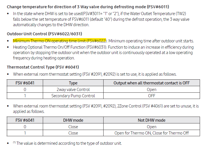
With the MIM update, you also get a minimum thermo on, FSV #6022, which I currently have set to 20 mins. So even if it did go above the +2 hysteresis in under 20 mins, it would stay running until the 20 mins have elapsed. Although, because I let it drop to -3.5, it rarely reaches target in less than 20mins.

Do not read too much into #6011, this is for defrosts only. Not AF cycles. I tried this already :wink: though I might double check.

I do not understand #6041 at all.

Can you tell me when exactly it is ? I can’t see any red squares or blue squares here.

That’s pretty impressive flow temp for rads :slight_smile: 200L is nice, I believe I have much less with my T21 types. I think I was computing it was like 60 L for the whole system while radiators have around 50L. Not that much right.

This looks interesting. Wish I can set min thermo off time, can’t believe it’s not there. But min compressor run time is also not that bad especially when used with thermostat.

#6041 - no idea but guess SaraH would know :slight_smile:

Apologies, i must have forgotten to paste the image before.

I specifically went for large radiators to be able to have low flow temps. My WL high setting is currently set to 38C at -3C outside. But I think this is a bit high and I might be able to get away with around 36 or 37C.
I have 2 large triple column vertical radiators that have a 3kW output at dt50, and they have a volume of 42L each. I have 2 other smaller column rads and the rest are T22. 10 rads in total.
1 of the large column rads was put in purely for looks, it is way too big for the room (in terms of output) and so only has a flow rate of 1lpm, so takes over 40min to completely cycle the water in it. 1 of the T22 rads in my kitchen takes only 3 mins to cycle all of the water in it as I run it at a high flow rate to get a low dt and marginally increased output.

Give me a chance, @Michal_S, I’ve only had the new PCB since Sunday and haven’t studied the manual yet!

But from a quick glance (I’m busy on other stuff at the moment), @jakeymd1 is quite correct in most (if not all) of what he has said. I had to replace the whole PCB because of the damage I’d caused. Helpdesk knew I was trying to acquire FSV#1061 etc, so gave me the part no. for the Rev 01 PCB update (DB92-05469A) and a list of suppliers:

Heron Hill had one in stock (Ā£180 including carriage and VAT), and I was in a panic so I looked no further. It took my installer about 30 minutes to put the new board in, but you could easily do it yourself if you are confident with static management and straightforward wiring. I gather that the all-important Micom is the square chip in the middle of your photo, where the BIOS resides. The EEPROM is just above this (you’re looking at it edge on in the photo), and as @jakeymd1 says, this has to be transferred from your old board to the new one, as it has all your prior settings on (like your FSV values, and other preferences like Quiet mode/Outing mode etc.). I think its the BIOS that stores FSV setup information and that it is this that determines whether your have FSV#1061ff available. If this understanding is correct, then you will need a whole new PCB to access the new FSVs (you can’t just change the Micom chip).

It sounds like @jakeymd1 has dealt with most of your questions already, but is there anything I can help with (like our comparing FSVs)?

Yup, I’ve copied it into the original.

1 Like

Thanks. OK let me see if I can find someone who can do a firmware update with the tool or I have to buy a PCB.

Take your time :wink: This #1061 is a must for everyone! I can’t understand why Samsung does not support firmware update remotely. Via APP or something, it’s unbelievable. I need to call a serviceman to cash out 150 eur or how much to do a stupid update.

You had pretty a lot of suppliers but I have to find someone in Europe - Slovakia or Germany preferably :slight_smile: In worst I have a family in Leicester so they could order it for me.

I’m an electrician so it should be not a problem to replace it for me. But still I would rather do firmware update, it would be cheaper.

BTW, do you know if it somehow possible to factory reset everything? I wrote lot of modbus registers so hopefuly haven’t screwed anything but the values I’ve stored persists after the pump is restarted. SO I would do a clean reset to see if the issue with pump resolves.

Jake said it is recommended to restart the pump after changing #9031.

Do you mean just software update is not enough ? I need the board for 180 pounds ? Sorry, not sure if I understand it correctly.

To ALL: So I can’t get it. #2093 is set to 3 - why the pump is still heating ? It obviously struggle to reach target temperature 39C. I’ve set it to 39C for test. It is going fine until 38.5 and the it starts to decrease compressor speed instead to turn the heat off by WL. Can anybody explain it ?

You can see that it reach 38.5C and then because it started oscillations to 14Hz it decreased on average to 37.7C which is 1.3C below target. I will never understand this pump… never.

@Topaz I have tried to manually use Test Mode as a workaround to the AS cycle.

Placing the system in Test Mode prevents the AS cycle from running as it seems to lock normal operation. When the AS cycle then fails to run, the system gives an E911 flow error as the pump(s) can’t start.

If you are lucky enough to catch the beginning of the AS cycle and then enter test mode, it will turn off the pumps and lock the system. Like you say, leaving in this state for 5mins or so, and then exiting Test Mode effectively prevents the AS cycle from completing.

I have also tried entering Test Mode, and manually run the pumps for a few mins to try to reset the 24h countdown timer since the pumps last ran. This only seems to work on my Gen6 system if the 3-way diverter valve is also in the DHW position, which defeats the purpose somewhat although I only need to run them for 10 secs instead of 5 mins AS cycle.

My knowledge of electronics terminology is feeble at best, but I gather that the FSV configuration (i.e. which ones are available to us) resides in BIOS (i.e. in the Micom), but the FSV values (i.e. their settings) reside in EEPROM (which can be replaced standalone). If this is correct, then it seems to me that only replacing the Micom (in effect, a new series 01 PCB) will get you the new FSVs. This reasoning is borne out by the observation that the only folk I’m aware of who have the new FSVs (mainly @jakeymd1 and me) also have new PCBs. I’ve not heard of software updates being able to do this (though I’d be happy to hear otherwise, anybody?).

This is clearly an issue. As the MIM controllers are cross compatible, you could order a brand new Gen 7 unit install today and be sent an old MIM controller that has been sat on a shelf at a resellers for several years (which is probably what happened with my Gen 7 install back in November ā€˜24)
I understand why Samsung would want to clear out old stock instead of spending all of the money to replace the PCB in MIM controllers around the world that resellers are holding on to. But for customers, you have no idea what you’re going to get.
Most customers probably wouldn’t notice or care, but I would argue that this is a fundamental issue with the old PCB rev - not a QoL update.
And what next? What happens when/if they provide further updates? New PCB again?
I really can’t recommend Samsung to anyone anymore. I’m beginning to sound like @Michal_S so I’ll stop ranting now :joy: .

1 Like

Oh Jesus, this is just too much. So Gen 7 R290 pumps with old controller ? Is this really a thing ? This is another nasty practice of Samsug but because of their false advertising my pump is 8KW (We all know it’s 14KW crippled out) I wouldn’t be surprised if this is the truth as well.

I’m not sure if exchanging the PCB would be worth of it then. Seems software update would be worthless but still I can’t get it. Why do we need new PCB to just have some field settings ? Then what firmware updates are good for ? Why can’t we do it OTA ?

I think I’m giving up on this pump. I spent too much time fixing the shit which should work out of a box and don’t want to waste any more time. I will wait until it dies and then will buy monoblock from some trustworthy brand, install myself and be happy finally. And I will be extremely caution what I’m buying this time… Issue is I don’t know how long this pump will last so it can be years or even decades lol. This is a thing you can’t simply sell someone and buy something else… This pump is simply too oversized for my tiny system and obviously Samsung didn’t tune it or allowed tuning for such systems. Yes with new controller it could probably be better but is it worth of it ?

I can second this.

I beg your pardon :smiley: This is not rant. It’s simply true fact but because 99% of users has no idea about heat pumps and how they work so of course they do not complaint. That does not mattery it’s not a shit :slight_smile: You can buy a cheap pump from Poland for 1500 eur and it maybe works better than this Samsung :slight_smile:

I’ve reversed the pinout of the dowbload connector in the ww10n wired controller, I’m pretty sure I can do the same for the dowbload connector on the MIM controller.

That would only require the .hex file to flash in (the one with the support of 1061) and a jtag adapter.

I’ll try on my setup first to see if I can provide with a reproducible way to do it.

This download connector is probably the way Samsung use duribg production of the boards.

Cheers

Too bad the AS cycles ends up in error when activating test mode. I’ll see if I can’t find another way to prevent this.

Thanks for your efforts

@Topaz I think you may be onto something, and more testing may be required.

I’m not sure if the flow error is only triggered when I put the controller into Test Mode before the AS cycle, in anticipation of it running - so the system tries to start the AS cycle, cannot start the pump(s) as in Test Mode, so fails with a E911 flow rate error as there is no flow.

Once an AS cycle has already started, if the system is then placed into Test Mode (for 5-10mins), I don’t recall seeing an error and it prevented the AS cycle from continuing for the full 5mins.

Once I tried leaving in Test Mode overnight, to prevent AF from running, and the controller locked up and needed a power cycle to restart, presumably to repeated failures/errors.

Hum interesting.

The continuous restart / failure, is something advertised in their manual. When too much flow error occurs in a row. Then the controller requires a restart.

However, I’ve never tried soft reset instead of powercycle!

Cheers

Yes, this is how Samsung works. If there is a flow when Samsung does not expect it it will throw an error. I think still the best solution is a relay :slight_smile: Until Samsung will hear us and let us to choose the source for AS.

BTW, do you thing something is broken in my controlling software I really can’t understand why the pump start to slow down then compressor when I’m still far away from target… My target is 40C and it starts to oscillate at 37.7C. Can’t get it I thought it’s only like 1C below target or so. Sometimes it’s just 0.5C.. Can’t get it, wish I can set a minimum compressor frequency for this thing.

Are you in quiet mode? This sometimes keep the flow temp just under the target flow temp in my experience.

Nope, but I do have frequency ratio control enabled. I don’t know how exactly this works because on controller you can’t set percentage so I would say it is set to 0 meaning compressor is using 50% of max power ? I don’t know but hour ago it was doing DHW and immediately after it was doing space heating and this was pretty good run :slight_smile: But I’ve increased target temp to 43 so the pump has no reason to lower compressor frequency and it was running steady at 22Hz… Water was heating at 30Hz.

So this (last run) is exactly I would like to see all the time but seems most of the time the pump behaves erratic changing compressor frequency like crazy once approaching the target temp. Look at the previous run. The erratic behavior started at 37C while target was 40C. I have some suspicion that’s because of low water level in my system. It’s around 40 - 50l so I would say pump is panicking somehow since the flow temperature is raising too fast and drastically changing the speed instead of smoother modulation. Or it’s simply stupid PID controller I don’t know. I’ve also set target deltaT to 6C. I’m thinking about buying 50L buffer tank to double the system volume which could help with this. Or maybe not, I don’t know.

What issue do you think the changing (up&down) frequency is causing?