Ah that’s cool, I didn’t know this was possible. Thanks ![]()
Hello Sarah. After a summer of tweaks and installer revisits to fit normally off valves to the supply and return, the hp working fine in what was a warm, dry autumn here in Slovakia, we’ve now had a few weeks of freezing nights (-1 - -6) and + 4-6 in the day. And now snow. As I’ve agreed previously with you, the manual has a steep learning curve, and it really takes something not to be working as expected to get an appreciation of what a particular FSV or set of same really do.
Anyway, things seem to be working ok, except for the dhw. This was fine until the colder weather, but the key issue seems to me to be the defrost function. Has anyone gained any understanding of how this function is controlled? Because the key issue is that very soon after a scheduled dhw demand and the hp gears up, it often goes into defrost mode, extracting heat from exactly the place in our heat store tank (800l) where we’re trying to put it! Now clearly the hp cannot know what future demand might be, so can’t defrost before the change to dhw function, but it would make sense to me, if a defrost is called for, that the diverter valve was turned back to heating mode for the period of the defrost, and then returned to dhw for continuing heat to the water. I can’t find any mention of defrost in the manual. Any ideas?? Thanks, Andrew
Hi again Andrew, and glad to hear that you have managed to tame your system somewhat ![]() .
.
- I’m afraid I can’t really help you with defrost diagnostics (I don’t continually monitor my heat pump). I’m sure you will have read the Defrost cycle Samsung Gen 7 8Kw thread, which includes the Samsung controller logic I posted (but which makes no sense to me).
- There are n! references to “defrost” in the OEM Search function, some of which (e.g. Daikin: Defrost cycle pulled heat from DHW) indicate similar observations on other vendors’ HPs. It might be worth trawling through these for clues.
- The one thing I do know about Samsungs (courtesy their UK Helpdesk) is that “During defrost energy is taken from the part of the circuit in operation at that time, heating circuit during heat operation, DHW cylinder during DHW operation”. I can only speculate that in your setup, the DHW cycle is actually provoking a defrost (though I can’t explain why this might be - I’ve had a look though my MIM-C02N outputs for space heating runs and DHW runs and can’t see any obvious difference in Outdoor Unit operating conditions for each that might explain the defrost kick-in.)
- Now that it’s getting colder I’ll try to gather some more Outdoor Unit data using the MIM-C02N, hopefully catching a defrost cycle, to see if I can reverse engineer the defrost algorithm. (The C02N outputs really useful info, but uses prodigious laptop memory so I can’t leave it running for long - maybe an hour at most - and catching a defrost cycle will be a matter of luck…)
Sarah
Thanks Sarah! Well I hadn’t spotted a thread on this exact subject! ![]() . A little light reading ahead…
. A little light reading ahead…
But on your point 3 - yes, that’s exactly my view, that it provokes a defrost. I should say that the hp runs pretty much constantly during the day (5.30 to 22.00 or thereabouts) when the setback on the ufh kicks in and elec use falls back to a low rumble. So when the scheduled dhw demands occur, I think the hp starts increasing output (55° setting from heating water law of around 34-36) the fins cool rapidly, frost up and bingo, it needs to defrost.
I’ll report back anon, after a lie down to read. Andrew
Hmm, not that simple, Andrew, I fear.
The evaporator inlet temperature (downstream of the expansion valve) tells the controller what the maximum compressor suction pressure should be to ensure 100% evaporation (by adjusting compressor speed and expansion valve position - one of the more important controller algorithms) but it (the evap inlet T) doesn’t know whether this is because DHW has been running, unless ![]() the controller knows that a DHW cycle has operated because of the 3-way valve position, and initiates a defrost just in case…
the controller knows that a DHW cycle has operated because of the 3-way valve position, and initiates a defrost just in case…
One of the things on my hit list to look at over winter…
Sarah
Hi Sarah,
Did you find Quiet Mode useful? I wonder what’s the max. compressor input and frequency for 8KW unit but I barely run over 50%. So debating to enable this and have it on all the time. Particularly it could help to keep HP more quiet on cycle start. I found at start it consumes up to 3.8A and then it stabilize at around 2.1 to 2.5A.But I don’t think this values are somehow trustworthy because 3.8x230=874W which is tad low. Or am I reading it wrong and I should compute compressor current with DC Link Voltage ? The it would give more sense 3.8x553=~2.1KW. But not sure how to compute power from.
The highest frequency I found was 51Hz at start of the cycle but not sure if this is max. frequency o r could get higher.
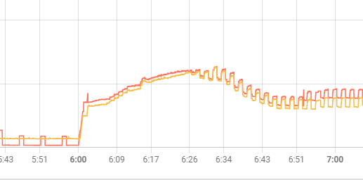
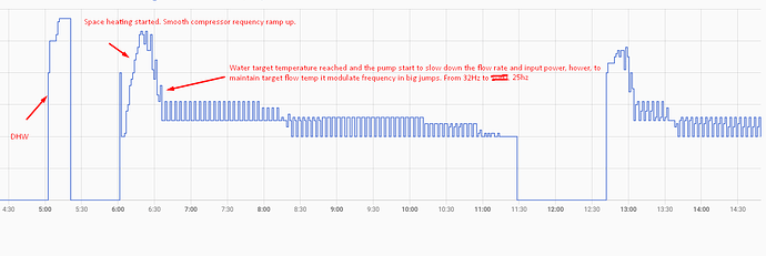
Also one additional question, do you have idea why compressor after initial run modulates frequency with 6hz steps producing this zigzag pattern?? I would expect somehow smoother modulation so not sure what’s behind this.
Thanks for insights.
Hello Michal, I can see that you have been very busy learning about heat pump anatomy for the last few months! It appears (other threads) that you have installed a MIM-B19 to gather data, some of which beg several extra questions…
- I confess I’m fresh out of insights on Quiet Mode, as apart from a couple of trials prior to writing the initial post in this thread, I haven’t used it. FWIW, my opinion remains that, by constraining compressor speed to ~60% of maximum it might 1) reduce the likelihood of noise complaints from your neighbours (or poor sleepers in your household) overnight, and 2) might make speed-intensive operations like DHW a little more economical, because of the decreased LWT required to reach cylstat setpoint (even though it takes longer to reach it). [In my case, I only heat DHW for less than 1 hour per week so the $ savings would be negligible, hence my inertia over any Quiet Mode optimisation].
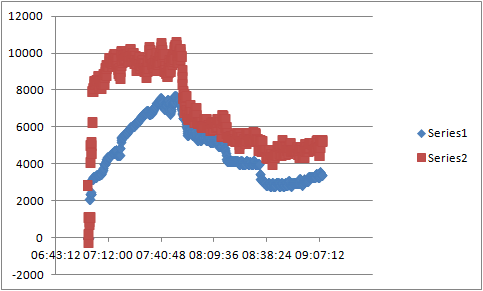
- Your question over HP power consumption monitoring is very timely, and I have repeatedly queried this with the Samsung UK Tech Helpline. The MIM-C02N reports “Compressor Current1 (degC)” (sic) with values that quickly rise to ~3 soon after start-up, rising gradually to ~7.5 (over about 40mins) [reaching a reported inverter frequency of ~57Hz, and a calculated thermal output of 10kW+ for an 8kW nameplate unit!] before falling gradually back to ~3 when the inverter frequency has fallen to the minimum 20Hz (a further 40mins or so). Now that doesn’t make sense - here’s a graph of “Compressor Current” (blue, x1000 so the y axis fits) and calculated heat output (red) after a recent start-up:
Hardly proportional, especially while the inverter is overspeeding (first 40mins). I suspect that the MIM-C02N is not reporting motor/inverter current at all… - My electrical engineering knowledge is non-existent. But 7.6A (the maximum value the MIM-C02N registered) x 250V (the steady mains voltage I measured on the day of this test) gives 1900W. With a calculated max heat output of ~10kW, that’s a CoP of over 5 which I do not believe, on a day when the ambient temperature was barely 0degC.
- I wonder if the MIM-B19 is reporting different results to the MIM-C02N? I saw the B19 output (different thread) and some of the numbers look inconsistent to mine (given that you and I have identical heat pump models). You mention “DC link”. Do you know what this is? I asked the Helpline and they didn’t… (It stays at ~180 throughout on the C02N output, and the reported units are degC, not volts.
- The MIM-C02N does not see the zigzag inverter frequency that your MIM-B19 reports - the variations are all gradual (though on my testrun they went up to 57Hz as noted above, rather than the 51Hz max that you saw…).
- On another matter entirely, the “BEK series” refers to the Samsung R290 Integrated option - the Outdoor Unit includes the circulating pump and controller - as opposed to the Monobloc version (DEK series) which requires a separate Indoor Unit or equivalent components.
Hope this doesn’t confuse things for anyone…
Sarah
Hi Sarah,
Thanks for your time to reply to me. Indeed, I’ve finally installed modbus and trying to understand the pump better.
-
This quiet mode is debatable. This night was 0C and from 00:00 to 06:00 I have pump off. This morning I could see 60Hz for the first time and from power reading this correcsponds to appx. 3500W which I guess is max power of this pump.
-
I wonder why Samsung changed the design with R290 gen. 7 (or gen. 8?) heatpupms. Do they install smaller compressor to smaller units ? This thing they’ve put same compressor to 8KW unit as to 14KW unit is fishy. Knowing that beforre I would probably but different pump because for this reason my HP is able to modulate only to about 750W which gives 3KW of heat with COP4 or around 2KW at COP3. Since at such low compressor speed and my rads combination this effectively crimple COP at higher outer temps.
-
This COPs I’ve found on midsummer wholesale
MCS Listed SCOPs
@35°C 4.46
@40°C 4.30
@45°C 3.98
@50°C 3.66
@55°C 3.34
@60°C 3.08
@65°C 2.82
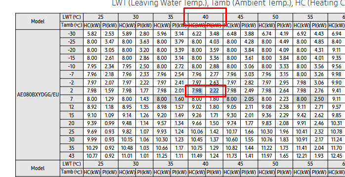
OK it’s SCOP but in specs I’ve found this:
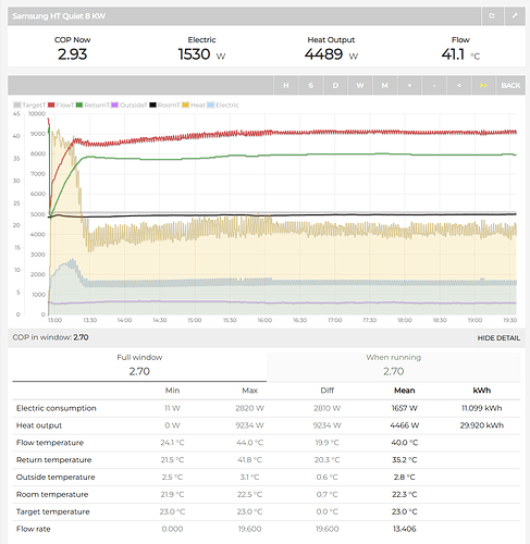
I wonder what conditions has to be fulfilled here because no way I can reach such COP. At 2C it should have 3.6. My COP for yesterday was: 3.03 - at least from what remote controller shows. Is it within tolerance ? I know those COPs are calculated in ideal conditions but whatever. At 7C it gives 4.4 but if I have 3.5 I’m lucky. My best guess it that pump is giving to much heat so it limits fan speed at minimum and with lowest non optimal compressor speed it negatively impact COP. OK, but I would not expect it around 0.
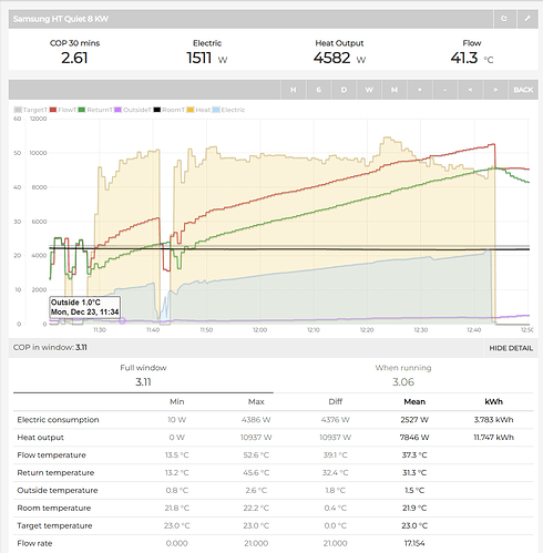
E.g. look at this graphs of flow temperature and outside degree for yesterday…
You may see flow is around 40C and average temp was 2C. So I would expect higher COP. Do you have an idea what could have impact on such smaller COP ? It’s 17% lower than expected.
- Regarding Zigzag pattern. This is really because of control kit ? I have MIM-E03CN and wonder why they’ve decided to go with this pattern ? Makes me nervous a bit, why it is not modulating more smoothly ? Or it’s a firmware bug ? Didn’t updated since installation. I can see smooth modulation only when the pump is starting for 30 mins and then zigzag starts to no end:
- DC link voltage no idea but it is changing values from ~450 to 600V. To be honest for me compressor current makes no sense. At 60Hz I had 5A which would be 5*230=1150W which is very low. At that time the consumption was around 3.5KW. But If I multiply with DC Link voltage which was around 550V this gives 2750W which is still to low so really don’t know what this compressor current means

Still too many questions unexplained with this pump ![]() What I like however, that is really quiet. Even on high compressor speed mostly air flow can be heard.
What I like however, that is really quiet. Even on high compressor speed mostly air flow can be heard.
Hi again @Michal_S,
How are you calculating your (low ![]() ) CoPs?
) CoPs?
If from Q = m.Cp.(LWT-RWT) it occurs to me that:
- if your flowmeter is poorly installed there may be an error in mass flow m
- if you have glycol the flowmeter may not have been calibrated correctly
- again if you have glycol you may be using the wrong Cp (and the wrong density when calculating m from the volumetric flow the flowmeter is producing)
- For (LWT-RWT) you are calculating a small difference between two large numbers, so if one or other (or both) temperature sensors are slightly out (say 0.5degC) and your DT is say 3degC , that could give you a 15% error in Q.
Errors may also arise if your compressor is not running at full speed - although in theory scroll compressors (being positive displacement devices) should follow (power ∝ speed), in reality losses - e.g. compressor leakage/friction, motor, inverter - may change with speed, so you cannot necessarily prorate the Samsung figures (which I assume are based on full speed) to other speeds.
As regards your zigzag pattern, it looks like your circulating pump might be cycling on/off for some reason. Are you PWM controlling your pump? If so can you try disconnecting the control signal for a while (so it runs at 100% speed) to see if the problem persists?
Hi SaraH,
I’ve posted it here somewhere, it’s computed like this:
No glycol but the flow rate is taken from HP flow meter so this is not super precise. Also in/out temperatures are from the pump itself. This way it gives slightly less COP than data in roomstat so I guess it is closer to reality ? With dedicated flow/temperature hardware it could be even worse or maybe better. Don’t know indeed ![]()
What it shows me is appx. COP3 at 3C o outside. Flow temp around 40 so can’t tell if it is poor, average or good.
Pump is running fine according PWM, what oscillates is the input power. I don’t know why it modulates like this but today I’ve installed DHW tank and I didn’t see such pattern. Put pump were run like crazy over 4KW in power at highest. Zigzag looks like it’s caused by control unit to keep water temperature at desired level but why it is doing by that dramatic pattern I have no idea. I can see there is some field setting in pump - control factor level, do you know what is that and what impact it has on pump behavior ?
Look at this screens.
1.DHW - system filled with cold water maybe around 10C, heated to 50C. Took 1:20. No fluctuation of power and input power increased slowly.
- Space heating.
Do you have some experiences with DHW and how it works ? Because I’ve set 50C and saw it reached 45.8C and turned off (Why did it not reach 50C but turned off prematurely ?). In 7h water temperature dropped to 43.6C. Do you know when the pump start heat water again ? Now it is heating space but now sure what triggers the pump to switch to DHW. Outside temp is actually 2.7C.
Thanks.
Hi Michal, thanks for the information.
- Yes that’s roughly how I calculate heat generated, except that I calculate Cp based on (LWT+RWT)/2 whereas you have a constant 70 (which assumes that Cp is constant at 4200J/kg/K). At 40degC average temp Cp for water is actually 4177J/kg/K, but that’s only 0.5% error – not significant.
- The more problematic factor in CoP calculation is power consumed. Do you measure it using a standalone CT on the Outdoor Unit supply, or from your MIM-B19 output, or read it from the remote display (Settings/Energy/Energy Usage/Instantaneous Power)? Unfortunately the MIM-C02N and SNET software doesn’t display this – it only shows “compressor current” which 1) appears to be inaccurate (I’m still trying to get clarity from Samsung UK on this), 2) requires a knowledge of supply voltage (and power factor) to calculate watts, and 3) (presumably) doesn’t include the power required for the fan and the electronics.
- I can’t tell from your graphs what is causing your zigzag on space heating, but I see that both your calculated heat output, and your power consumption, are swinging by ~10% every minute or so. That’s a huge variation, and one I just don’t see in the MIM-C02N output for my HP (which refreshes every 10seconds). Where does your graph data come from? And does your MIM-B19 output tell the same story?
- You ask about PWM control factor (FSV#4053). Samsung have stated that “New PWM value(%) = Current PWM value(%) + (LWT – RWT – FSV#4052) * FSV#4053”, which looks to me a bit like y = mx + c, where m is #4053 and x is the DT offset. If you have the multiplier m set too high you might get unstable variations in the PWM signal, but I would have expected these to apply equally to DHW heating (which they don’t)
 .
. - Regarding your DHW, 4kW is not unexpectedly high. If your LWT is 60degC (which is easily possible especially if your DHW tank coil is a little undersized) on a cold day (say 2degC) the Samsung data book gives a power requirement of 3.6kW (I assume at 50Hz compressor speed). I’ve seen a compressor speed of 57Hz before now on the MIM-C02N, and prorating the 3.6 by this speed ratio gets you to 4kW.
- Your questions about DHW hysteresis may be answered in the User Manual references to FSV#302x. #3022 is the temperature overshoot and #3023 is the restart DT. Also, if you have set #3025 too low, DHW heating may time out before you have reached the target.
Hope this helps!
Hi Sarah, Many thanks for reply. Your hints are very valuable for me.
That’s right, it’s a constant 4200J. So (LWT+RWT)/2 is better you think ? I can switch to this then, thanks.
The power is very precise because I use a dedicated 3-phase RS485 power meter connected to control unit and outdoor unit exclusively. So all what it measure is HP consumption. Interesting finding is that stand by is 10W.
So power consumption is not a problem. I’m more concerned about flow rate and flow and return temps precision and especially update interval. Since power input is realtime, flow and in/out temperature are reported with delay. And since power input in my system fluctuates like crazy I think there might be som discrepancies.
From what I saw is that this fluctuation is only with space heating. With DHW there is no such behavior and power consumption is slowly rising above 4KW… This is crazy power input, wasn’t expecting it like that ![]()
To me it looks like the way of control unit to keep average in/out temperatures at desired value but in a bit of drastic way. I don’t know if it’s because the pump PWM are not regulated fast enough or why the pump do some zigzag pattern. I think it must be some bug or what because indeed there is no reason for that but honestly I’ve seen it at other Samsung’s pump over here.
Why simply fluctuates by 300 - 400 wates every couple of minutes ? Whyit can’t fluctuate by 50W every few seconds ? I can’t get this. I have smooth curve only at start when input power ramping up but then as it start to decrease together with flow rate is starts doing this.
Granted you have different controller so probably there is some issue with mim MIM-C03EN.
Data are coming directly from pump via modbus, power input from dedicated power meter. But I have another one which measure the whole house and the pattern is the same so definitely this is compressor frequency jumping heavily. Check this screen.
I need your help with DHW cooling down during night. I’ve noticed this and I suspect that because it was close to freezing temperature, HP was starting circulation pump but with 3-way valve open to DHW circuit. This effectively cooled down the water in tank from 46.4 to 44.4C in ten minutes. Then one hour later again the pump is running and again 2C temperature drop. It is the way how HP ensures the water won’t freeze in pipes during low outside temperatures ? So instead of circulation water in UHF circuit it circulates DHW ?? This is new to me because when I didn’t have DHW it always circulated the UHF. I don’t remember if it was starting a compressor occasionally but now it is not starting the compressor at all but taking heat from DHW tank.
Is this behavior desired ? I can see indeed the flow temperature is rising during DHW temp drop so I guess I’m correct with this assumption.
For PWM I can select 3 values - 1, 2 and 3 and I have 2 now. So wonder what impact would have on a pump speed if I change it to 1 or 3 ?? What I’ve noticed that my pump always starts at 100% which yeleds around 20l/m. But when HP tries to lower the speed the percentage starts to drop slowly from 100,99,98,97,etc. Problem is that until about 75% there is no change in pump RMP speed so the flow is still the same. I don’t understand this behavior.
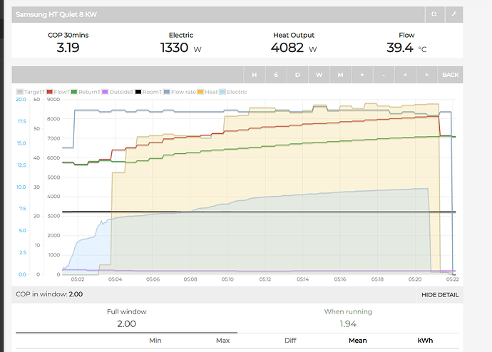
My coil is 2.9m2 and it’s 280L tank. So surface area of heat exchanger not that small. There are much smaller in market ![]() I’ve put temperature probe to middle section of a tank and found I have at the top the temp I set. So yes, I’m running 50C target temp but this is only at top, at bottom is maybe 40C. But yes, LWT temperature is attacking 60C. But still over 4KW looks pretty much to me. Here is the graph of latest run of DHW at night:
I’ve put temperature probe to middle section of a tank and found I have at the top the temp I set. So yes, I’m running 50C target temp but this is only at top, at bottom is maybe 40C. But yes, LWT temperature is attacking 60C. But still over 4KW looks pretty much to me. Here is the graph of latest run of DHW at night:
It was around 2C outside and it was heating water from 40C to 46.4. Max. flow 19l/m. At the end it was running at 4.4KW with flow temp 54.2C. It was running for 19 minutes. COP 2. Can you tell if it’s acceptable ? Is 19l/m flow enough or not good enough ? I have some susupicion of a TF1 filter causing high pressure drop because I’ve noticed I have the same flow on DHW as with space heating where space heating has 3 branches and running across 2 floors from cellar. Can’t understand why the flow is same, I have 28mm piping to DHW tank so I would expect a higher flow here. The only common is the 3 way valve and TF1 filter. Since before I’ve installed 3-way valve the max flow was also 20l/m I suspect it’s the TF1 filter placed on return before flow meter causing the issue ?
One update and interesting finding. I’ve found out that HP openeded 3-way valve to DHW just to heat the water in piping ? Why pump is doing this? Why it won’t user heat spacing circuit water ? I’m bit confused because this does not look like a good logic. Iven if there is cold outside (it was not freezing btw) the system only need to run pump to circulates water for short period of time to prevent freezing. But why it exclusively open DHW circuit to take heat from tank is unclear to me. Can I prevent this behavior somehow? Purple is open DHW circuit.
Thanks again for your time and insights.
Hi @SarahH, do you maybe have an idea what is FSV #4053 pump control factor for ? There are numbers 1, 2 and 3 but I really have no idea what they means. I have set it to 2.
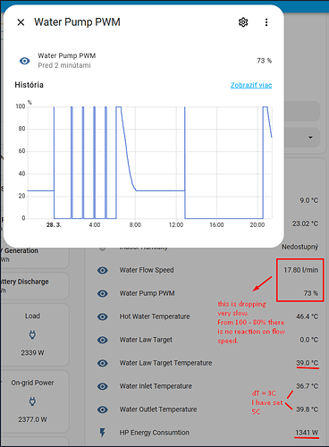
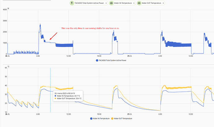
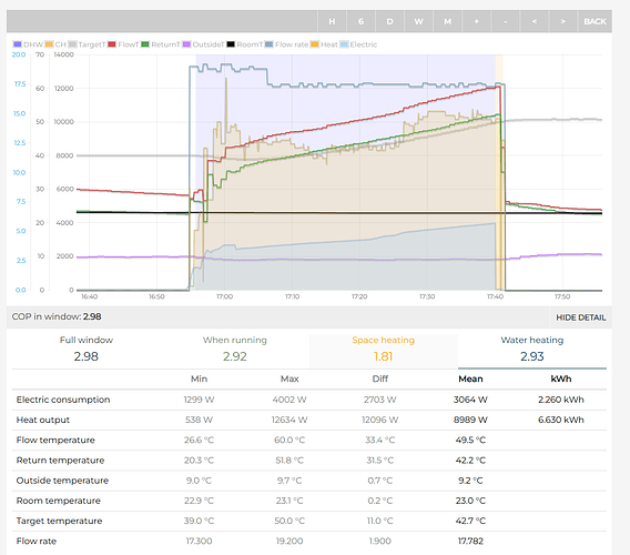
I somehow struggle that in warmer weather my dT is closer to 3, despite the fact I have this set to 5C. The reason is that when the pump starts it start with quite high power and it takes long time until pump PWM reduces from 100% to 25% which is minimum flow. It also overshoots my target water temp. Is there any chance how to make this decrease somehow faster. Or to instruct the pump to use lower power from beginning ?
Here the image attached. dT = 3. Unnecessary high power in my opinion. It’s 10C outside so why such high compressor speed.
Thanks for any insights.
Good morning Michal.
Samsung have told us that the controller applies the following equation for circulating pump speed as it parses the current input values to calculate new output values:
New PWM value (%) = Current PWM value (%) + [(LWT - RWT - FSV#4052) * FSV#4053]
As you can see, this is effectively applying a straight line correlation y = mx + c where the gradient m is set by #4053, x is the measured deltaT departure from the target #4052, and offset c is the current PWM output value. I’m not sure of the parsing frequency in the MIM-E03EN, but judging by the data refresh rate I see on SNET-Pro2 it seems to be about every 10s.
So in principle, the higher you set #4053, the greater the change in PWM each parse, thus the faster the PWM value will change over time (but at the cost of a potentially less stable operation, of course).
Having said that, I too see a very slow change in PWM output signal after start-up, and surmise that Samsung also apply an additional factor (which they haven’t told us about, but may simply be a timer) that inhibits the PWM rate of change after start-up.
Another one for your “Samsung mysteries” book, which must already run to several chapters I suspect… ![]()
You could try setting 4051 to max 70% in the months where you dont need more than that. That will somewhat solve your issue. I also have 4053 to increase how aggressively it chaces the target dt, as explained by @SarahH.
The flow rate will also only drop so far, mine has a minimum flow rate of 7lpm before it faults. Mine actually settles at around 8-9 as it’s minimum under PWM control.
I have also used a 3rd party pwm controller in the past during some testing, if you want to play around with your own PWM formula. I dont think it matters too much if dt reduces below the target dt, it still seems to run efficiently and compressor speed seems to become more stable at higher flow rates, which makes sense.
Hi Sarah, thanks, these is pretty interesting info. I’ve already set power factor to 3 to try it out so let’s see. Usually I only have issues when it gets warmer above 5 degrees. Then flow temp according weather compensation curve is too low. Often 35 or lower and here my system is very inefficient. I’d better need to run 40C flow and keep it cycling every couple of hours. I’ve already found a way with Modbus to manipulate that damn #2011 lower ![]()
So last time I’ve tried 3C/39C and -20C/60C curve with dT = 7C. Somehow pretty good COP towards approaching 23C indoor. 3.7 which is quite good with this system with low water volume and T21 rads. Simply this pump is oversized. Shame on Samsung this was not stated anywhere clearly it’s 14kW unit only crimpled. You can imagine me anger with Samsung. As I understood gen.7 with R290 does not have this false marketing and they can modulate much lower. Well, now I only need to live with this and suffer.
Thanks for hint. I’ve accidentally set this to 70% and the flow drop was much faster (together with control factor = 3). The Samsung is so stupid that it starts going from 100% to lower number constantly and slowly. There is no logic saying hey, there is no change in flow, let’s try to reduce the number faster or by bigger value. Jess. So you have to wait an hour until it finally go under 70% and starts to slow down the pump. Of course it will overshoot targe temp by one or 2 degrees. Really stupid pump, I said this million times (@SarahH knows lol).
I also tried to set dT=7C. I know this is not achievable with my system but somehow hope it will ramp down faster with flow speed ![]() Honestly this yield best COP so far with outside temps above 10C.
Honestly this yield best COP so far with outside temps above 10C.
Btw what kind of pump and system do you have? Seems similar to mine.
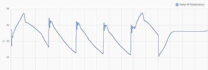
I wish I’ve bough Zubadan that time. It was in my focus but once again I did wrong decision. But I was fooled so not completely my fault. Next time I buying a pump I will require from manufacturer to provide min. power input it can operate with. This ones operates so unstable. Compressor frequency is jumping like crazy above and below 20hz almost always… Really pain to watch.
Here you can see while return temp is stable, flow temperature spikes like crazy.
Hi again, @Michal_S
Looking at your data I’m beginning to develop a theory about your rapid LWT cycling. It’s a bit controversial, but I need more data before I say more. Can you do an experiment for me, please?
When you have two prospective consecutive days with the same outside temperature, graph the data for RWT, LWT, water circulation flow rate, and compressor speed: On day 1 with your WL settings (#2011/2, #2031/2) as they are now, and for day 2 repeat the exercise, except with #2031/2 both increased by a significant amount (say 4degC higher than the day 1 settings). Change nothing else, including roomstat settings.
If you post your graphs on this thread I can test my theory ![]() …
…
Hi Sarah, sure will do so ![]() I’m curious if your theory will be confirmed but I think I know where you aim (and maybe not :))
I’m curious if your theory will be confirmed but I think I know where you aim (and maybe not :)) ![]()
Next days pretty stable temperature without the sun so this could fit our test…
Current parameters are as follows:
dT = 6C
Max. pump speed 70%. This is basically almost identical to 100% pump speed. There is quite huge dead zone because something is restricting the flow so even at 100% it can’t give full flow. So I’m having 18 - 19l/s max.
Min. flow is then 25% which is around 9l/s
Room target temperature is set to 23C with hysteresis +0.2C/-0.2C so the pump starts when indoor temp drops to 22.7C and stops heating when it reaches 23.3C.
Current WL settings 2C/40C and -20C/60C. So from 2C and above flat temperature of 40C is used.
Let’s keep these from now on until tomorrow noon. Then I will change #2031/2 to 45C/65C. Let’s see what happens. Obviously the pump will cycle much often, but let’s see how stable is it… Btw, when heating a water, this is good without throttling.
This is last run from 40C to 50C
BTW, if you are interested here’s the full data of my pump. Just note I’m using Samsung’s sensors for LWT/RWT and flow speed so it might me more or less precise…
Sounds good, Michal, but would you be able to manage without DHW heating for the period of the test? Ideally I wouldn’t want the distraction - let’s focus on space heating if possible…
BTW 18-19l/s?? I assume you mean l/min.
And 25% = 9l/min?? My calculator must have a fault…
Yes, sure. I will turn off DHW heating during our test.
Yes, sorry, my fault, wrong units ![]() It’s l/min ofc.
It’s l/min ofc.

