Samsung Gen 6 R32 5kW + Sunamp Thermino (plenty of questions inside)

Good evening everyone, I hope you are well.

I’ve been reading for a while but I can’t seem to find any answer to my questions. So my hardware is the following (I hope I don’t forget anything)

Samsung Mono Generation 6 R32 1PH 5kW
Sunamp Thermino 300L (not many people have this combination).
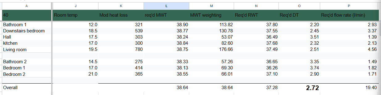
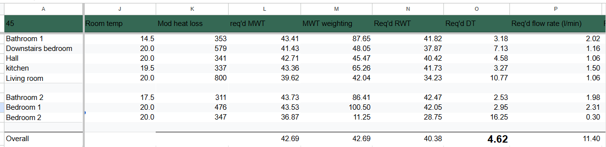
This was the initial heat/loss report

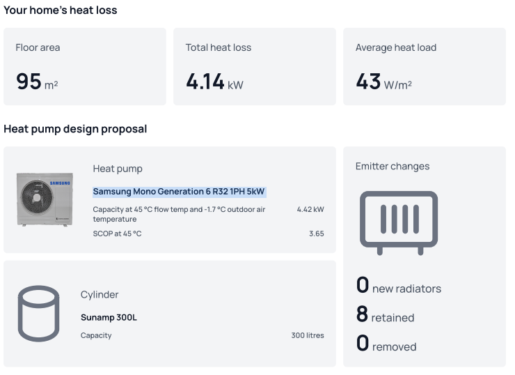
My radiators are as follows

Since the initial report I’ve upgraded the living room to a triple paneled one and the radiator in bathroom 1 has been changed with one that can output circa 530W so barely the room need. To be noted that the bathroom 1 had one of the window closed and isolated so the loss in that room is supposed to be lower now.

Ok so this is the scenario I live in. I have then the Samsung Wifi unit (purchased while trying to remotely control the HP) and then I have an ESP32 controller as well. Both connected to F1/F2. I use the ESP32 in home assistant to read data from the HP.

I think I’m using weather compensation (AKA Water Law) and I’ve set the curve as follows

20 Degrees Outside Temp > 28 degrees flow temp
-2 Degrees Outside Temp > 40 degrees flow temp
(All celsius)
This gives me a slope for my weather compensation function of -5.5 and a intersect point at 0 degrees of 39 degrees.

My inverter pump is set at use 70% and the form factor is set to 1. Dt in the inverter pump options is set to 5 degrees C

I use a nest thermostat connected to the internal Samsung unit as on/off. I set the temperature to 22 degrees and the pump will run until I reach that figure. It’s very unlikely so the HP is on basically 22 hours out of 24. in those 2 hours I boot the Thermino. Spoiler: during the winter it is not able to reach the needed 65 degrees so I have it run for 2 hours and then switch on the immersion heater.

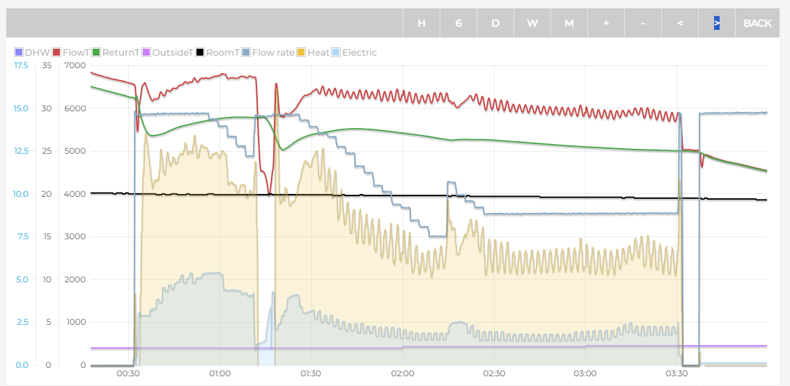
I have built the following dashboard in HA

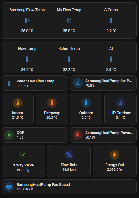
Samsung flow temp is the flow temp calculated by me as reference using the weather compensation curve above. My flow temp is the weather compensation flow temp using the temperature sensor in the shaded part of my house. The external unit is at the front so when it’s sunny, the temperature registered is not correct so I have designed this dComp value that I push as an offset (-5 to +5) via ESP32 to correct the weather compensation flow temp based on this external temp (Outdoor in the dashboard vs HP outdoor).

Flow temp, return temp and dT are exactly what you are thinking of, taken via ESP32 from the HP. Indoor and Entryway are the temperature of the thermostat (Entryway) and the furthest room from the HP (Indoor).

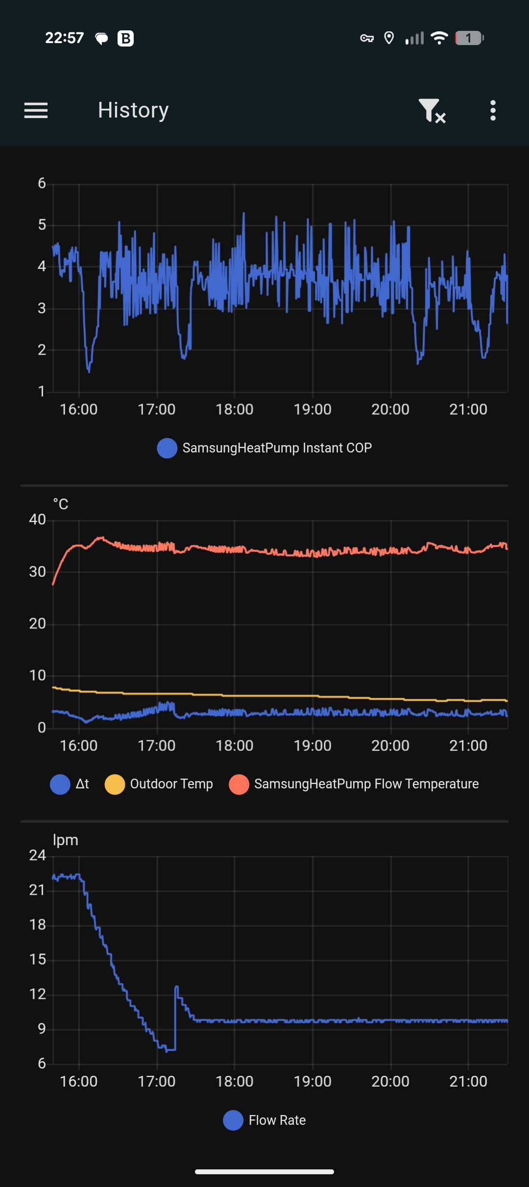
COP is a calculated value by doing (Energy Out/SamsungHeatPump Power). Flow rate is self explanatory I guess.

Ok this is my setup. let’s start with the questions as this is really driving me crazy.

First and foremost, I’m never able to reach dT = 5. I’ve tried balancing multiple times. I either switch off a radiator by restricting the lockshield too much or the dT is not going to be anywhere near 5. Any suggestion on what I may be doing wrong? (I have a thermometer I plug so the flow and return pipe to measure the temp. I make the change to the valve, wait 15 minutes then measure again). On top of this, every time I restrict one radiator, the flow rate drops. At some point it dropped so much that I got error E911. For this setup, what is the suggested flow rate? is there anything wrong with my inverter pump setting (70% and form factor 1) ? It looks like the more I try to get to dt5, the more the flow rate drops and I’ve read it should be around 14lpm!

Second batch of questions are related to the flow temp and how this actually implements the water law. You can see there is a box labelled water law flow temp, that is a value I take from the HP so you can see my calculatio (Samsung Flow Temp) and this box have the same value. Yet the actualk flow temp is always 1 to 2 degrees below that. Is there any particular reason for that? Let’s take today, here in London, 24th November, was mostly 6 to 7 degrees outside during the day. My water law was saying 37 degrees and the heat pump was all the day around 35, moved up a little, down a little, it was actually never stayed on a fixed number (not sure if that’s expected). My house was ok as indoor temp but I wonder why it wasnt giving me the right flow temp. I’ve read something about load compensation that kicks in. I do not know if I have it on my unit but I could not find any reference to it.

Last but not least, I have the feeling my cop is not going particularly well. is very much moving from 4.5 to 1.5 even by staying all the time at the same flow temp with the same outdoor temp. I don’t know guys, I hope you can help me understanding this a little better. Thanks a lot and kudos to who managed to reach the end of this wall of text. I hope to get some answers.

Best regards

Federico

Don’t worry too much about trying to chase dt5. The lockshields are there to make sure you’re getting enough heat to each room, not to limit the flow rate enough to chase a particular dt. I run at a fixed flow rate with a seperate pwm controller for mine, My heatloss is a little higher than yours (around 4.5kW) and run at 13.5lpm. Because I’m running a fixed flow rate it’s only at dt5 when its at -3degrees outside and its lower than this the when it’s warmer outside. I found my gen7 performs better since implementing this.

Error 911 will come up when the flow rate is below 7lpm.

My flow temp is somtimes a degree or two below the target temp, too. It’s just a Samsung thing. Annoying, but not world ending.

Hey Jake, thanks a lot for your reply. I’m not particularly expert on types of installation so not sure what external pwr would be.

I have an upm4 groundforos pump that is controlled by the heat pump. Yesterday I’ve changed the settings so now it’s pushing around 14lpm. I’ll have another round of balancing without looking too much into the dT piece but I have the feeling my COP will suffer. So far I’m not getting anywhere near the theory (MCS data) of 3.65 at 45°. I’m running between 35 and 40 and hitting pretty low numbers (upper 2s, lower 3s) then I started using AI to get some pointers but it’s more the time I wasted than anything.

I’ve now switched from the Nest to the Samsung wired controller as I can control it on home assistant via the Samsung WiFi unit (purchased separately).

Is anyone able to explain like you would do with a child the FSV#2093? I don’t get it apart from the use room temperature (on/off) obviously.

Thanks

You are not the only one who is confused. I suggest you have a read of Struggling to get to grips with my Samsung controller. (It’s a bit of a ramble, but I think we got there in the end.)

Hey Sarah, thanks a lot.

Just by looking at 2093 then, isn’t it bad if the heating stops either by reaching the room temp or the WK required flow temp? It looks like I’ll be giving more ways of stopping to the system while in theory I want it to run all the time. Am I missing anything here?

What is actually happening if the compressor stop but the pump still goes (I think it’s the value 3)?

Thanks a lot for that thread, very helpful

@jakeymd1

This is something I don’t get.

Started the system from cold, after a couple of hours I have the pump running at 56% and flow rate down to 8.6lpm. why is that? I thought it was trying to go for 12/14lpm instead it keeps slowing down. Should I remove more flow restrictions from the lockshields?

Flow temp is supposed to be 36 degrees

It will be slowing down if your dt is less than what you have set as your target dt in #4052. The minimum it will go is 7 lpm, but it often settles higher than this.
It seems like you’re stuck thinking that you should be adjusting the lock shields to control the dt. The lock shields are there to balance your system and ensure heat is being delivered correctly to each radiator. Changes in dt are just a consequence of adjusting the lock shields. Not the reason we do it.
Your heat loss is 4.14kW, so to get 4.14kW with a dt of 5, you need 11.9lpm flow rate. But this is only your design temperature, which is likely around -3 degrees. When it is warmer outside, your flow temperature will reduce because of weather compensation. This means that the output of your radiators reduce. Lets say it’s warmer and you need exactly half the heat loss, 2.07kW. If you maintained the same flow rate, your dt would have to halve, to 2.5, If you wanted to maintain dt5, your flowrate has to halve, to 5.95lpm.

With a flow rate of 8.6lpm and dt of 5, you will still be delivering 2.99kw of heat. So to deliver less heat, the dt also has to drop. To deliver 2.07kW, the dt would have to drop to 3.46.

You can’t have a flow rate of 11.9lpm, a dt of 5 and deliver anything other that 4.14kW of heat. So something has to reduce. Here is the equation: Q(kW) = 0.0698 × Flow(LPM) × ΔT (C).

1 Like

Good questions, Frederico, though I don’t think that there’s a straightforward answer to them.

It sounds like you are thinking about heat pump cycling, and presumably minimising it. As I’m sure you know, cycle frequency is all down to hysteresis – both in the LWT controller, and in the roomstat (though the former depends upon the #209x setting).

Although I don’t think we know exactly how hysteresis is programmed into either algorithm (e.g. 2- or 3-term control), almost always LWT hysteresis will be faster than roomstat hysteresis, because the thermal inertia of the house (or more precisely the room where the roomstat is) is normally much larger than that of the circulating fluid and its containment system (radiators, volumisers/buffer tanks, piping etc.).

So if you are worried about cycling, you should be looking for ways to reduce the effect of LWT hysteresis. One way is to simply increase it (if you have access to #1061 for example); another is to prevent the compressor from stopping even if the LWT setpoint is satisfied (by selecting #2093 = 1). And it is possible to reduce compressor speed (thus heat produced) through selecting Quiet Mode or other (much more advanced) techniques like Frequency Ratio Control). Reducing heat production lengthens the hysteresis time and thus decreases cycling frequency.

Don’t forget that there is a limit to how slow the compressor can run – a controller algorithm shuts it down before damage can occur due to loss of seal/lubrication oil or compressor surge or whatever. Equally there is a limit to maximum speed – the algorithm will constrain it to avoid excessive vibration and casing temperature for example. Not surprisingly, there’s nothing you can do about these limits.

With the #209x settings, Samsung have provided us with flexible options to prioritise roomstat control over LWT control or vice versa, depending upon our individual operating objectives and constraints. For example:

  • Folk who don’t even have a roomstat (or have disconnected it) can control their heat pump simply on LWT, using #209x = 0.
  • Those who choose to operate with a big night-time setback, but want their house to re-warm as fast as possible each day, irrespective of operating cost, might choose #209x = 1. This will allow LWT to keep rising as fast as possible, until the roomstat is satisfied, which would result in a minimised house warming time, but at the cost of a lower CoP due to high LWT.
  • Folk who simply want to minimise their operating costs might choose one of #209x = 2, 3 or 4. This will constrain the LWT (per the WL settings) and thus minimise the operating cost, but would take longer to warm the house if a setback is operated.

The pros and cons of #2093 = 2 or 3 or 4 are more subtle. Keeping the circulating pump on (#2093 = 3) will reduce LWT faster (so reaching the hysteresis temperature quicker and thus increasing the cycling rate), and cost pump energy, but results in a more even heat flow into the house. Switching it off (#209x = 2) results in radiators – and thus the house – cooling more quickly (occupant comfort considerations), but saves pump energy. I’m guessing that this why Samsung provided the compromise (#209x = 4) where you sort of get the best of both worlds through on/off cycling of the pump.

Hopefully none of the above conflicts with Jake’s excellent response above.

I guess I’ve been doing this the wrong was trying to always achieve dt5 by restricting the lockshields at any temp which led to a lot of frustration as I could not. So when the system runs at 35 degrees Vs 40 at -2 of the weather compensation it’s expected to see a lower DT in the region of 2.5/3.

So from.a balancing perspective I just need to be sure the radiator is hot and nothing else. I’ve been measuring DT at the flow and return pipes for days…

Measuring the flow and return isn’t completely wrong. You still want to get a dt of 5, but you need to make sure that the flow temperature is maintained at 40, and the flow rate is 12lpm.

I do it a different way, I use FRVs to set the flow rate to each radiator. It makes balancing far more accurate and now takes a matter of minutes, and not days.

I am not entirely sure what’s wrong with my system and if there’s anything wrong at all. The main issue being I am not able to get to good cop values. I really don’t get it.

Today I went for a full on balancing. Started with all open and gradually started closing the valves. I was able to have an overall dT 5 but the single rads were a bit off. I’ve asked guidance to Gemini but I fear it is just misleading. I think I’m pretty happy right now although the flow rate is around 10lpm

On a separate note, I’ve started using the wired controller from Samsung even if in the cabinet, I’ll just set the temperature to something ridiculous so it won’t switch off the compressor regardless. I’ve read that using an external thermostat is kind of frown upon but considering the way I’m using the wired one, I really don’t understand the issue here.

By using on/off room temperature, at least on my nest 3rd gen) you can still set a target temp for the day and a lower for the night so not really different from the wired one. Also by playing with those settings I still need to understand (thanks @SarahH ), I’m reading it continuously to try and really get it. My installer told me it is better to have it running for as long as possible which means forgo anything than room temp. Setting it high enough you’ll never reach it as it is bad to have the compressor going on and off.

Thoughts?

That is generally the best advise for efficiency. But efficiency isn’t everything. Comfort and running costs ShOuLd be a higher priority.

I would open each lock shield a tiny bit to increase your flowrate a touch. You want to get this up to 12lpm. It might alter dt a little bit, but measuring dt is so imprecise anyway with monitoring.

How are you measuring the COP and what are you getting?

First of all, thanks a lot for your time @jakeymd1 , really appreciated.

For COP I usually do a simple division, energy produced / energy consumed taken from the M5 atom connected to the F1/F2 terminals of the MIM.

I’m using a weather comp curve with points at 40 degrees for -2 outside and 28 flow temp at 20 outside. Slope is 0.55 currently. Even when it runs with flow temp 35, still in the low 3 region.

Not sure what I’m doing wrong

I’m just running some calculations. I see that you’re using a flow temp of 40. Is this the design temperature that the installer used for his calculations? Some of the figures seem off.

Ho Jake, no, the installer used 45 at -2 but 45 degrees is pretty high temp and I was thinking about reducing the curve to hopefully save in energy use. Thing that I don’t think it’s happening.

I’ll show you what happens usually.

I’ll paste my flow rate (lpm). Upon startup we are cruising at around 20ish lpm. Then it goes all the way down to 7 something, then a spike up and then settles around 9.6lpm

It is like this every day.

Hey @jakeymd1 I’ve been reading your explanation over and over as there is something that I’m not getting fully.

As you could see, my flow rate is definitely variable so the system is able to change it. When running at 9.6lpm (like last night), the pump duty was registering 45% so very conservative.

Is it worth keep opening the lockshields to increase the flow considering that the pump has much more room for increasing the flow rate? Am I under using (damaging) the pump somehow?

I assume that if more flow is needed the pump would just increase the speed, is that right?

Apologies, I’ve only just managed to sit down and look at your responses properly.

This is normal for PWM pumps on Samsung. Look at other on heatpumpmonitor.org.
Look at this one from my system when I was running PWM.

This is because it is trying to increase the dt to match your target dt. The longer the water spends in the radiators, the more time it has to lose heat, so the return is cooler, increasing dt.

These are the calculations I was running: https://docs.google.com/spreadsheets/d/1Xu_RyPPkYeMDV0U3NpsJyNVBdhWGJyvY/edit?gid=513654403#gid=513654403

I created this calculator a few months ago but have put your figures in. The problem is, that at a flow temp of 40 degrees, you are not able to heat your house enough, even with an extremely low dt which would give your radiators the highest possible output. Radiator output is based on the mean water temperature, not the flow temperature itself.

Here are is the main useful information: At a flow temp of 40 degrees, and assuming a minimum radiator dt of 2, The temperature you will be able to heat each room up to is in column J, with the radiator dt in column O, and flow rate in column P. Of course, heat will flow through the house, so the temperature will even out. But it’s not reaching the anywhere near 20 degrees, and the DTs have to be extremely low, and flow rates really high.

AT 45 degree flow temperature, things look more normal, but your bathrooms are still very cold.
DTs and Flow rates are where we’d expect them to be.

While lower flow temperatures are more efficient, there’s only so low you can go before you under heating your house. Even at 44 degrees, most of your rooms end up under-heated.

I think you need to start logging and charting all of your data so that you can understand the bigger picture of what is going on. It is almost impossible to tell from a single snapshot in time. Your pump slowing down is not in itself a bad thing. Your controller settings are telling it to do that. If you open the lock shields the duty of the pump will just decrease further, not helping anything.

I stopped using the variable pump speed and now use a fixed flow rate and use FRVs to set the perfect flow rate to each radiator (according to the flow rate on my spreadsheet). https://www.firepowerheating.co.uk/frv

You seem to be changing to adjust things and optimise things without proper understand, and I think that means you are just chasing yourself round in circles.

I Need to read your message over and over and I’ll be probably reading it for a while.

One thing though, I do have multiple data points tracked

But I’m really struggling to understand what is going on and why. I still have my system that is supposed to be delivering 36 degrees (as per calculated weather compensation) and I keep reading 34 and I don’t know why. I’m on the brink of disabling the built in weather compensation, and manipulate the flow temp with my external weather compensation function (that I can change as I please from the phone). When I did the last round of balancing, after we spoke at the beginning, I had a round with the flow temp at 45 and the system was able to handle it. I don’t get why it’s not giving me the temp that I’m supposed to get.

In all fairness I’m really not getting it. It’s not that it just seems to you, it’s actually the reality :frowning:

It’s interesting that you moved in this direction. I’m in a similar position in that my upstairs rads don’t output enough heat at lower flow temps. What impact did switching to these valves have on comfort/efficient/cost?