Thanks, that’s a good site.
If I’ve read it correctly, then the significant conversion factors are:
- dT50 = 1
- dT30 = 0.51
- dT25 = 0.41
- dT20 = 0.3
So if the radiators are broadly equivalent at dT30 then they will be between 20-40% under specified?
Thanks, that’s a good site.
If I’ve read it correctly, then the significant conversion factors are:
So if the radiators are broadly equivalent at dT30 then they will be between 20-40% under specified?
Going all the way back to this comment
I’ve now worked that my radiators will only emit the minimum output heat of 4kW if the run at a flow temp of 45C. At 35C flow temp, I can only emit about 2.1kW. I can supply my workings if that’s helpful.
So my system as is the radiators are never going to achieve a really decent COP. Do I have any options other that increasing the radiator capacity.
That doesn’t sound too bad as you also have the UFH to consider too. I’ve no idea how to calculate how much heat the UFH can dissipate at any given flow temp, but if the radiators can handle half of the heat being produced at 35C flow temp, that sounds reasonable.
I would just ensure all TRV valves are fully open to maximise the system volume the system has to work with.
That means that if a given radiator has a rated output of 1000W at dT50, then at dT of 30 it will output 510W and at dT20 it will be 300W
dT20 could be a room temp of 20C and a flow temp of 40C (technically the radiator temp is the mid point between flow and return, so you may need a flow temp of 42C and return temp of 38C to get ‘40C’)
Fitting fans to radators can increase outout.
Thanks, I’m sure that would help but early conversations with my wife about running power cables to all the radiators have not gone well!
Nor me, but UFH performance seems to be acceptable! All TRvs are open.
Thanks for the clarification and all your advice so far. I seem to working against a couple of things in parallel:
You can’t have separate flow temperatures for each zone without having at least one mixer.
But you could close the UFH zone value for 2 minutes every six minutes for example.
I do have a (manual) mixer value on the UFH manifold just before the UFH pump. I have to admit to be confused about what temp to set on the mixer valve. If it is lower than the flow temp am I not heating the water only to mix it with cold water before it goes through the UFH?
Interesting idea - how does this help?
They are both ways to get water that is hot enough for the radators without overheating the floor. So give a more even downstairs temperature.
Thanks - I’ll have have a think about how to do that,
I have a Samsung AE160RXYDGG Heat pump and work in Energy Industry at an OEM for large industry boilers.
What is important is that if you want to evaluate the performance of a specific piece of equipment you need to draw a box around only that piece of equipment. So if you feed that heat pump a return temperature of 30C due to the way your radiators work or due to the way your floor heating works is irrellevant. The only relevant thing is that it gets 30C return temp.
Same for the water flow: Only the flow in liter/min is relevant. Not why you get that flow, just the fact that you have that flow.
Now if you want to evaluate the performance of your heat pump against what it should be there are 2 numbers people generally look at:
SCOP figures: These are seasonally averaged values and impossible to use for comparison at a single working point. Nice to compare different heat pumps before buying one but that’s it.
COPd figures: These are single testing points. Here is where it becomes interesting!
In my case i could find these in the “Technical data” book that came with the heat pump. The book has a chapter that states "COMMISSION REGULATION (EU) No 813/2013.
Then in the table "Declared capacity for heating at part load at indoor temperature 20°C and outdoor temperature Tj: You find values of the heat supplied by the heat pump under PART load with the value at -7°C matching 100% part load so basically full load.
If you read that regulation it suggests these tests are executed at 30°C return temperature and 35°C leaving temperature. (I guess they let the flow vary to stick to 35/30)
[Regulation - 813/2013 - EN - EUR-Lex](Regulation - 813/2013 - EN - EUR-Lex
The right side of that same value states COP’s the heat pump should achieve at those part load conditions.
So if you want to validate your heat pump against the nominal performance make sure you have:
-Stable operation for some time (30 mins or so should be sufficient for a benchmark)
-Outside temperature close to one of the values is nice, however: if you have 10C and the table only has a value for 1C you could interpolate between the stated values for 12C and 7C to get some feeling of where the performance is compared to nominal.
-Outlet temperature set to 35C, inlet close to 30
-Power consumption measured
That’s it. Everything else is bullshit or if you like meant to facilitate the above requirements.
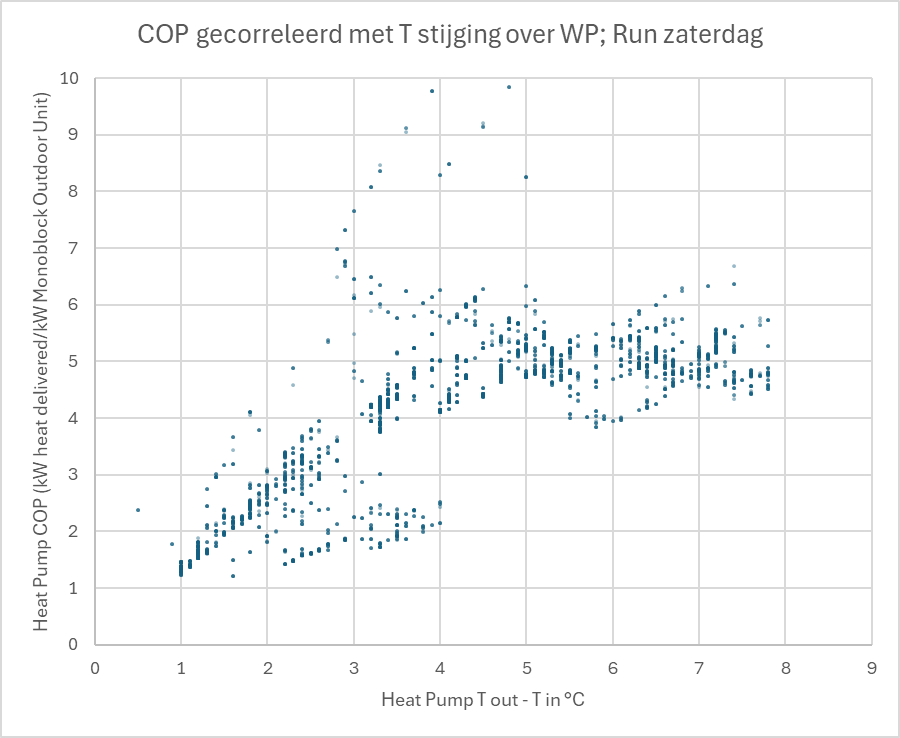
I used a service tool (Samsung Snet 2 Pro) this weekend to analyse the poor performance of my Samsung AE160RXYDGG heat pump.
Did various correlations but this one is the most interesting.
Apparrently below 4 °C something happens in the heat pump that reduces the COP.
Note that I have a fixed flow water pump so no means to influence temperature over the heat pump independent of the heat output.
Most of this data is a run of a few hours where the heat pump was filling my 3000 liter heat storage with a fairly constant output temperature of approxim
ately 47 °C. As time progressed the storage slowly filled and the return temperature of the heat pump slowly increased while the outlet temperature was fairly constant.
Outside temperature remained fairly constant during the day.
Does anyone know what happens in the heat pump that ruins the COP when temperature increase over the HP drops too far?
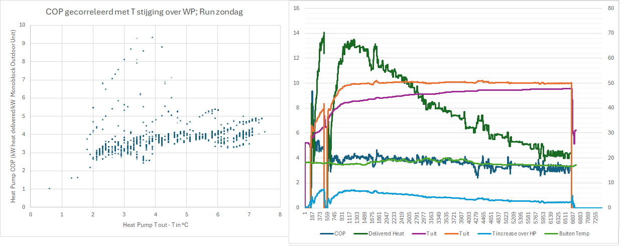
Update: Run of today added…slightly higher setpoint (~50 °C) and slightly lower outside temperature. Run lasts from 14:30 to 20:00 approximately.
Due to less irregularity the curve is more gradual and does not slow the sudden change in slope of the run yesterday.
Very interesting observations, @Martijn_Hinderdael.
What is this, and how does it work? (That is, where exactly does it get the measurements from?)
I 'm not familiar with the AE160RXYDGG, but things I’m thinking:
If you can tell us more about your instrumentation (location, precision, accuracy etc.), other possibilities may come to mind.
Should have been more specific: It was just Samsung Snet and relying on the heat pump’s own instrumentation ![]()
Ah, so where is your Outdoor Unit power data (for the CoP calculation) coming from? Just the remote display? (SNET doesn’t show it.)
One other thought. At constant LWT (which you have, looking at your last graph), an increase in RWT will increase the required R32 condensing pressure = compressor discharge pressure. At constant ambient temperature (which you also have) the suction pressure will be constant, but the pressure ratio will be increasing, which consumes more energy.
(This assumes that the controller compressor energy minimisation algorithm minimises discharge pressure consistent with minimum subcool in the condenser, and maximises suction pressure consistent with minimum superheat in the evaporator.)
I’m beginning to wonder whether your CoP calculation method needs closer examination - those data >> 5 worry me, even if they are only scattered…
Snet shows compressor current and dc voltage. I also have a separate power meter behind the heat pump.
I checked a few times if DC Voltage x compressor current was equal to the output of that meter and it was within a small enough margin to consider that figure useful.
Voltage x Current was actually slightly higher than measured power on my 3 phase meter so I guessed that even fan power is included in the measured compressor current.
It may of course be that this is not the case and part of the current is what we call blind current/blind power in the Netherlands and the calculation somehow gave a fairly similar figure to active power as measured by my power meter. Not sure how that works with DC though.
In any case I think this way of calculating gives a figure usable enough to work with as a comparison between different values in the same log.
On the very high values: If the heat pump ramps up or down the compressor frequency the thermal power is always a bit lagging. So dropping the compressor frequency will lead to a few seconds with a very high COP. That is what you see in the log.
Sarah I see 2 main degrees of freedom in the heat pump when using Snet: Compressor frequency and an actuated valve between condenser and evaporator. (Yes the fans are there too but I ignore these for this moment ![]() )
)
Do you have any info on how this valve is controlled?
With "how’ I mean: What parameter is it set to control (R32 condensate subcooling at condenser outlet? Temperature difference between entering water and leaving R32?)
Hi Martijn,
You are right in saying that the two main process variables are suction and discharge pressure, and the two corresponding controller outputs are compressor motor inverter frequency and Main EEV position. I’ve spent hours studying SNET-Pro2 output spreadsheets, pondering how the controller algorithm works, but without much success, though I can see that inverter frequency correlates quite well against water DT (i.e. LWT-RWT) - a linear fit over the full frequency range 20Hz to 60Hz has an R^2 greater than 0.95.
I suspect (but cannot prove) that the controller algorithm is predominantly using inverter frequency to achieve the desired (minimised) discharge pressure, whilst EEV position is predominantly used to achieve the desired (maximised) suction pressure.
I’m still puzzled by the power monitoring. There are possibly three relevant SNET outputs - Compressor Current1 (supposedly in degC!), OCT (which I believe stands for Outdoor (Unit) Current Transformer, but also shown as degC rather than A), and DC Link1 (i.e. post-rectification of the compressor inverter supply, also degC rather than V). But I have yet to figure out how to derive from any of these the number displayed on the remote monitor. Example: CompCurr = 3.1, OCT = 16, DCLink = 180, Outdoor power consumption (remote display) = 1.5kW. So A.V = 3.1 x 180 = 560W, not 1.5kW. I tried OCT/10 but this doesn’t always work either - see Struggling to get to grips with my Samsung controller post #44 ff. ![]()
Hi Sarah,
I imagine that the valve is to guarantee full condensing before letting the pressure down. If you also let down vapor that just ends up being recompressed by the compressor consuming big amounts of power and ruining the COP. So in my opinion anything other than some form of guaranteeing full condensation of the R32 would be not sensible as a control target for the EEV valve.
Suction pressure is then determined by outside temperature, refrigerant massflow & fan speed. That is: Presuming the heat transfer coefficient on the outside air side is dominant in the heat transfer from outside air to the mostly liquid refrigerant. For fan speed it would be logical to optimize such that the amount of power consumed by compressor and fans together is minimized for whatever outlet condition the compressor is trying to achieve.
For the compressor control algorithm I would have guessed it would strive to achieve a certain pressure but instead there is a column stating a target discharge temperature. Taking a look at some output of Danfoss Coolselect (a program to design refrigeration/heat pump cycles with Danfoss hardware) and then especially the LogPH diagram of the designed thermal cycle I can only imagine that the amount of superheat (and from that: Estimated condensing temperature) correlates fairly well with the temperature difference between compressor in- and outlet.
Measuring temperature instead of condenser pressures is comfortable since it does not require physical contact (and therefore a potential leak source) between sensor and medium.
The compressor current being displayed with unit degree C is in my opinion just a blunt error or something meant to cause confusion. In any case the unit is nonsense for the quantity displayed. Similar for DC Voltage.
This and some other peculiarities (such as the compressor shutting down upon exceeding the water outlet temperature setpoint without much of a timer and without the additional boundary condition of the compressor having achieved minimum RPM for some time) make me feel that much of the programming was done rather quick and dirty.
I have noticed on my display that power consumption does not update frequently. Much less frequently than the values on Snet and the output of my power meter. So I do not take that value too seriously. Again the instantaneous value of Voltage x Current in Snet correlated well with the instantaneous value measured on my external power meter.
Expecting a good correlation between compressor frequency and temperature increase of the water (presuming fixed water flow) or heat output is logical as the compressor has a sort of fixed suction volume per rotation and as long as pressure at the inlet does not vary that much the refrigerant massflow per compressor rotation should be fairly constant.