RS485 and other sensor cabling

I have a try-out of three modbus enabled kWh meters (1x SDM630 and 2x SDM120) and this works just fine. But I still have to do the fuse board installation and move my emoncms from the laptop to a smaller computer (probably a Raspberry Pi 4 with HDD or SSD boot). But I am still a bit uncertain about some RS485 aspects.

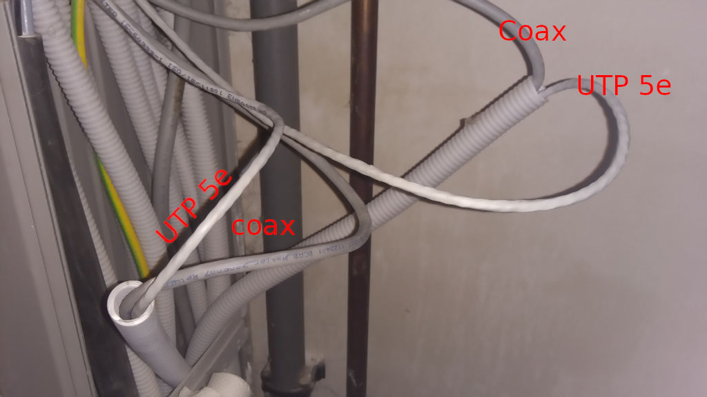
The SDM630 will be some 9,5 meters away from the two SDM120 at another fuse board, where also my Raspberry Pi 4 will be present (to host emoncms). I need “a data cable” of some sort to connect the SDM630 to my setup at the other fuse board. That cable will be running next to power cables (eg. the household + injection to the grid of the solar panels).

About RS485

  1. Official RS-485 cabling exist, but I have read that UTP Cat5E already could do the job. Probably Cat5E S/FTP or Cat6 S/FTP will be better?
  2. I guess a termination resistor will be better? If I use UTP cabling, I probably should use a 150 ohm resistor instead of the RS-485 default of 120 ohm?
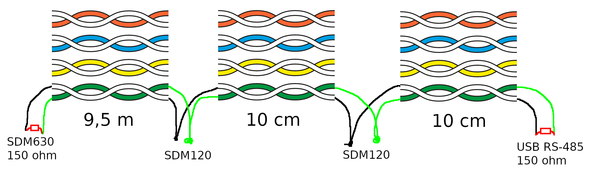
  3. Is such a resistor only necessary at the end (my SDM630 meter in my case) or also at the beginning (my RS-485 USB adapter)? Would my setup then be like:

About the ground wire

My try-out works fine without ground wire, but it has short distances. Still I guess I don’t need the ground wire on the final setup of some 10 metres? But suppose I do:

  1. Can I just use one twisted pair (example orange+orange-white, twisted together on their copper ends) from the UTP cable?
  2. Should it be connected to the ground of my Raspberry Pi? Or to the RS-485 USB adapter (I have 2 without ground and one with)?
  3. The ground section of this webpage also suggest to connect the shield (in case of S/FTP) around the twisted pairs to the ground. Can I connect it to the regular yellow-green ground in my fuse board? Or does it need to be connected to the ground of my Raspberry Pi?

About other sensor cabling

My water meter is close to my SDM630. In the future I would like to use an inductive proximity sensor like in this setup to read my water meter (mine is a LJ18A3-8-Z/BX-5V, with output NPN NO). It has three wires (GND, 5V, GPIO).

  1. Could I take one unused twisted pair from my UTP-cabling, to connect my 5V and GPIO to the Raspberry Pi?
  2. For the ground: can I just use one twisted pair (example yellow+yellow-white, twisted together on their copper ends) from the UTP cable? Should I connect the GND to the ground of the raspberry pi?

That’s not a good beginning. You should separate the data cable from the power by as much as practical, and if there is a need for them to cross, cross at right angles.

That will be the best, but with a relatively short run, the difference should not matter too much. Screened will help if you cannot get far enough away from the power cables.

You need a termination resistor at each end. Whether you supply it or whether it is inside the last device is a matter of checking the data sheets. You must not “double-terminate” the transmission line, i.e. do not fit another if there is one already there. Why do you suggest 150 Ω ? - I think you need to read up on your transmission line theory :wink:. The characteristic impedance of CAT 5 is 100 Ω, and it’s that which you are matching. So 100 Ω, 110 Ω or 120 Ω will be better than 150 Ω.

The ground wire is there to ensure that the common voltage that the data lines are referenced to is the same all the way along the bus, so that the common-mode voltage that the inputs can accept is not exceeded. Distance is not a consideration.

If you do use a screened cable, then if you have a ground wire as well, the screen should be grounded at only one point.
The purpose of the screen is to catch electric fields and prevent them from coupling into the data wires. The purpose of twisting the data wires is so that magnetic fields induce equal and opposite currents into each half-twist, so that they cancel.
You could use the screen as the ground connection between all the devices, but that’s not the best.

I would prefer not use the same cable for the proximity sensor and the RS485 data. If you must use CAT 5/6 cable, I would use one pair for 5 V & GND, and a second pair for output & GND. The GND must necessarily be the Pi’s 0 V, because the Pi measures the output voltage from the sensor with respect to its own 0 V / GND.

If the proximity sensor GPIO output is 5 volts, you may
want to consider 5v to 3.3v Optocoupler. The RP4 GPIO input voltage is 3.3v. Using 5 volts may work for a while, but definitely not a good ideal.

If you use the Optocoupler, the ground between the RaspberryPi and kWh meters will isolated to avoid any ground loops.

Here’s the Modbus.org specifications doc that should answer your question about line termination
as well as the others you posed:

Modbus_over_serial_line_V1_02.pdf (257.9 KB)

With such a short cable length, you may not need terminators. My WattsOns are on a bus that’s
about 8 meters long. They work fine with no termination.

Try it without terminators. If it works without issue, you should be good to go. If not, try adding
the terminators. (If adding them doesn’t help, that means you’ve got issues other than ternimation)

That doc and other Modbus tech docs are available at:
https://www.modbus.org/specs.php

He’s actually spot on. From the spec document: (link in post above this one)

Each line termination must be connected between the two conductors of the balanced line : D0 and D1.
Line termination may be a 150 ohms value ( 0.5 W ) resistor.

I did note that it says may vice shall. AFAICR, everything I’ve read says to use 120 Ω terminators.
Given they’re the folks who maintain the spec…

They mention the use of Cat 5 cable as well.

If 100 Ω cable is being used, then reflections will be reduced if the terminating impedance is closer to the characteristic impedance of the cable, and eliminated (in theory) if there’s an exact match.

True, especially at and above the RF part of the spectrum. Given the sharp rise/fall times
of Ethernet signals, the behavior is very much like that of a UHF signal.
(Cat 5E cable typically has a rating of 350MHz printed on its jacket)

image

As you have said in many posts here on the forum, engineering is very often a compromise.
I figure if the folks that maintain the spec say 150 Ω terminators are OK, that ought to
be fairly safe advice to follow.

Optimal? No.
Does it work? They say it does. :wink:

I nearly added - you don’t want to get into the realms of time domain reflectometry.

From the information I’ve come across, the devices “bridge” the transmission line and may or may not have a built-in (but switchable) termination. I’d still prefer to head towards terminating with a resistance that matches the cable impedance, though on a short length (much less than the 1 km or so that it should work over) it’s not likely to affect performance significantly.

We had a TDR in the radar shop I was assigned to in 1974. I used it to find a break in a fuel quantity
indicator wiring loom on a T-43 Navigator Trainer aircraft. That job would’ve taken a long time, if not
for the TDR. Really saved our bacon. Neat instrument. :smile:

I got to thinking about why I’ve seen so many references to 120 Ω terminators on a Modbus
“network.” I couldn’t quite put my finger on it till now.

Two 100 Ω resistors would load a Modbus pair to 50 Ω. But RS485 line drivers
aren’t rated for loads of less than 54 Ω

Ref:

Choosing the Right Termination

The most popular approach to termination is parallel termination , where you place a resistor across each end of the physical link. Placing it at the end of the line eliminates all reflections, although this approach results in higher power dissipation. Resistive terminators typically have values from 120 to 130 Ω. Although twisted-pair cable impedances can be as low as 100 Ω, a 100 Ω terminating resistor is too low for RS-485 drivers, because two in parallel yield 50 Ω, and RS-485 drivers are not rated for loads below 54 Ω.

Granted that’s not a lot below the spec. But I knew there was something I’d read about it many moons ago. Just couldn’t remember. :grin:

That’s a good find.

Robin Emley lost his electricity supply a while ago. The company gave him a diesel generator while they found the fault in the underground 11 kV cable. They used TDR on that. It took a few days and a few holes dug, he said.

thumbsup

TNX, 'preciate the words.

Unfortunately I don’t have the possibility to separate data and power: they go underneath the floor via “ribbed housing” (I don’t know the correct term). I have two of them I can use. Each of them has a coax (unused) and UTP (in use) inside. I’ll try to use the coax to pull an UTP through (as I don’t think coax will work for modbus communication). My brother still has some UTP around, so it is worth trying. A picture:

Okay, I’ll try without. Thanks for the other explanation! I have some basic knowledge of electricity, but unfortunately not enough to follow the discussion thoroughly. And Robert lost me completely on the “realms of time domain reflectometry:wink:

l first try to work out the reading of the kWh meters, but it is already good to know the hints and tips for my water meter.

We call that “flexible conduit” https://uk.rs-online.com/web/p/conduit/7559023/

I don’t know whether to :laughing: or :cry:

Time domain reflectometry is a way of finding where a fault is in a cable. At the fault, something different happens - either the cable has been crushed, or there’s a break, or there’s a short circuit. An instrument sends a pulse down the cable, and because the electrical properties change at the break, the pulse is reflected back. The instrument measures the time it takes for the pulse to come back. If you know (by testing a good length of cable) how long it takes the pulse to travel a known distance, you can work out where the fault is. It’s very much like radar, but for a cable.

If you have a pulse signal, like the DS18B20 sends, the pulses get reflected at the ends of the cable.
The device reading the data on the one-wire bus can’t tell the difference between the reflected pulses and the pulses transmitted by the DS18B20. The result is corrupted data.

Pull a loop of strong string or cord through as well. Then, being a loop, you can leave the co-ax attached and pull it back in, but keep hold of the ends of the loop and pull the loop around so that it stays in the pipe forever.

Why not give it a try?

If it works, it’ll save you the hassle of pulling a new cable.

My brother came along (who knows much more about electricity) and first we tried to pull the coax through. It was taped to the flexible conduit (thanks for the word @Robert.Wall). The problem was the tape was almost unreachable to remove. We tried to remove as much as possible, but we broke the complete coax cable :-(. I knew my brother has more muscles than I, but I was surprised thát much.

We then first nstalled the SDM630 and after we changed the supply system from “3 phase, 4 wire = 3P4W” to “3 phase, 3 wire = 3P3W”, we seemed to have the correct values on the display.

As the plan for changing the coax for an UTP, I gave the “untouched” coax cable a try to use as my serial link. Well it sometimes work…

$ python3 sdm120-basic.py 
=== General info about address 3 ===
minimalmodbus.Instrument<id=0x7fa3ea32ec40, address=3, mode=rtu, close_port_after_each_call=False, precalculate_read_size=True, clear_buffers_before_each_transaction=True, handle_local_echo=False, debug=False, serial=Serial<id=0x7fa3ea32ecd0, open=True>(port='/dev/ttyUSB_household', baudrate=9600, bytesize=8, parity='N', stopbits=1, timeout=1, xonxoff=False, rtscts=False, dsrdtr=False)>
=== The registers for address 3 ===
  0                  0.0 V     (V for Voltage in volt)
  6   1.2325890064239502 A     (I for Current in ampere)
 12    249.2847900390625 W     (P for Active Power in watt)
 18   293.23907470703125 VA    (S for Apparent power in volt-ampere)
 24  -154.42237854003906 var   (Q for Reactive power in volt-ampere reactive)
 30   0.8353205919265747       (PF for Power Factor)
 70   49.901039123535156 Hz    (f for Frequency in hertz)
 72     7.61799955368042 kWh   (IAE for Import active energy in kilowatt-hour)
 74   14.822999954223633 kWh   (EAE for Export active energy in kilowatt-hour)
 76     4.12999963760376 kvarh (IRE for Import reactive energy in kilovolt-ampere reactive hours)
 78    7.520999908447266 kvarh (ERE for Export reactive energy in kilovolt-ampere reactive hours)
 84   -547.6283569335938 W     (TSP for Total system power demand in watt)
 86   -2452.452392578125 W     (MSP for Maximum total system power demand in watt)
 88                  0.0 W     (ISP for Import system power demand in watt)
 90                  0.0 W     (MIP for Maximum import system power demand in watt)
 92                  0.0 W     (ESP for Export system power demand in watt)
 94                  0.0 W     (MEP for MaximumExport system power demand in watt)
258   1.1122065782546997 A     (ID for current demand in ampere)
264    4.322738170623779 A     (MID for Maximum current demand in ampere)
342    22.44099998474121 kWh   (TAE for Total active energy in kilowatt-hour)
344   11.650999069213867 kvarh (TRE for Total reactive energy in kilovolt-ampere reactive hours)
$ python3 sdm120-basic.py 
=== General info about address 3 ===
minimalmodbus.Instrument<id=0x7efe2c6e7c40, address=3, mode=rtu, close_port_after_each_call=False, precalculate_read_size=True, clear_buffers_before_each_transaction=True, handle_local_echo=False, debug=False, serial=Serial<id=0x7efe2c6e7cd0, open=True>(port='/dev/ttyUSB_household', baudrate=9600, bytesize=8, parity='N', stopbits=1, timeout=1, xonxoff=False, rtscts=False, dsrdtr=False)>
=== The registers for address 3 ===
  0                  0.0 V     (V for Voltage in volt)
  6   1.2292147874832153 A     (I for Current in ampere)
 12   241.64427185058594 W     (P for Active Power in watt)
 18    294.6398010253906 VA    (S for Apparent power in volt-ampere)
 24        -151.65234375 var   (Q for Reactive power in volt-ampere reactive)
 30   0.8573678135871887       (PF for Power Factor)
Traceback (most recent call last):
  File "sdm120-basic.py", line 46, in <module>
    value = instrument.read_float(registers[i], 4, 2)
  File "/usr/local/lib/python3.8/dist-packages/minimalmodbus.py", line 662, in read_float
    return self._generic_command(
  File "/usr/local/lib/python3.8/dist-packages/minimalmodbus.py", line 1170, in _generic_command
    payload_from_slave = self._perform_command(functioncode, payload_to_slave)
  File "/usr/local/lib/python3.8/dist-packages/minimalmodbus.py", line 1240, in _perform_command
    response = self._communicate(request, number_of_bytes_to_read)
  File "/usr/local/lib/python3.8/dist-packages/minimalmodbus.py", line 1406, in _communicate
    raise NoResponseError("No communication with the instrument (no answer)")
minimalmodbus.NoResponseError: No communication with the instrument (no answer)

I checked whether the IAE and EAE matched those on the display and they did. I don’t know why I have 0.0 V. I should check the documentation on this.

About my serial link that doesn’t seem that stable:

  • I could redo my connection, because it was a bit “quick and dirty” and retry.
  • Are there other possibilities? Especially if I wanted to extend my setup with other sensors (eg. water meter). Wi-Fi and ethernet is within reach.

The SDM630_MODBUS documentation shows me that register 0 reads ‘Phase 1 line to neutral volts.’ I guess I will need register 200, 201, 202 and 206 in my three phase, three wire setup. Respectively ‘Line 1 to Line 2 volts’, ‘Line 2 to Line 3 volts’, ‘Line 3 to Line 1 volts’ and ‘Average line to line volts’.

I have redone my connection at one end. And I discovered an error in my emonhub.conf: I had set up two interfacers to use the same device/serial link. I fixed that and at the moment it seems to read everything ok, with a coax cable as serial link. But it is very cloudy today: maybe it will be less stable when a lot of power runs next to the coax cable.

thumbsup

I’m very happy as well :-). I’m still in doubt about the best way to have a water meter sends it sensor data to emoncms, running on a Raspberry Pi 4 in the house (still on my shopping list). It should be something that doesn’t consume much energy. Maybe that a Raspberry Pi Zero is an option?

Anyway: the water meter will only be for my next project. First I have to complete my energy setup (hoping TrystanLea will be able to help me with a working modbus daisy chain that integrates in emonhub :pray: ).