I would like to meter my household, heat pump and solar panels. Our household has a 3 phase connection to the grid. With a single emonTx I would only be able to use an approximate method to estimate the power. Could be ‘good enough’, but I still went for modbus kWh meters, DIN rail mounted. I share my steps: you never know someone wants a similar setup or that someone can improve my steps.
The hardware I use:
- 2x Eastron SDM120M, direct connect, modbus version, one for our heat pump and one for our solar panels.
- 1x Eastron SDM630-Modbus V2, direct connec,t modbus version, for our 3 phase household.
- A computer to read register values. During testing I used a regular laptop with Lubuntu 20.04 LTS. In the future this should be a Raspberry Pi, Odroid C4, … or any other smaller and less energy hungry computer.
- RS485-USB adapter, to be able to read the values through modbus. There are different models, although most have the same chipset (eg. ch341, CP2102, FTDI232).
Some remarks:
- The SDM120 and SDM630 is a series with each 7 models. I use the ‘direct connected’ model: the disadvantage is that the meters must be installed in-line and so they are invasive (in contrast with Current Transformers). Handle with care if you disconnect, rewire and reconnect all the cables!
- DIN rail mounted, so that I can integrate them in my fuse board. So you need some space to put them, which I have.
- Modbus is a data communications protocol to read or store values in a device. You can read every meter on its own communications cable, but it also supports communication to and from multiple devices connected to the same cable. Then you must connect the meters in a daisy-chain fashion, so that you can use one serial link to read the bus. As electrical interface RS-485 is used.
The steps I did
- Connect one SDM120 to the grid (not in the fuse board yet) and read it on a regular Lubuntu 20.04 laptop.
- Make a daisy chain with more kWh meters and read them.
- Configure emonhub and emoncms so that an interfacer can be used to communicate over RS485 with emonhub and store and plot the values in emoncms.
- Mount everything in the fuse board (on my 2DO list).
- Install everything on a much smaller computer than a laptop (on my 2DO list).
The details follow. As you can see on my 2DO list: this is only a try-out and a work in progress. Some basic knowledge of an Ubuntu base operating system, emoncms and emonhub will be necessary.
Preparing computer for modbus reading
Open a terminal (ctrl + alt + t) and execute ls -l /dev/ttyU*. Connect the RS485 USB adapter and use ls -l /dev/ttyU* again: the one that is extra is the USB port assignment. Changes are big it is /dev/ttyUSB0. Problems? The commands dmesg or lsusb provide extra information.
To avoid having to use sudo to execute the script, add the current user to the dialout group, so that that user can read /dev/ttyUSB0.
sudo adduser $USER dialout
The new permission is only effective after logging out and back in again!
Python3 is already installed by default on my setup, but I still have to install minimalmodbus, a Modbus RTU (and Modbus ASCII) implementation for Python. And for that Python module to install, I need pip3.
sudo apt install python3-pip
sudo pip3 install minimalmodbus
SDM120
Documentation:
- SDM120-webpage.
- SDM120-modbus.
- SDM120_Series_Manual (my order also included this on paper).
- SDM120_Series_Datasheet.
Wiring
The official wiring diagram is on the left, on the right two possible wirings to try out. As it is a try out, I just used some plugs and sockets I had lying around. The RS-485 cabling is also with some simple cabling.
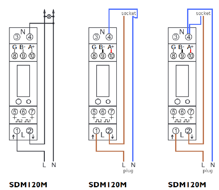
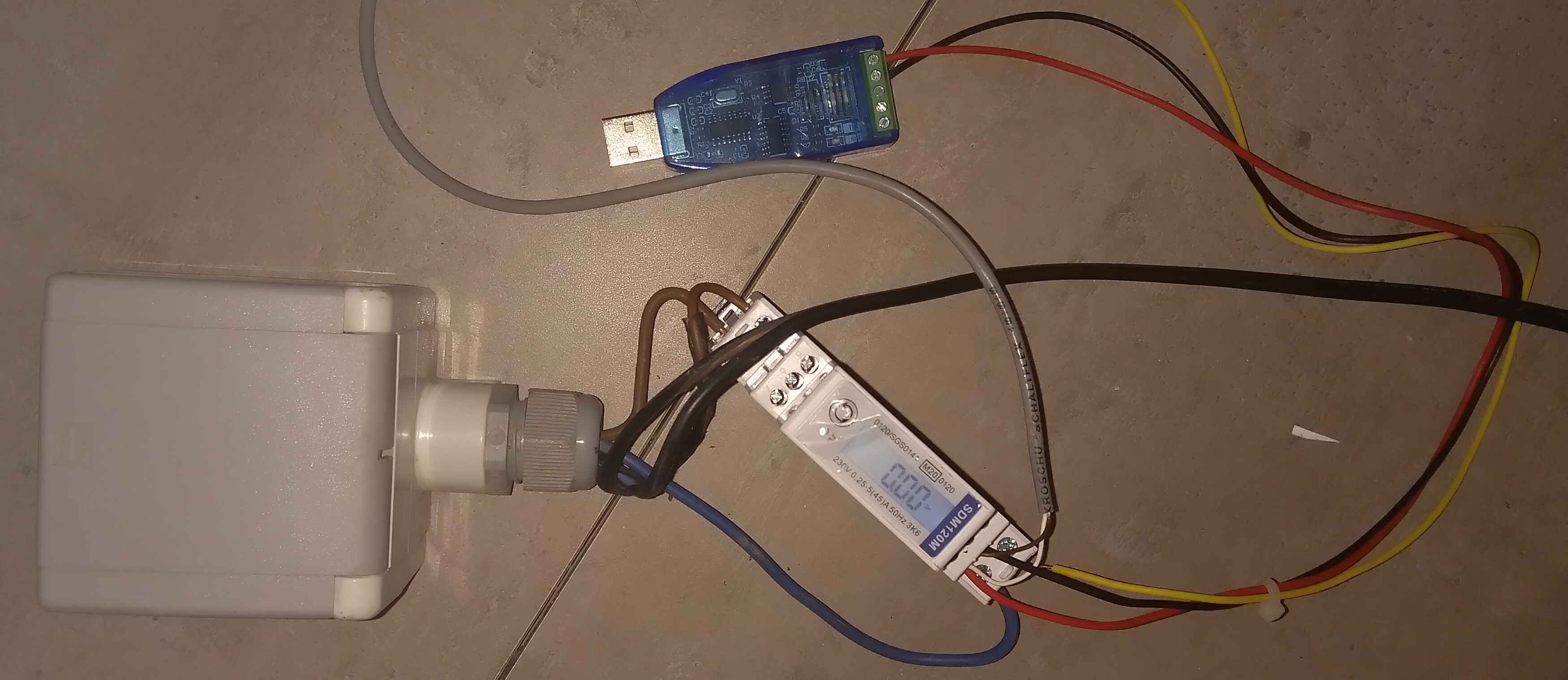
To connect my first SDM120, I used the wiring scheme in the middle. See my picture. The black cable goes to the plug. You can ignore the small gray cable at the moment: that’s already my daisy chain for the next SDM120M. You can also ignore the yellow cable: it’s not connected on any end. I could have use it to connect ground for modbus, but it works fine without it.
Reading values
Connect the plug to the grid: the display will light up and cycle through some values (eg. the voltage on the grid).
Connect the RS485 adapter to the computer. Time to test the reading with the following python script you can execute in a terminal:
#!/usr/bin/env python3
import minimalmodbus

addr = 1
instrument = minimalmodbus.Instrument('/dev/ttyUSB0', addr)  # port name, slave address (in decimal)

instrument.serial.baudrate = 9600         # Baud
instrument.serial.bytesize = 8
instrument.serial.parity   = minimalmodbus.serial.PARITY_NONE
instrument.serial.stopbits = 1
instrument.serial.timeout  = 1          # seconds
instrument.mode = minimalmodbus.MODE_RTU   # rtu or ascii mode

registers = [ 0,  6, 12, 18,    24,  30, 70,   72,   74,     76,     78,   84,   86,  88,    90,   92,   94, 258,  264,  342,    344]
names =     ["V","I","P","S",   "Q","PF","f","IAE","EAE",  "IRE",  "ERE","TSP","MSP","ISP","MIP","ESP","MEP","ID","MID","TAE",  "TRE"]
units =     ["V","A","W","VA","var", "","Hz","kWh","kWh","kvarh","kvarh",  "W",  "W",  "W",  "W",  "W",  "W", "A",  "A","kWh","kvarh"]
info = [
"(V for Voltage in volt)",
"(I for Current in ampere)",
"(P for Active Power in watt)",
"(S for Apparent power in volt-ampere)",
"(Q for Reactive power in volt-ampere reactive)",
"(PF for Power Factor)",
"(f for Frequency in hertz)",
"(IAE for Import active energy in kilowatt-hour)",
"(EAE for Export active energy in kilowatt-hour)",
"(IRE for Import reactive energy in kilovolt-ampere reactive hours)",
"(ERE for Export reactive energy in kilovolt-ampere reactive hours)",
"(TSP for Total system power demand in watt)",
"(MSP for Maximum total system power demand in watt)",
"(ISP for Import system power demand in watt)",
"(MIP for Maximum import system power demand in watt)",
"(ESP for Export system power demand in watt)",
"(MEP for MaximumExport system power demand in watt)",
"(ID for current demand in ampere)",
"(MID for Maximum current demand in ampere)",
"(TAE for Total active energy in kilowatt-hour)",
"(TRE for Total reactive energy in kilovolt-ampere reactive hours)",
]

print ("=== General info about address", addr, "===")
print (instrument)

print ("=== The registers for address", addr, "===")
for i in range(len(registers)):
    value = instrument.read_float(registers[i], 4, 2)
    print (str(registers[i]).rjust(3), str(value).rjust(20), units[i].ljust(5), info[i])

print ("")
An example of an output, with a toaster in the plug.
$ python3 ./sdm120-basic.py
=== General info about address 1 ===
minimalmodbus.Instrument<id=0x7fdb1dcdfdf0, address=1, mode=rtu, close_port_after_each_call=False, precalculate_read_size=True, clear_buffers_before_each_transaction=True, handle_local_echo=False, debug=False, serial=Serial<id=0x7fdb1dcf8370, open=True>(port='/dev/ttyUSB0', baudrate=9600, bytesize=8, parity='N', stopbits=1, timeout=1, xonxoff=False, rtscts=False, dsrdtr=False)>
=== The registers for address 1 ===
  0    242.6999969482422 V     (V for Voltage in volt)
  6    4.927000045776367 A     (I for Current in ampere)
 12   1198.0999755859375 W     (P for Active Power in watt)
 18      1198.1591796875 VA    (S for Apparent power in volt-ampere)
 24                  0.0 var   (Q for Reactive power in volt-ampere reactive)
 30   0.9999989867210388       (PF for Power Factor)
 70   50.040000915527344 Hz    (f for Frequency in hertz)
 72    8.428999900817871 kWh   (IAE for Import active energy in kilowatt-hour)
 74                  0.0 kWh   (EAE for Export active energy in kilowatt-hour)
 76     2.99399995803833 kvarh (IRE for Import reactive energy in kilovolt-ampere reactive hours)
 78   1.0479999780654907 kvarh (ERE for Export reactive energy in kilovolt-ampere reactive hours)
 84    8.363028526306152 W     (TSP for Total system power demand in watt)
 86     1321.80126953125 W     (MSP for Maximum total system power demand in watt)
 88    8.341917037963867 W     (ISP for Import system power demand in watt)
 90     1321.80126953125 W     (MIP for Maximum import system power demand in watt)
 92 0.021111104637384415 W     (ESP for Export system power demand in watt)
 94  0.02305554784834385 W     (MEP for MaximumExport system power demand in watt)
258  0.03573137894272804 A     (ID for current demand in ampere)
264    6.728886127471924 A     (MID for Maximum current demand in ampere)
342    8.428999900817871 kWh   (TAE for Total active energy in kilowatt-hour)
344    4.041999816894531 kvarh (TRE for Total reactive energy in kilovolt-ampere reactive hours)
Problems? Check:
- Do the settings of SDM120 (like baud, …) match those in the script? You can cycle through them with the button on the menu of the meter.
- Is the RS485 adapter available at
/dev/ttyUSB0? Unplug, replug and check dmesg. - Is the A and B cabling for RS485 okay? Even then: some manufacturers unfortunately mix them up, so switch them at one end and retry the script.
Add a SDM120
Wiring
This time I used the other way of wiring (see scheme I posted earlier) with an old distribution plug where I cut the wiring in half.
I daisy chained my extra SDM120 on the left to the existing on the right. Twisted pair cabling and a termination resistor would be better, but at the moment the distance is so short that it should work out just fine.
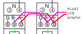
In the picture, the daisy chain to the SDM630 is already attached by using another gray cable, but you can ignore it at the moment.
Reading values
The extra SDM120 also has 1 as default address, but every device on the daisy chain has to have a unique one. The series manual tells me I can keep pressing the button for 3 seconds to enter set-up mode. I changed it to address 2 and kept the other settings.
I can change the address in the already posted script and execute to test. To really test the daisy chain, I wrote the script sdm120-daisy.py below. The differences compared to the first script:
- An extra array
addresses = [1,2]to hold the addresses that I want to read. - An extra loop
for addr in addresses:, where I change the address I want to read withinstrument.address = addr. - A
time.sleep(0.1)so that the script doesn’t try to read the next device too fast otherwise I would get aminimalmodbus.NoResponseError. That’s why I also neededimport timeat the start of the script.
After some trial and error, the value of 0.1 seemed fine. Your setup might need another value.
#!/usr/bin/env python3
import minimalmodbus
import time

addr = 1
instrument = minimalmodbus.Instrument('/dev/ttyUSB0', addr)  # port name, slave address (in decimal)

instrument.serial.baudrate = 9600         # Baud
instrument.serial.bytesize = 8
instrument.serial.parity   = minimalmodbus.serial.PARITY_NONE
instrument.serial.stopbits = 1
instrument.serial.timeout  = 1          # seconds
instrument.mode = minimalmodbus.MODE_RTU   # rtu or ascii mode

addresses = [1,2]
registers = [ 0,  6, 12, 18,    24,  30, 70,   72,   74,     76,     78,   84,   86,  88,    90,   92,   94, 258,  264,  342,    344]
names =     ["V","I","P","S",   "Q","PF","f","IAE","EAE",  "IRE",  "ERE","TSP","MSP","ISP","MIP","ESP","MEP","ID","MID","TAE",  "TRE"]
units =     ["V","A","W","VA","var", "","Hz","kWh","kWh","kvarh","kvarh",  "W",  "W",  "W",  "W",  "W",  "W", "A",  "A","kWh","kvarh"]
info = [
"(V for Voltage in volt)",
"(I for Current in ampere)",
"(P for Active Power in watt)",
"(S for Apparent power in volt-ampere)",
"(Q for Reactive power in volt-ampere reactive)",
"(PF for Power Factor)",
"(f for Frequency in hertz)",
"(IAE for Import active energy in kilowatt-hour)",
"(EAE for Export active energy in kilowatt-hour)",
"(IRE for Import reactive energy in kilovolt-ampere reactive hours)",
"(ERE for Export reactive energy in kilovolt-ampere reactive hours)",
"(TSP for Total system power demand in watt)",
"(MSP for Maximum total system power demand in watt)",
"(ISP for Import system power demand in watt)",
"(MIP for Maximum import system power demand in watt)",
"(ESP for Export system power demand in watt)",
"(MEP for MaximumExport system power demand in watt)",
"(ID for current demand in ampere)",
"(MID for Maximum current demand in ampere)",
"(TAE for Total active energy in kilowatt-hour)",
"(TRE for Total reactive energy in kilovolt-ampere reactive hours)",
]
for addr in addresses:
    instrument.address = addr
    print ("=== General info about address", addr, "===")
    print (instrument)
    print ("=== The registers for address", addr, "===")
    for i in range(len(registers)):
        value = instrument.read_float(registers[i], 4, 2)
        print (str(registers[i]).rjust(3), str(value).rjust(20), units[i].ljust(5), info[i])
    time.sleep(0.1) # To avoid minimalmodbus.NoResponseError
    print ("")
You can avoid the time.sleepby using try-except-else. I have included an alternative (but more complex) script as an attachment.
sdm120_daisychain_alt.txt (2.6 KB)
Add a SDM630
Another type, so other documentation:
- SDM630-webpage.
- SDM630-modbus.
- SDM630_Series_Manual (my order also included this on paper).
- SDM630_Series_Datasheet.
Wiring
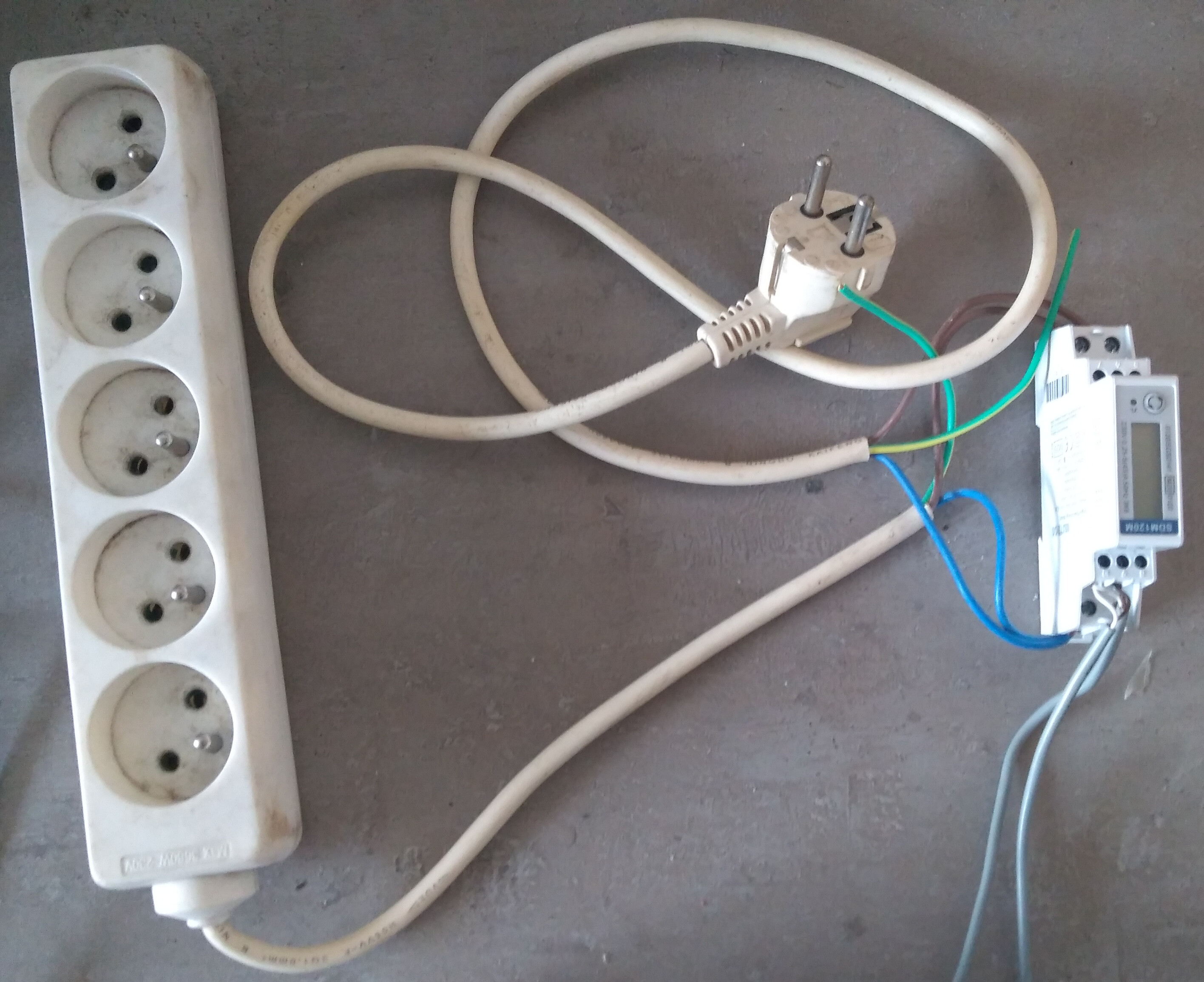
The household is 3 phase, but my regular sockets only have 1 phase, so to test the meter during my try-out I used the ‘single phase two wires’ setup. And I added the SDM630 to the daisy chain. On the bottom I only use brown and blue (yellow and black are not connected). On the top the smaller white cable goes to a plug, so that I can plug it into a regular socket.
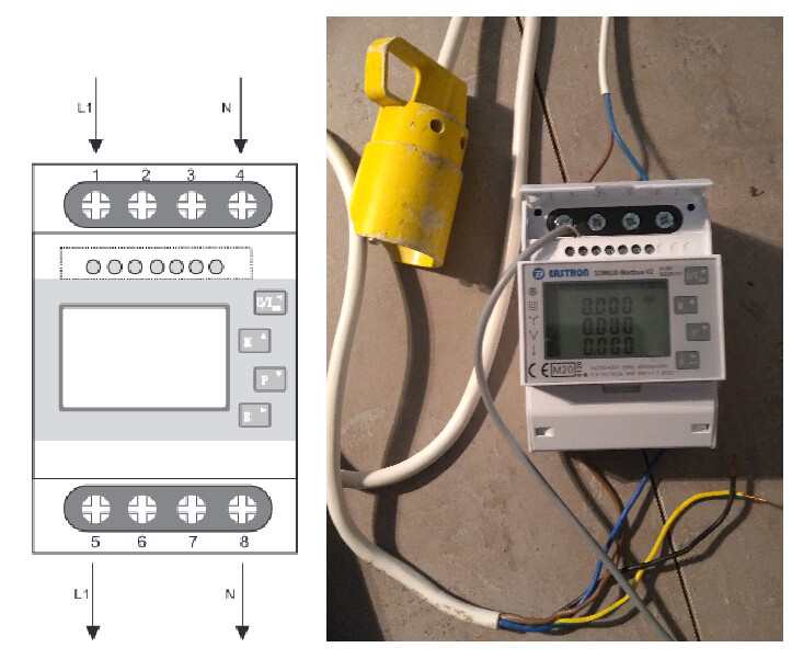
Reading values
Again all addresses need to be unique. The series manual has a chapter ‘Set Up’ and a subchapter ‘RS485 Address’ to help me change the address to 3.
Luckily the registers that are used in the SDM120 are also present in the SDM630. So after changing the address in the code (or add it to the array), I can use the same script to test. You could extend the script to read more registers by reading the SDM630_modbus manual (eg. ‘Phase 2 line to neutral volts’ is at register 2).
emoncms and emonhub
I continue to use my laptop to test, before moving on to a smaller computer and the fuse board. This sections assumes you have emoncms (to read, store and plot the values) and emonhub (sits in between the meters and emonhub) up and running on that laptop. If not, you can follow these steps.
EmonHubMinimalModbusInterfacer.py
Emonhub includes some interfacers by default, eg. “Reading from a SDM120 single-phase meter”. This solution doesn’t allow you to do much settings as eg. choosing registers, applying it to a different modbus meter, … So I’ll use another solution.
Work is being done on a branch “minimalmodbus” to include a EmonHubMinimalModbusInterfacer.py so that also other modbus devices can be read. At the time of writing that new interfacer:
- … allows you to change device (eg.
/dev/ttyUSB0) and baud (eg.9600) inemonhub.conf. - … allows you to change the address of the modbus device in EmonHubMinimalModbusInterfacer.py (eg. 1 or 2 or 3).
- … can read registers that store a float, with functioncode 4 and number_of_registers 2.
- … doesn’t support multiple devices on the same serial link (daisy chaining)… yet, but discussion is going on.
It looks the way to go, so after you have got a default emoncms and emonhub running, we will get the code for EmonHubMinimalModbusInterfacer.py:
cd /opt/openenergymonitor/emonhub
git fetch --all
git checkout minimalmodbus
git pull
sudo service emonhub restart
The emonhub restart on my setup always gives the error below, but it always works on reboot.
Failed to restart emonhub.service: Unit var-log.mount not found.
Add the following to /etc/emonhub/emonhub.conf:
[[SDM120_1]]
    Type = EmonHubMinimalModbusInterfacer
    [[[init_settings]]]
        device = /dev/ttyUSB0
        baud = 9600
    [[[runtimesettings]]]
        pubchannels = ToEmonCMS,
        read_interval = 10
        nodename = heatpump
        registers = 0,6,12,18,30,70,72,74,76
        names = V,I,P,VA,PF,FR,EI,EE,RI
        precision = 2,3,1,1,3,3,3,3,3
Reboot and go to http://localhost/ where you should see the register values on the input page. From there on you can configure your feeds and graphs. Interesting values for a ‘Log to feed’ seem to be the registers ‘Import active energy’ (heat pump), ‘Export active energy’ (PV) and a combination of those (3 phase household on SDM630). In that way the consumption or production in kWh can be measured. Also ‘Active Power’ in watt seems interesting.
Multiple RS-485 adapters
I hope emonhub can soon read other meters on a daisy chain. As I wrote, discussion is going on :-). If you already want to use 3 kWh meters now, you could use 3 RS-485 USB adapters, so each meter has it own serial link. Then you avoid using a daisy chained serial link which EmonHubMinimalModbusInterfacer.py can’t handle at the moment.
What you don’t want is eg. /dev/ttyUSB0 and /dev/ttyUSB1 mixing up after a reboot. Then the monitoring of the heatpump could be seen at the PV (and vice versa). The stackexchange question “How to bind USB device under a static name?” explains how to avoid this. Unfortunately some batches of adapters don’t have a unique idVendor, idProduct or serial. As a workaround I’ll use the usb port they are connected to (see How to distinguish between identical USB-to-serial adapters?). The disadvantage is that I have to always connect an adapter to the same USB port. In short for my own setup (please read the guides to better understand what is going on):
$ udevadm info -a -n /dev/ttyUSB0 | grep -i kernels
    KERNELS=="ttyUSB0"
    KERNELS=="5-1:1.0"
    KERNELS=="5-1"
    KERNELS=="usb5"
    KERNELS=="0000:00:1d.0"
    KERNELS=="pci0000:00"
Having a udev-rule at /etc/udev/rules.d/99-usb-serial.rules. For my situation:
KERNEL=="ttyUSB*", KERNELS=="7-1:1.0", SYMLINK+="ttyUSB_heatpump"
KERNEL=="ttyUSB*", KERNELS=="6-2:1.0", SYMLINK+="ttyUSB_PV"
KERNEL=="ttyUSB*", KERNELS=="6-1:1.0", SYMLINK+="ttyUSB_household"
Reload the udev-rules and do a check:
$ sudo udevadm trigger
$ ls -l /dev/ttyUSB*
$ ls -l /dev/ttyUSB*
crw-rw---- 1 root dialout 188, 0 mei  1 12:11 /dev/ttyUSB0
crw-rw---- 1 root dialout 188, 1 mei  1 12:11 /dev/ttyUSB1
crw-rw---- 1 root dialout 188, 2 mei  1 12:11 /dev/ttyUSB2
lrwxrwxrwx 1 root root         7 mei  1 12:11 /dev/ttyUSB_heatpump -> ttyUSB0
lrwxrwxrwx 1 root root         7 mei  1 12:11 /dev/ttyUSB_household -> ttyUSB2
lrwxrwxrwx 1 root root         7 mei  1 12:11 /dev/ttyUSB_PV -> ttyUSB1
Two things left to do:
- EmonHubMinimalModbusInterfacer.py doesn’t support setting a different modbus address than 1 (yet). So all kWh meters should have 1 as address.
- Edit
/etc/emonhub/emonhub.confaccordingly:
[interfacers]
### From https://community.openenergymonitor.org/t/reading-from-a-sdm120-meter-using-emonhub/16475/90
[[SDM120_1]]
    Type = EmonHubMinimalModbusInterfacer
    [[[init_settings]]]
        device = /dev/ttyUSB_heatpump
        baud = 9600
    [[[runtimesettings]]]
        pubchannels = ToEmonCMS,
        read_interval = 10
        nodename = heatpump
        registers = 0,6,12,18,30,70,72,74,76
        names = V,I,P,VA,PF,FR,EI,EE,RI
        precision = 2,3,1,1,3,3,3,3,3

[[SDM120_2]]
    Type = EmonHubMinimalModbusInterfacer
    [[[init_settings]]]
        device = /dev/ttyUSB_PV
        baud = 9600
    [[[runtimesettings]]]
        pubchannels = ToEmonCMS,
        read_interval = 10
        nodename = pv
        registers = 0,6,12,18,30,70,72,74,76
        names = V,I,P,VA,PF,FR,EI,EE,RI
        precision = 2,3,1,1,3,3,3,3,3

[[SDM630]]
    Type = EmonHubMinimalModbusInterfacer
    [[[init_settings]]]
        device = /dev/ttyUSB_household
        baud = 9600
    [[[runtimesettings]]]
        pubchannels = ToEmonCMS,
        read_interval = 10
        nodename = household
        registers = 0,6,12,18,30,70,72,74,76
        names = V,I,P,VA,PF,FR,EI,EE,RI
        precision = 2,3,1,1,3,3,3,3,3