Radiator Balancing - is there an idiots guide?

I’ve been reading the monster Daikin thread with common references to radiator balancing.

I’m convinced some of my short cycling issues are due to poor balancing.
Very much like Marko says, the house is getting warm but i’m seeing more cycling than I’d hope.

Even though COP hits Vaillant specs!!

My confirmed and recorded heat loss at -3C last winter is around 4kW, so my 5kW Arotherm is not oversized etc.

I’ve messed about in the past and opened some up “a quarter of a turn”.

But in all honesty, I have no idea what i’m doing.
When I ‘google balancing’, it seems to be more about combi setups and DT20.

Ideally we want as fully open as possible, but the ones closer to the heat pump closed just enough to ensure there is enough power to allow to get to the furthest away and index radiator?

But how? Is there an idiots guide to balancing rads for a heat pump setup?

2 Likes

I too am looking for an idiots guide to balancing rads for a heat pump setup.

Firstly, how can one tell that the radiators are not correctly balanced? Is it by looking at how the heat pump responds to certain conditions? Or only by measuring the delta across all the rads?

In principle it’s simple. You just adjust the lock shield valves to get each radiator to be the same temperature, assuming the system has been designed with the right size radiators.

There are 2 main problems; the lock shield valves tend to be non linear, so you find that all the adjustment is when the valve is nearly closed. The second issue is that changing flow in one radiator can affect the flow in other radiators, so it’s a rather tedious iterative procedure.

I’ve just been through this with my newly installed system, took about 3 days to get it about right and I have the advantage of temperature recordings in each room so I can see the effect easily.

1 Like

I gave up. I tried everything. I tried getting a Grundfos balancing pump. It was better, but not great. I spent days and weeks. It was never good enough.

I re-piped the entire system with a manifold. Works like a dream.

On close inspection the original pipework was a total disaster. A large quantity of long runs in 15mm copper, 15mm plastic and additional radiators t-ed of 15mm.

Now I can see and measure that every radiator is getting the same: 4 l/min.

2 Likes

An idiots attempt at radiator balancing…

So using my Testo clamps attached to the flow and return tails of each rad I’ve been around the house and closed down the lockshields on the return side so that I got close to DT5 across the rads. TRV on the flow side all fully open.

The assumption being that you’re losing that 5C of heat from the rads into the room?

It has been 2C to 6C outside today, so some long runs that were ideal to try this.

Is it more complicated that this?

I found that most rads in the house only needed opening less than a quarter turn. Is this normal?

This does seems counterintuitive when you hear about running a ‘fully open system’. :upside_down_face:

1 Like

I’ve gotten as far as setting the lockshield valve to a 1/4 turn on the old and small radiator in the bathroom, which is probably closest to the heat pump, and hoping for the best. I’ve not seen any noticeable difference, and I’ve not measured the delta across it. Maybe I should try doing it properly…

Here is my view on how to balance your radiators, in the beginning you need to make sure that your system is as open as you can, remove all trv heads then run your your heat pump. Try to achieve a delta t of 5-8 degrees on primary flow and return at your desired flow temp, this can be done by regulating your flow rate either by a flow restrictor or pump speed.

Once you have done that move on to your radiators, ideally you need a clip on thermostat for the return from the radiator. Knowing your circuit route will help because you will lose the 5-8 degrees on the latter part of the circuit.

The nearest radiator should have a flow temp as close to the primary then using a thermostat reduce the flow rate on the return lock shield till the temp reduces down to about 5 degrees max differential.Then do that for all the rads.

Remember that you will lose heat on the primary around the circuit so as you come to the radiators furthest away from the primary flow, the flow in to the radiator will be a couple of degrees lower so your return needs to be lower. For example if the radiator closest to the start of the primary flow has a flow temp of 40 then the return should be 35, the radiator furthest away should have a flow temp of 35and a return of 30. That is the correct way because you lose heat from each radiator into the room.

Once you have got this correct you can tweak each rad without affecting the flow rate or delta t. If you have trv’s that are shutting down you are reducing the system volume and that makes it short cycle.

Not everyone’s choice but adding a buffer vessel can also solve short cycling, I can explain that if anyone is interested.

2 Likes

Thanks for the reply Mike.

The other week I tried opening up every rad, but the index rad (landing) and the rad on the top floor were cold.

Is this because there is so little resistance downstairs in the 25mm MLCP, that the flow couldn’t get up to the furthest away rads?

I resolved this by going to back ‘quarter turn’ on them all.

I’ve then chased DT5 on all rads, but not sure that is the right way to go as i’ve throttled most of them down to barely being open?

I’m thinking of trying the whole thing again though, opening all rads up, but then start looking to close down the dining room rads a little first. Try and only close a few rads a little.

As you say, you’re looking to be as open as possible to give you all that volume, but at the same time ensure that all rads get the same flow rate?

Doing it manually with bad valves is a mug’s game.

Buy nice valves. Lockshields that they you KV per part turn from fully shut, such as danfoss RLV. Or presentable TRVs.

Do the math for roughly what the Kv should be. Set them.

Assuming all K22 panel rads you can cheat:

Crank up the heat from cold. Run around and time how long it takes each rad to fill up using a thermal camera.

Tweak against baseline until when you repeat the exercise they all fill at the same rate.

Note the settings. If lockshields close them and count from fully closed each time.

1 Like

So it turns out my installer used very nice IMI lockshield valves, which are “Kv per part turn” as you say @marko

Using the IMI Hytools app on my phone, I put in the size of each rads (height, length, type) and the target flow and return which gave the DT.

From there the app gives you the number of turns to hit the correct flow required for each rad.

I assume this is the technique you are referring to?

Seems to be okay after the first day. I’m getting heat in all the rads and the slow rising of the return temps looks much better than before.

3 Likes

Praise be the installer! Credit where well earned etc. :slight_smile:

Exactly this.

There will be slight differences in practice due to the pressure drops in the pipework. (the app will assume a certain differential pressure at all radiators, but in practice the pressure drops in the pipework will mean that each radiator valves see slightly different differential pressure)

If the pipework is VERY large then these will be negligible and you just balance on the lockshields.

If the pipework is VERY small (e.g. microbore) then these pressure drops may be large or even dominant and balancing is more of a faff.

The “easy” way of correcting for these pressure drops is from “cold start” with a thermal camera. With the radiators at an even temperature; crank the heat on and watch how quickly the radiators “fill” with the hotter water. They should all take the same time to fill if they’re the same style. You can also run around putting fingers on return pipes and guesstimating the moment they become say 5C warmer. Then tweak the baseline Kv from the app up/down to suit.

3 Likes

Inspired by @Zarch experience and diagram I thought I’d revisit my balancing, which was a right faff to start with, and still the playroom is slow to heat up. Hoping to get a bit more efficiency from my over-sized heat pump system.

Below I have sketched out my layout, and annotated some bits, not as nicely I’m afraid. Please don’t laugh, if I knew when the building work was going on, what I know now, I would do it completely differently, but it’s not all my fault. Part was a previous extension when it was a bungalow, that I left as was and the heat pump installer (who is mostly at fault) didn’t even look at most of the internal pipework, and they are now AWOL (and kicked off MCS).

If you have any tips for where I might start please let me know. Most of the pipework is inaccessible, but there are sections of plastic I can swap if it’s worth it, just most of the plastic is hidden under floors. Can the IMI software make suggestions for a good starting point for the existing lockshields even if it won’t be perfect?

1 Like

I’m also trying to balance my radiators, and have started by measuring the temperatures at both ends of each. Some of them have a smaller dT, yet they’re all warm and the rooms are also warm, so not sure what to do next. Any pointers would be appreciated.

image

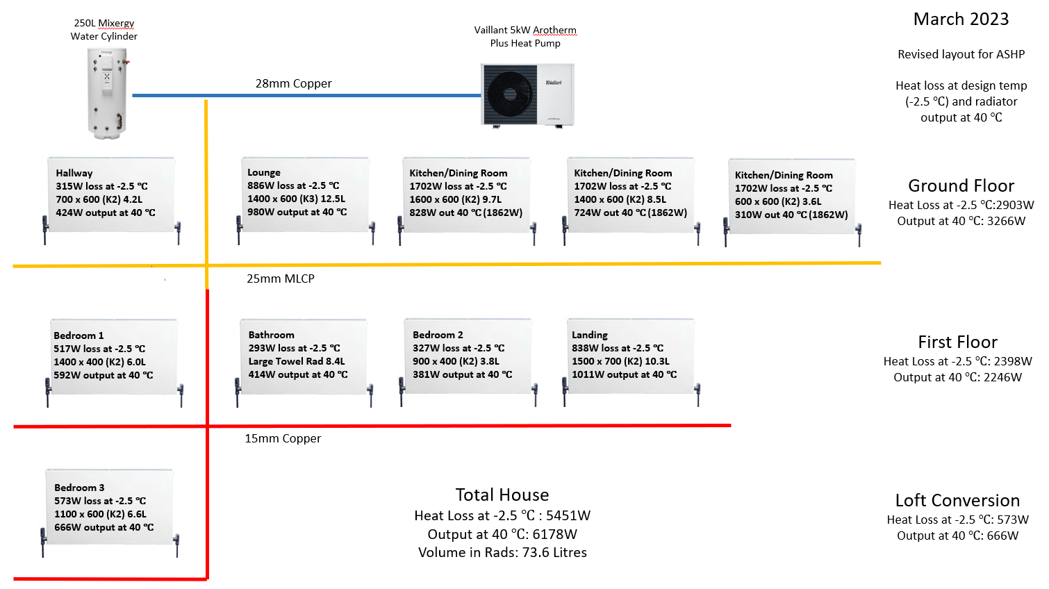
22mm copper has a limit of 6kW at DT5.

So that isn’t a great start on that first leg.
You only lose 1kW on the way, so you’ve then got 5kW heading down 22mm plastic.
22m plastic internally is about 18mm? So that’s only capable of around 4 to 4.5kW?

You might just get away with as you’re losing output along the way. And only 4.5kW at -2C.

How did you end up with an 11kW heat pump for a 4.5kW heat loss!! Save that for the other thread!!

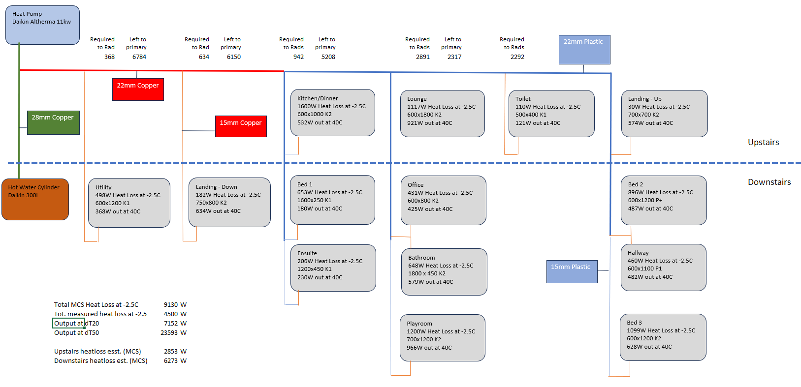
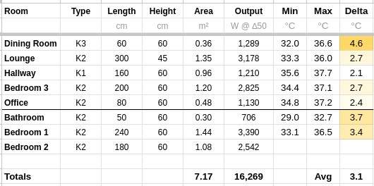
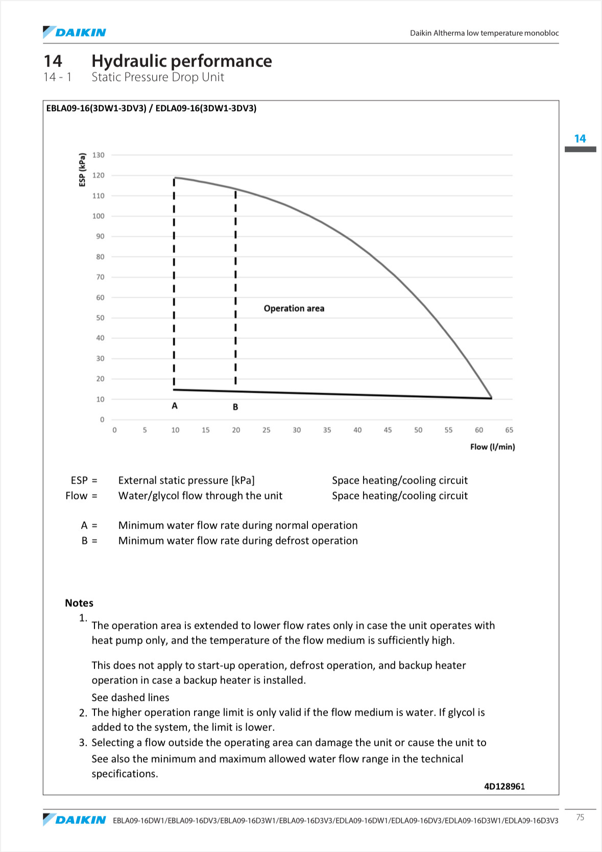
The problem I see and one you might wanna get an expert to look at is, can the pump in the Daikin overcome the resistance to reach the furthest away radiator (the index circuit). This is the individual pipe route with the highest pressure loss. This what you size your pump against.

You could try and balance all you want, but if the pump just can’t physically shove the water down all the narrow pipes, then you’ve got no chance.

Think about how hard it is to blow water down a straw compared to blowing water down a 1 inch pipe.
That’s essential asking the pump to do with narrow pipework, blow it down a straw.

This can be overcome perhaps by fitting an extra pump.
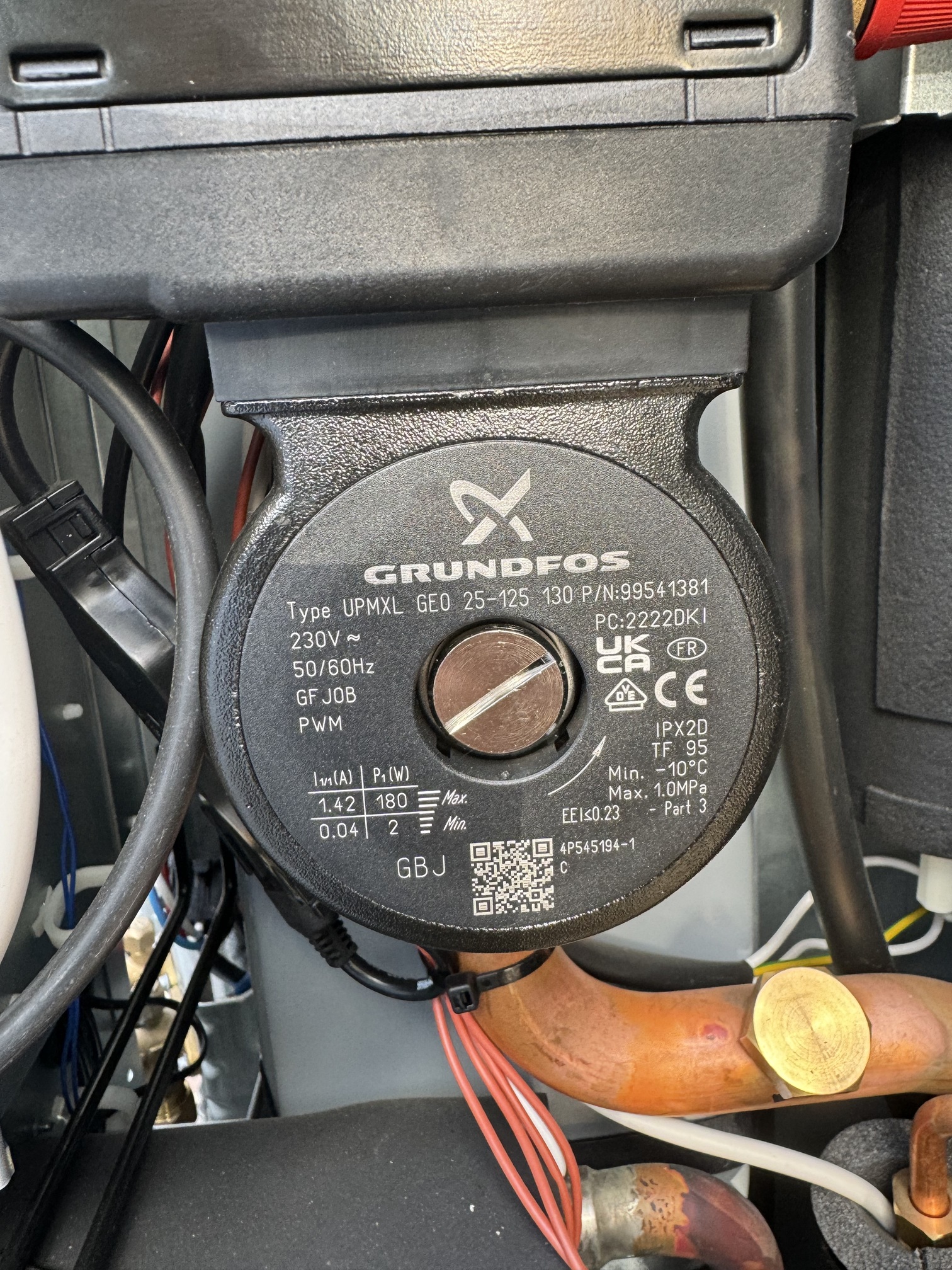
Or perhaps replacing the pump. Does the daikin use an internal or external pump?

But this would all need calculating.

It’s amazing that you know all the layout. That will really help.

You could still try balancing to get that playroom rad warm.
You’d close rads down before that playroom rad, ie, all the other rads.

For example, if I fully open all my rads the ones near the heat pump get warm and the ones furthest away stay cold. I start closing down the rads and the furthest away ones start heating up.

You need to provide enough resistance so that the pump can get to these furthest rads (if the pump can that is)

The IMI app will tell you flow rates required for rad sizes, but it can’t tell you what to do with different lockshields.

Heat Geek do a great vid about the differences in lockshield performance

The chart they create in the vid is here

Does that help at all?

2 Likes

In an ideal world you’d have the output of the rads match the heat loss of the room. This is what I’ve tried to achieve with my rad upgrades. So that if I put the correct calculated flow rate through the rads, all the rooms in the house should be balanced.

But we know this isn’t always the case in a lot of installs. There will be imbalances in heat loss and rad output.

But I still think you start by aiming to get the correct flow through each rad and then you adjust up or down whether you want more or less heat from the rad.

As Heat Geek told me this week, you’re ultimately balancing room temperature.
No own really cares about flow/return or MWT of the rad. The just want warm and balanced rooms.

Obviously from a heat pump point of view, as I’ve found to my cost, you need to ensure there is enough flow going through the rads to ensure you have enough working system volume in the system.

I’d throttled down my rads so bad chasing DT5 across the tails I’d restricted by working volume to barely nothing.

My COP has shot up this last week since opening the rads up. I’ve now given the heat pump more system volume to work with. So excuse the pun, but there is a balance to be had here.

  1. Enough system volume to allow the heat pump to thrive
  2. Rads closed down enough to ensure resistance so that all the rads in the circuit get some heat
  3. The rooms across the whole house are balanced with enough heat being emitted

Obviously, there could be challenges with undersized pipework like @HydroSam has above.

And as Marko days, the underlying pipework adds complexity to the party.

Does that help?

2 Likes

Really interesting Mick @Zarch
It reinforces what I thought, and what I tried to convince OVO of at the time, but they weren’t having any of it, I have a thread on my pump where we could dig in to the heat loss subject if you are interested.

I think the pump is big enough in the monobloc outside, it can draw 100w. The far rad in the playroom does get warm, just not as warm as others.

I can’t adjust the flow rate of the pump, but I can alter the target deltaT. I wonder if I target dT 7 whether that would help. Reading the heat geek link on pipe sizing this suggests I can get more heat output, but I wonder what the compromise/effect will be? Maybe something to try out over the weekend.

1 Like

Raising the dT from “5” to “7” means that for the same radiator output your flow temperature is 1 degC higher (slightly reduced COP) but your flowrates are (N/7) instead of (N/5) - so 70% of what they would have been if targeting dT5.

1 Like

If it’s the same as mine (EDLA 11kW) then here is the spec sheet, which when on space heating at max output, I believe you can take the max flow rate (mine was 24l/m (110kPa) prior to unclogging both strainer/filters and has shot up to 34l/m (95kPa) on space heating afterwards) and get back to the overall static pressure on this graph (please someone correct me if I have misunderstood):

Here is the pump in mine which is the same across 9/11/14/16 units from the datasheet

Here is the data book for the EDLA Daikin Altherma 3M units:

e-b-d-la09-16d-3-v3-w1-eeden20-data-books-english.pdf (3.3 MB)

I should add that with ESPAltherma I’m able to read the water pump signal, so I know when full pump speed signal is generated.

1 Like

@HydroSam

What flow rate are you getting on space heating (not DHW) at max output?

@Stephen_Crown looks to be 22.6l/min in the OEM data, 26l/min when do the DHW cycle. Filters are clean.

I have the older Altherma 2 model. I haven’t checked the pump, I’ll try and do that later.

1 Like