Hey Stephen,
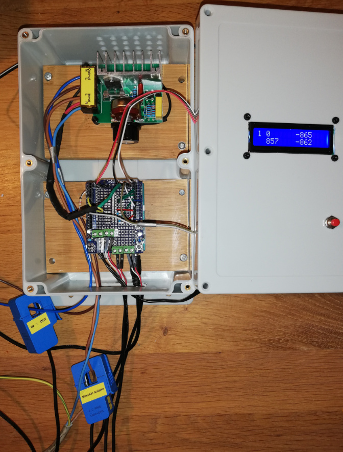
I begin to built your PV router, I am now waiting for the Fortek delivery
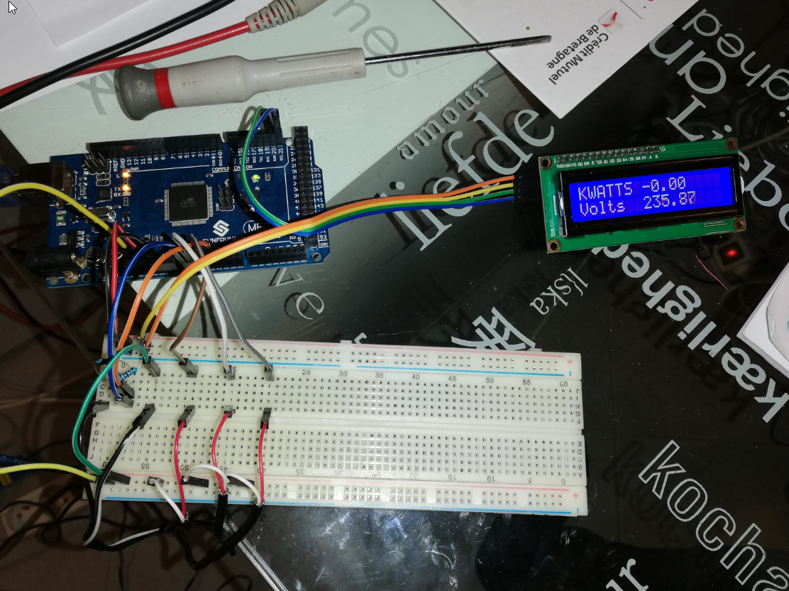
I already reach to measure the voltage, frequency and the 3 power
As my system is :
50Hz - 240V
only 1 SSR 80DA driving the water heater (waiting delivry)
power of the water heater 3000W
PV installed 1300Wc
Could you confirm the setting I have to use… I don’t understand yet all the logic of the program particulary the FRAC parameter
#define FILTERSETTLETIME 5000 // Time (ms) to allow the filters to settle before sending data
#include "EmonLib.h"
EnergyMonitor ct1,ct2,ct3, ct4; // Create instances for each CT channel
#include <Wire.h>
#include <LiquidCrystal_I2C.h>
LiquidCrystal_I2C lcd(0x3f,16,2); // set the LCD address to 0x27 for a 16 chars and 2 line display
#include <PWM.h>
//###### Adjustable settings #######
int upperRANGE = 15; // the range in which it will not search for better output
int lowerRANGE = -15;
int PWM =1 ; //1=enables PWM.h smother output 0=disable
int FRAC =4 ; // fraction of grid Hertz ie 60hz-> 2=1/2 (30hz pwm) 4 =1/4 (15 hz pwm)
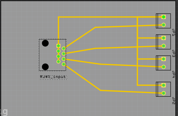
const int CT1 = 1; // divert sensor - Set to 0 to disable if using optional diaplay ( wind)
const int CT2 = 1; // Inverter sensor - Set to 0 to disable
const int CT3 = 1; //grid sensor
const int CT4 = 0; // windgen sensor - Set to 0 to disable disable if using diverter display
int LCD = 1; // 1=enable 0=disable
float element = 3000; //wattage of element for diversion - make bigger then then what you have to decrease buuble search sensitivity
int SSR4 =1; // 1= 4 ssr and disables static, 0= 3 SSR & 1 static ( disable PWM.h)
int ios = 3; /// Number of SSR to control 4 MAX if PWM.h diasble otherwise 3
int pulse = 11; // pin for pulse disable if you cascade on 4 ssr pin 11 does not work if PWM.h enabled
int pulse1 = 9;
int pulse2 = 10;
int pulse3 = 3;
int pulse4 = 11; //enable pulse 4 if you wish 4 cassacding ssr
float DRIFT =1 ; // if you wish to adust hz output
int invstatus = 5; // pin for led display showing overproduction
int type = 1; // 0= casdading - 1 = equal for diverting
int ssr=0; // 0= zerocrossing 1 = phase angle currently only supports one ssr
int AVG=5;
//#### Non - adjustable
int power1=0;
int power2=0;
int power3=0;
float volt=0;
int avg_255 =0;
int avg_ios=0;
int count =0;
int count2 =0;
int count3=0;
int FREQ;
float FREQ_F = 0;
const int aIn = 0;
int positive;
unsigned long period;
unsigned long mark;
float grid = 0; //grid usage
float stepa = 0; //
float stepb = 1;
float stepc = 1;
float prestep =1;
float step1 = 0; //
float step2 = 1;
float step3 = 1;
float prestep1 =1;
float curinvt = 1; //percentage of power uage comparison over or below grid usage
float curelem =1;
float kw = 0;
int curgrid = 0; // current PMW step
int curgrid2 = 0; //current triac step
float invert =100;
float wind = 100;
float diverter =100;
float per = 0;
int stat ;
int stepbu;
float stepa4 = 0;
float stepb4 = 1;
float stepc4 = 1;
float prestep4 =0;
int stepbu4;
int stat4 ;
float curelem4 =1;
int curgrid4 = 0;
int sV;
int full;
int DIVERT = 0;
String value;
int percent = 0;
float TMP;
float DIVS;
typedef struct { int power1, power2, power3, power4, Vrms;} PayloadTX; // create structure - a neat way of packaging data for RF comms
PayloadTX emontx;
boolean settled = false;
void setup()
{
//############### pwm pulse freq for standard pwm #####################
TCCR1B = TCCR1B & B11111000 | B00000101; // for PWM frequency of 30.64 Hz 9 10
//TCCR0B = TCCR0B & B11111000 | B00000101; // for PWM frequency of 61.04 Hz 5 6
TCCR2B = TCCR2B & B11111000 | B00000111; // for PWM frequency of 30.64 Hz 3 11
//#########################
if (PWM ==1){
InitTimersSafe();
}
Serial.begin(115200);
//##############LCD##################################
if (LCD==1) {
lcd.init(); // initialize the lcd
lcd.init();
// Print a message to the LCD.
lcd.backlight();
lcd.setCursor(3,0);
lcd.print("Power Diverter");
lcd.setCursor(2,1);
lcd.print("Stephen krywenko!");
}
//################ detect Hz ###############
boolean st=false; //an indicator to exit the while loop
unsigned long start = millis();
while(st==false) {
while((millis()-start)<200 && analogRead(aIn)>512 );//wait for positive half period to expire
while((millis()-start)<200 && analogRead(aIn)<512 );//wait for negative half period to expire
//Serial.println("zero crossing");
mark = micros();//zero crossing from negative to positive found
while((millis()-start)<200 && analogRead(aIn)>512 );//wait for positive half period to expire
while((millis()-start)<200 && analogRead(aIn)<512 );//wait for negative half period to expire
period = micros()-mark;
FREQ = ( 1000000 / period);
Serial.println(FREQ);
//Serial.println(analogRead(aIn));
st = true;
if (period < 5000){
if (count ==0){
Serial.println("plug in AC adaptor");
if (LCD==1) {
lcd.backlight();
lcd.clear();
lcd.setCursor(0,2);
lcd.print("Check AC Adaptor");
}
count++;
}
st = false;
delay(10000);
start = millis();
}
}
pinMode(pulse, OUTPUT);
if (PWM == 0){
pinMode(pulse1, OUTPUT);
pinMode(pulse2, OUTPUT);
analogWrite(pulse1, 0 );
analogWrite(pulse2, 0 );
}
pinMode(pulse3, OUTPUT);
pinMode(pulse4, OUTPUT);
analogWrite(pulse3, 0 );
analogWrite(pulse4, 0 ); //Enable if you wish to cascade on 4 ssr /disable pulse other below
DIVS= 1 ; // pwm step
// DIVS= ios*2.55 ; // percentage of usable steps
//###################### emontx settings #######################
if (CT1) ct1.current(1, 30.00); // Setup emonTX CT channel (ADC input, calibration)
if (CT2) ct2.current(2, 30.00); // Calibration factor = CT ratio / burden resistance
if (CT3) ct3.current(3, 30.00); // emonTx Shield Calibration factor = (100A / 0.05A) / 33 Ohms
if (CT4) ct1.current(1, 30.00);
if (CT1) ct1.voltage(0, 244, 1.7); // ct.voltageTX(ADC input, calibration, phase_shift) - make sure to select correct calibration for AC-AC adapter http://openenergymonitor.org/emon/modules/emontx/firmware/calibration. Default set for Ideal Power adapter
if (CT2) ct2.voltage(0, 244, 1.7); // 268.97 for the UK adapter, 260 for the Euro and 130 for the US.
if (CT3) ct3.voltage(0, 244, 1.7);
if (CT4) ct1.voltage(0, 244, 1.7);
FREQ = FREQ/FRAC;
count=0;
if (PWM==1){
SetPinFrequency(pulse1, FREQ);
SetPinFrequency(pulse2, FREQ);
}
}
//####### Grid Hertz detection ##################
void Grid_Hz(){
boolean DONE = false;
while(DONE==false)
{
period = 0;
unsigned long start = millis();
while((millis()-start)<200 && analogRead(aIn)>512 );//wait for positive half period to expire
while((millis()-start)<200 && analogRead(aIn)<512 );//wait for negative half period to expire
//Serial.println("zero crossing");
mark = micros();//zero crossing from negative to positive found
while((millis()-start)<200 && analogRead(aIn)>512 );//wait for positive half period to expire
while((millis()-start)<200 && analogRead(aIn)<512 );//wait for negative half period to expire
period = (micros()-mark);
DONE = true;
if (period < 10000){
if (count2 ==0){
Serial.println("Check AC adaptor");
count2++;
}
if (LCD==1) {
lcd.backlight();
lcd.clear();
lcd.setCursor(0,2);
lcd.print("Check AC Adaptor");
}
count=0;
FREQ_F=0;
//##### disable pwm safty measure #######
pwmWrite(pulse1, 0);
pwmWrite(pulse2, 0);
analogWrite(pulse3, 0);
analogWrite(pulse4, 0);
analogWrite(invstatus, 0);
// analogWrite(invstatus2, 0);
analogWrite(pulse, 0);
delay(1000);
DONE = false;
start = millis();
}else
{
count2=0;
FREQ = ( 1000000 / period);
FREQ_F = FREQ_F+ FREQ;
count++;
if (count ==10){
// Serial.print("Frequency = "); Serial.println(FREQ_F/10);
Serial.print("TaskValueSet,2,3,"); Serial.println((FREQ_F/10)*DRIFT); //Frequency
count=0;
FREQ_F=0;
}
}}}
//############## PWM.h setting pulse if used #########
void settingPWM( int _PIN, int _PWM)
{
while(analogRead(aIn)>512);//wait for positive half period to expire
while(analogRead(aIn)<512);//wait for negative half period to expire
delayMicroseconds(period/2);
pwmWrite(_PIN,_PWM );
/*
while(analogRead(aIn)>512);//wait for positive half period to expire
while(analogRead(aIn)<512);//wait for negative half period to expire
//setting the duty to 50% with the highest possible resolution that
//can be applied to the timer (up to 16 bit). 1/2 of 65536 is 32768.
pwmWriteHR(led, 32768);
//Serial.println("High Resolution PWM");
delay(1000);*/
}
void loop()
{
count3++;
if (CT1) {
ct1.calcVI(20,2000); // Calculate all. No.of crossings, time-out
emontx.power1 = ct1.realPower;
diverter = emontx.power1;
power1= (power1+emontx.power1);
if (count3 >= AVG){
power1=(power1/AVG);
Serial.print("TaskValueSet,1,3,"); Serial.println(power1);
}
}
emontx.Vrms = ct1.Vrms*100; // AC Mains rms voltage
if (CT2) {
ct2.calcVI(20,2000); // Calculate all. No.of crossings, time-out
emontx.power2 = ct2.realPower;
invert = emontx.power2;
power2=(power2+emontx.power2);
if (count3 >= AVG){
power2=(power2/AVG);
Serial.print("TaskValueSet,1,2,"); Serial.println(power2);
}
}
if (CT3) {
ct3.calcVI(20,2000); // Calculate all. No.of crossings, time-out
emontx.power3 = ct3.realPower;
grid = emontx.power3;
power3=(power3+emontx.power3);
if (count3 >= AVG){
power3=(power3/AVG);
Serial.print("TaskValueSet,1,1,"); Serial.println(power3);
}
}
if (CT4) {
ct1.calcVI(20,2000); // Calculate all. No.of crossings, time-out
emontx.power1 = ct1.realPower;
wind = emontx.power1;
power1=(power1+emontx.power1);
if (count3 >= AVG){
power1=(power1/AVG);
Serial.print("TaskValueSet,1,3,"); Serial.println(power1);
}
}
volt= (volt+ct1.Vrms);
/*
if (count3 >= AVG){
volt=volt/AVG;
Serial.print("TaskValueSet,1,4,"); Serial.println(volt);
power1=0;
power2=0;
power3=0;
volt=0;
count3=0;
}*/
//######################## Start if bubble Search ###########################
if (invert <0){ // for capture ac adaptor errors is it display consant zero on inverter display -- ct or ac adaptor need to be reversed
invert = 0;
}
if (wind <0){ // for capture ac adaptor errors is it display consant zero on inverter display -- ct or ac adaptor need to be reversed
wind = 0;
}
/////############### old code left in for later modification #################
if (grid != 0 ) {
if (invert >=0) {
step1 = ( grid / invert);
prestep1 = (step2);
step2 = (prestep1 + step1);
if (step2 > 1) {
step2 =1;
}
if (step2 < 0) {
step2 = 0;
}
curinvt = (0 + step2);
curgrid2 = ( 254 * curinvt );
curgrid2 =(254-curgrid2); //inverts the value of curgrid if need be
}
}
//#############################################################
//################# Cascading bubble search ###################
if (CT3){
if ( (grid < lowerRANGE) || (grid > upperRANGE)){
//if (grid !=0) {
//curgrid = 0;
stepc = (grid / element);
prestep = (stepb);
stepb = (prestep + stepc);
if (stepb > 0) {
stepb =0;
}
if (stepb < (0-ios)) {
stepb = (0-ios);
}
curelem = (0 + stepb);
stepbu=curelem;
curelem = (curelem - stepbu);
curgrid = ( 254 * curelem );
curgrid =(0-curgrid); //inverts the value of curgrid if need be
}
//############ static bubble search ###############################
if ( (grid < lowerRANGE) || (grid > upperRANGE)){
//if (grid !=0) {
//curgrid = 0;
stepc4 = (grid / element);
prestep4 = (stepb4);
stepb4 = (prestep4 + stepc4);
if (stepb4 > 1) {
stepb4 =1;
}
if (stepb4 < 0) {
stepb4 = 0;
}
curelem4 = (0 + stepb4);
curgrid4 = ( 255 * curelem4 );
curgrid4 =(255-curgrid4); //inverts the value of curgrid if need be
}
}
//################## determines location of cascading SSR ############
int statc ;
int ivar;
int statb ;
stat = (0-stepbu);
if (curgrid==256){curgrid=0;}
if (stat > (ios-1)) {stat=(ios-1);curgrid=255;full=1;}
if (stat ==0) {ivar = 1;}
else {ivar = 0;}
//################### end of bubble search ######################
//################### Pusle for triac or ssr ###################
if (ssr ==0){
boolean st=false; //an indicator to exit the while loop
unsigned long start = millis(); //millis()-start makes sure it doesnt get stuck in the loop if there is an error.
while(st==false) //the while loop...
{
sV = analogRead(0); //using the voltage waveform
if ((sV < (1024*0.55)) && (sV > (1024*0.45))) st=true; //check its within range
if ((millis()-start)>2000) st = true;
}
DIVERT = curgrid;
//DIVERT=map(DIVERT,0,255,0,120); //delay before pulse
// DIVERT=map(DIVERT,0,120,0,255);
//##############Static Pulse###############//
if (SSR4 ==0){
analogWrite(pulse,curgrid4); // single pulse signal for SSR off arduino board // disable if you want 4 cascading ssr
avg_255=avg_255+curgrid4;
if (count3 >= AVG){
avg_255=avg_255/AVG;
Serial.print("TaskValueSet,2,2,"); Serial.println(avg_255); //curgrid4
}
}
//############################//
//########## Cascading Pulse #######
Grid_Hz();
if ( type == 0){
// Serial.println(" solar Diversion - Cascading");
if (stat != statb) {
statc=(stat+1);
statb=stat;
for(int i=ivar;i < stat; i++){
if ( i == 0){
if (PWM ==0 ){
analogWrite(pulse1, 255 );
}else{
settingPWM(pulse1, 255);
}
}
if ( i == 1){
if (PWM ==0 ){
analogWrite(pulse2, 255 );
}else{
settingPWM(pulse2, 255);
}
analogWrite(pulse2, 255 );
}
if ( i == 2){
analogWrite(pulse3, 255 );
}
if ( i == 3){ //enable for 4th ssr
analogWrite(pulse4, 255 );
}
}
for(int i=statc;i <ios; i++){
if ( i == 0){
if (PWM ==0 ){
analogWrite(pulse1, 0 );
}else{
settingPWM(pulse1, 0);
}
}
if ( i == 1){
if (PWM ==0 ){
analogWrite(pulse2, 0 );
}else{
settingPWM(pulse2, 0);
}
}
if ( i == 2){
analogWrite(pulse3, 0 );
}
if ( i == 3){ //enable for 4th ssr
analogWrite(pulse4, 0 );
}
}
}
if ( stat == 0){
while((millis()-start)<200 && analogRead(aIn)>512 );//wait for positive half period to expire
while((millis()-start)<200 && analogRead(aIn)<512 );//wait for negative half period to expire
//Serial.println("zero crossing");
delayMicroseconds(period/2);
if (PWM ==0 ){
analogWrite(pulse1, DIVERT );
analogWrite(pulse2, 0 );
}else{
settingPWM(pulse1, DIVERT);
settingPWM(pulse2, 0);
}
analogWrite(pulse3, 0 );
if (SSR4 == 1){
analogWrite(pulse4, 0 ); //enable for 4th ssr
}
percent = ((DIVERT)/DIVS);
avg_ios=avg_ios+percent;
if ( count3 >= AVG){
avg_ios= avg_ios/AVG;
Serial.print("TaskValueSet,2,1,"); Serial.println(avg_ios); // percent -- Diverter Percentage
}
}
if ( stat == 1){
while((millis()-start)<200 && analogRead(aIn)>512 );//wait for positive half period to expire
while((millis()-start)<200 && analogRead(aIn)<512 );//wait for negative half period to expire
//Serial.println("zero crossing");
delayMicroseconds(period/2);
if (PWM == 0){
analogWrite(pulse2, DIVERT );
}else{
settingPWM(pulse2, DIVERT);
}
analogWrite(pulse3, 0 );
if (SSR4 == 1){
analogWrite(pulse4, 0 ); //enable for 4th ssr
}
TMP = (DIVERT+255); percent = (TMP/DIVS);
avg_ios=avg_ios+percent;
if ( count3 >= AVG){
avg_ios= avg_ios/AVG;
Serial.print("TaskValueSet,2,1,"); Serial.println(avg_ios); // percent -- Diverter Percentage
}
}
if ( stat == 2){
while((millis()-start)<200 && analogRead(aIn)>512 );//wait for positive half period to expire
while((millis()-start)<200 && analogRead(aIn)<512 );//wait for negative half period to expire
if (PWM == 0) delayMicroseconds(period/2);
//Serial.println("zero crossing");
analogWrite(pulse3, DIVERT );
if (SSR4 == 1){
analogWrite(pulse4, 0 ); //enable for 4th ssr
}
TMP = (DIVERT+510); percent = (TMP/DIVS);
avg_ios=avg_ios+percent;
if ( count3 >= AVG){
avg_ios= avg_ios/AVG;
Serial.print("TaskValueSet,2,1,"); Serial.println(avg_ios); // percent -- Diverter Percentage
}
}
if ( stat == 3){
while((millis()-start)<200 && analogRead(aIn)>512 );//wait for positive half period to expire
while((millis()-start)<200 && analogRead(aIn)<512 );//wait for negative half period to expire
delayMicroseconds(period/2);
//Serial.println("zero crossing");
analogWrite(pulse4, DIVERT ); //enable for 4th ssr
TMP = (DIVERT+765); percent = (TMP/DIVS);
avg_ios=avg_ios+percent;
if ( count3 >= AVG){
avg_ios= avg_ios/AVG;
Serial.print("TaskValueSet,2,1,"); Serial.println(avg_ios); // percent -- Diverter Percentage
}
}
}
//####### Unison pulse #########
if (type == 1){
// Serial.println(" solar Diversion - In Unison");
for(int i=0;i < ios; i++){
DIVERT = curgrid ;
if ( i == 0){
analogWrite(pulse1, DIVERT );
}
if ( i == 1){
analogWrite(pulse2, DIVERT );
}
if ( i == 2){
analogWrite(pulse3, DIVERT );
}
if ( i == 3){
analogWrite(pulse4, DIVERT ); //enable for 4th ssr
}
percent = (DIVERT/DIVS);
avg_ios=avg_ios+percent;
if ( count3 >= AVG){
avg_ios= avg_ios/AVG;
Serial.print("TaskValueSet,2,1,"); Serial.println(avg_ios); // percent -- Diverter Percentage
}
}
}
analogWrite(invstatus, curgrid4); // led display showing overproduction
}
//############################# phase angle #########################
if (ssr==1){
//####### Zerocrossing #######
boolean st=false; //an indicator to exit the while loop
unsigned long start = millis(); //millis()-start makes sure it doesnt get stuck in the loop if there is an error.
while(st==false) //the while loop...
{
sV = analogRead(0); //using the voltage waveform
if ((sV < (1024*0.55)) && (sV > (1024*0.45))) st=true; //check its within range
if ((millis()-start)>2000) st = true;
}
sV=map(curgrid4,0,255,10000,0); //delay before pulse
delayMicroseconds(sV);
analogWrite(pulse,curgrid4);
Serial.print("TaskValueSet,2,2,"); Serial.println(curgrid4);
}
//################# End of PWM controll ############################
//############## LCD ############
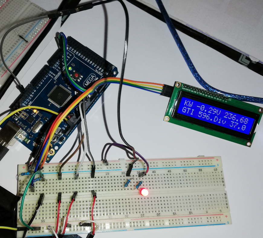
if (LCD==1) {
kw = (grid / 1000) ;
per = ( curgrid / 254);
per = (1 - per);
//per = ( 100 * per);
lcd.backlight();
lcd.clear();
lcd.setCursor(0,0);
lcd.print("KW ");
lcd.print(kw);
lcd.setCursor(8,0);
lcd.print("V ");
lcd.print(ct1.Vrms);
// lcd.print(FREQ);
lcd.setCursor(0,1);
lcd.print("GTI ");
lcd.print(invert);
if (CT1){
lcd.setCursor(8,1);
lcd.print("Div "); //displays Diverter usage
//lcd.print ( "-");
lcd.print (diverter);
}
if (CT4){
lcd.setCursor(0,3);
lcd.print("Wind "); // displays wind inverter output
lcd.print (wind);
}
}
if (count3 >= AVG){
volt=volt/AVG;
Serial.print("TaskValueSet,1,4,"); Serial.println(volt);
power1=0;
power2=0;
power3=0;
volt=0;
count3=0;
avg_255=0;
avg_ios=0;
}
// because millis() returns to zero after 50 days !
if (!settled && millis() > FILTERSETTLETIME) settled = true;
//// ##### if you wish to send data
if (settled)
{
}
}
Thank you
[EDIT - code prefixed and postfixed by a line with 3 backticks - ```
Moderator - RW]