since I upgraded my GTI there no need for the extra functions of my other GTI limiter/diversion hardware
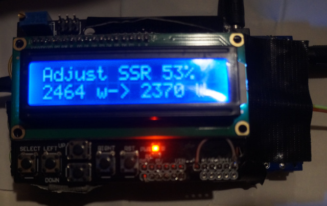
so trimmed it down and made it work based on only a emontx shield , espeasy firmware and wemos R3 uno… My diversion is based on PWM and logic bubble, it is quick and fairly accurate within +/- 10 watts on a 1000 watt diversion element. the smaller the element the more accurate it gets. hence the cascading SSR… as you only have a 100 and 120 possible steps with triac… to get higher accuracy you use multiple cascading diversion at lower wattage. example if I used 2 500 watt diversion then I have +/- 5 watt accuracy compared to the +/- 10 watt accuracy of single 1000 watt diversion. the firmware is set up as 3 cascading and one static. the static is just for grandfathering it into other locations . but you can edit the sketch and have it cascade over all 4 SSRs.
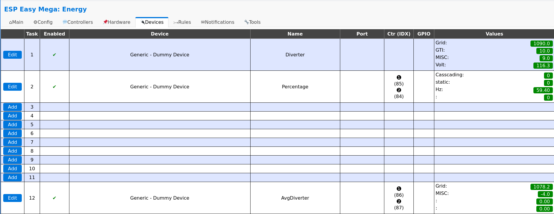
it has wifi connecting transmitting data via Espeasy software and home automation.
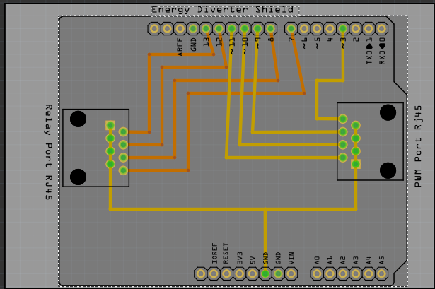
since i am using LCD I disabled CT4 port - the and I use cat5 connection between the UNO and SSR connection block
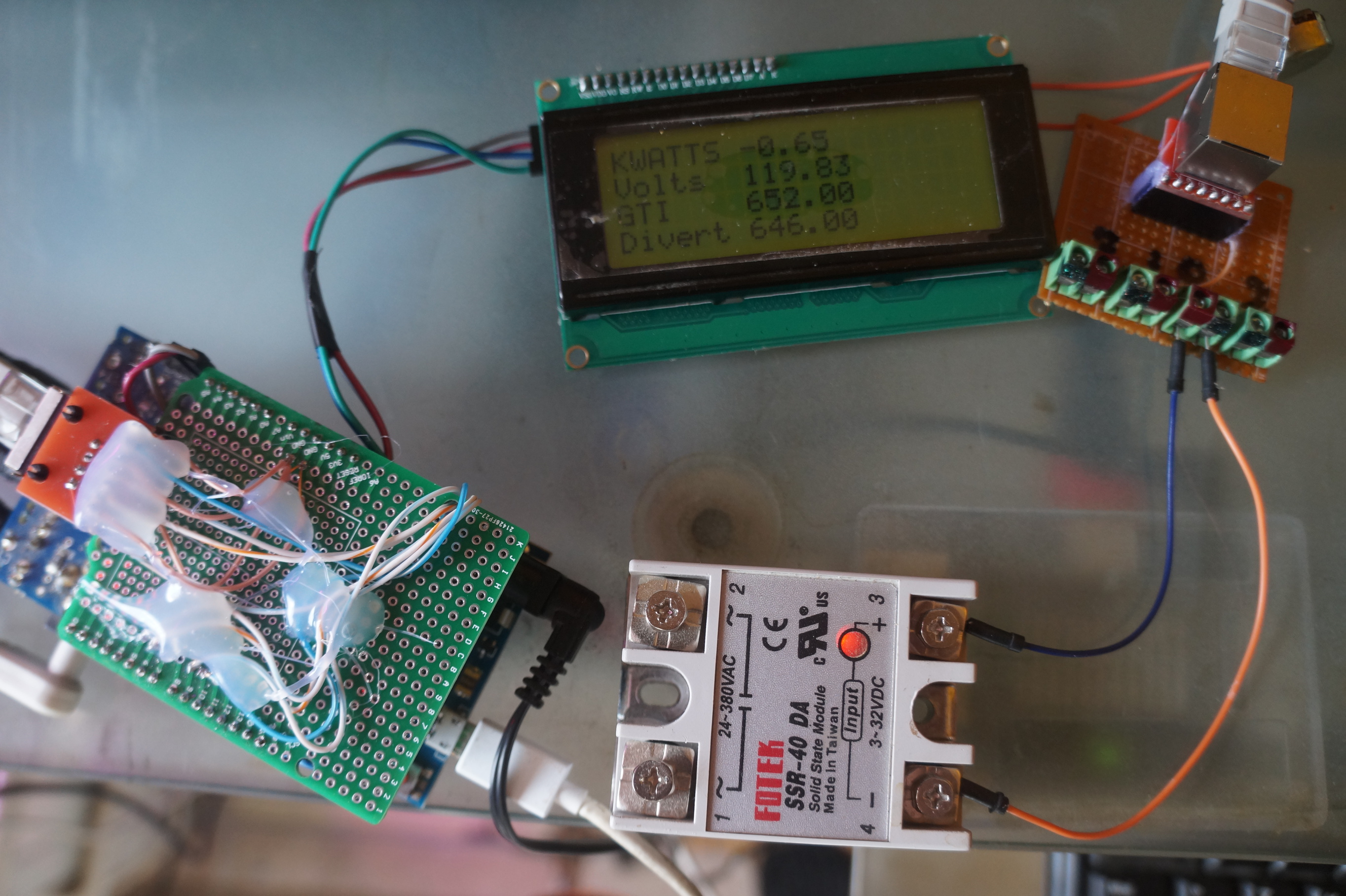
here a picture of it I just have to find a suitable box for it…
firmware:
#define FILTERSETTLETIME 5000 //  Time (ms) to allow the filters to settle before sending data


const int CT1 = 1;                                                      //  divert sensor - Set to 0 to disable
const int CT2 = 1;                                                      // Inverter sensor - Set to 0 to disable
const int CT3 = 1;                                                      //grid sensor
const int CT4 = 0;                                                      // windgen  sensor - Set to 0 to disable  disable if using divert display

float grid = 0;                                                          //grid   usage
float stepa = 0;   //
float stepb = 1;
float stepc = 1;
float prestep =1;
float step1 = 0;   //
float step2 = 1;
float step3 = 1;
float prestep1 =1;
float curinvt = 1; //percentage of power usage comparison over or below grid usage
float curelem =1;
float kw = 0;
int curgrid = 0;                                                      // current  PMW step
int curgrid2 = 0;                                                     //current triac step
float invert =100;
float wind = 100;
float diverter =100;
float element = 5000; //wattage of  element  use in case  no inverter reading or grid tie outside  inverter reading - -

int pulse = 5;       // pin for static pulse  disable if you cascade on 4 ssr
int pulse1 = 9;
int pulse2 = 6;
int pulse3 = 10;
//int pulse4 = 5; enable pulse 4 if you wish 4 cascading ssr

int invstatus = 3;  // pin for led display  showing overproduction
float per = 0;

int stat ;
int stepbu;
int ios = 3;  /// Number of SSR to control in cascading  mode

float stepa4 = 0;   //
float stepb4 = 1;
float stepc4 = 1;
float prestep4 =0; //1
int stepbu4;
int stat4 ;
float curelem4 =1;
int curgrid4 = 0;
int ssr=0; // 0= zerocrossing 1 = phase angle
int sV;
int full;
int type = 0; // 0= casdading -  1 = equal for diverting
int DIVERT = 0;
String value;

#include "EmonLib.h"
EnergyMonitor ct1,ct2,ct3, ct4;   // Create  instances for each CT channel

#include <Wire.h>
#include <LiquidCrystal_I2C.h>
LiquidCrystal_I2C lcd(0x3f,20,4);  // set the LCD address to 0x27 for a 16 chars and 2 line display


typedef struct { int power1, power2, power3, power4, Vrms;} PayloadTX;      // create structure - a neat way of packaging data for RF comms
PayloadTX emontx;

const int LEDpin = 9;                                                   // On-board emonTx LED

boolean settled = false;

void setup()
{
   lcd.init();                      // initialize the lcd
  lcd.init();
  // Print a message to the LCD.
  lcd.backlight();
  lcd.setCursor(3,0);
  lcd.print("GTI Limiter");
  lcd.setCursor(2,1);
  lcd.print("Stephen krywenko!");

  Serial.begin(115200);
  analogWrite(pulse1, 0 );
  analogWrite(pulse2, 0 );
  analogWrite(pulse3, 0 );
  //analogWrite(pulse4, 0 );  //Enable  if you wish to cascade on  4 ssr /disable  pulse other below


  if (CT1) ct1.current(1, 60.600);                                     // Setup emonTX CT channel (ADC input, calibration)
  if (CT2) ct2.current(2, 60.606);                                     // Calibration factor = CT ratio / burden resistance
  if (CT3) ct3.current(3, 60.606);                                     // emonTx Shield Calibration factor = (100A / 0.05A) / 33 Ohms
  if (CT4) ct1.current(1, 60.600);

  if (CT1) ct1.voltage(0, 136.54, 1.7);                                // ct.voltageTX(ADC input, calibration, phase_shift) - make sure to select correct calibration for AC-AC adapter  http://openenergymonitor.org/emon/modules/emontx/firmware/calibration. Default set for Ideal Power adapter
  if (CT2) ct2.voltage(0, 136.54, 1.7);                                // 268.97 for the UK adapter, 260 for the Euro and 130 for the US.
  if (CT3) ct3.voltage(0, 136.54, 1.7);
  if (CT4) ct1.voltage(0, 136.54, 1.7);


}

void loop()
{
  if (CT1) {

    ct1.calcVI(20,2000);                                                  // Calculate all. No.of crossings, time-out
    emontx.power1 = ct1.realPower;
    diverter =  emontx.power1;
    Serial.print("TaskValueSet,1,3,"); Serial.println(emontx.power1);

  }

  emontx.Vrms = ct1.Vrms*100;                                            // AC Mains rms voltage

  if (CT2) {

    ct2.calcVI(20,2000);                                                  // Calculate all. No.of crossings, time-out
    emontx.power2 = ct2.realPower;
    invert = emontx.power2;
    Serial.print("TaskValueSet,1,2,"); Serial.println(emontx.power2);

  }

  if (CT3) {
    ct3.calcVI(20,2000);                                                  // Calculate all. No.of crossings, time-out
    emontx.power3 = ct3.realPower;
    grid = emontx.power3;
    Serial.print("TaskValueSet,1,1,"); Serial.println(emontx.power3);

  }

   if (CT4) {
     ct1.calcVI(20,2000);                                                  // Calculate all. No.of crossings, time-out
    emontx.power1 = ct1.realPower;
    wind = emontx.power1;
    Serial.print("TaskValueSet,1,3,"); Serial.println(emontx.power1);


  }

   Serial.print("TaskValueSet,1,4,"); Serial.println(ct1.Vrms);

 //########################

  if (invert <0){       // for capture ac adapter errors is it display constant zero on inverter display -- ct or ac adapter need to be reversed
    invert = 0;
  }
  if (wind <0){       // for capture ac adapter errors is it display constant zero on inverter display -- ct or ac adapter need to be reversed
    wind = 0;
  }
  //Serial.print(" "); Serial.print(ct1.Vrms);


if (grid != 0 ) {
if (invert >=0) {

  step1 = ( grid / invert);

  prestep1 = (step2);

step2 = (prestep1 + step1);
  if (step2 > 1) {
    step2 =1;
  }
  if (step2 < 0) {
    step2 = 0;
  }
  curinvt = (0  + step2);

  curgrid2 = ( 254 * curinvt  );
  curgrid2 =(254-curgrid2);  //inverts the value of curgrid if need be


}
}

if (CT2){
if (grid !=0) {


  //curgrid = 0;
  stepc = (grid / element);

  prestep = (stepb);

stepb = (prestep + stepc);
  if (stepb > 0) {
    stepb =0;
  }
  if (stepb < (0-ios)) {
    stepb = (0-ios);
  }
  curelem = (0  + stepb);
stepbu=curelem;
curelem = (curelem - stepbu);
  curgrid = ( 254 * curelem  );
  curgrid =(0-curgrid);  //inverts the value of curgrid if need be

}

if (grid !=0) {


  //curgrid = 0;
  stepc4 = (grid / element);

  prestep4 = (stepb4);

stepb4 = (prestep4 + stepc4);
  if (stepb4 > 1) {
    stepb4 =1;
  }
  if (stepb4 < 0) {
    stepb4 = 0;
  }
  curelem4 = (0  + stepb4);


  curgrid4 = ( 255 * curelem4  );
  curgrid4 =(255-curgrid4);  //inverts the value of curgrid if need be

}

}

int statc ;
int ivar;
int statb ;

stat = (0-stepbu);
if (curgrid==256){curgrid=0;}

//#############################//

analogWrite(pulse,curgrid4); // single pulse signal for SSR off arduino board // disable if you want 4 cascading ssr

//############################//


if (stat > (ios-1)) {stat=(ios-1);curgrid=255;full=1;}
if (stat ==0) {ivar = 1;}
else  {ivar = 0;}
  if ( type == 0){
   // Serial.println(" solar Diversion - Cascading");
if (stat != statb) {
  statc=(stat+1);
  statb=stat;
  for(int i=ivar;i < stat; i++){

     ////////pwmController.setChannelPWM(i, 255 << 4);


if ( i == 0){
  analogWrite(pulse1, 255 );
}
if ( i == 1){
  analogWrite(pulse2, 255 );
}
if ( i == 2){
  analogWrite(pulse3, 255 );
}
/*if ( i == 3){                   //enable for 4th ssr
  analogWrite(pulse4, 255 );
}*/
  }

  for(int i=statc;i <ios; i++){

   ///////////  pwmController.setChannelPWM(i, 0 << 4);


if ( i == 0){
  analogWrite(pulse1, 0 );
}
if ( i == 1){
  analogWrite(pulse2, 0 );
}
if ( i == 2){
  analogWrite(pulse3, 0 );
}
 /*if ( i == 3){                  //enable for 4th ssr
  analogWrite(pulse4, 0 );
}*/
     }

     }
      if (ssr==1){
      boolean st=false;                                  //an indicator to exit the while loop

  unsigned long start = millis();    //millis()-start makes sure it doesnt get stuck in the loop if there is an error.

  while(st==false)                                   //the while loop...
  {
    sV = analogRead(0);                    //using the voltage waveform
    if ((sV < (1024*0.55)) && (sV > (1024*0.45))) st=true;  //check its within range
    if ((millis()-start)>2000) st = true;
  }
  sV=map(curgrid,0,255,10000,0);  //delay before pulse
     delayMicroseconds(sV);

    }
     ////////////pwmController.setChannelPWM(stat, curgrid << 4);


     DIVERT = curgrid;


if ( stat == 0){
  analogWrite(pulse1, DIVERT );
  analogWrite(pulse2, 0 );
  analogWrite(pulse3, 0 );
  //analogWrite(pulse4, 0 );                  //enable for 4th ssr
}
if ( stat == 1){
  analogWrite(pulse2, DIVERT );
  analogWrite(pulse3, 0 );
 // analogWrite(pulse4, 0 );                  //enable for 4th ssr
}
if ( stat == 2){
  analogWrite(pulse3, DIVERT );
 // analogWrite(pulse4, 0 );                  //enable for 4th ssr
}
if ( stat == 3){
  //analogWrite(pulse4, DIVERT );                  //enable for 4th ssr
}


  }


  if (type == 1){
   // Serial.println(" solar Diversion -  In Unison");
    for(int i=0;i < ios; i++){
    ///////////// pwmController.setChannelPWM(i, curgrid << 4);

 DIVERT = curgrid ;

if ( i == 0){
  analogWrite(pulse1, DIVERT );
}
if ( i == 1){
  analogWrite(pulse2, DIVERT );
}
if ( i == 2){
  analogWrite(pulse3, DIVERT );
}
/*if ( i == 3){
  analogWrite(pulse4, DIVERT );                  //enable for 4th ssr
}*/

  }
  }


analogWrite(invstatus, curgrid4);  // led display  showing overproduction


kw =  (grid / 1000) ;
per = ( curgrid / 254);
per = (1 - per);
//per = ( 100 * per);
    lcd.backlight();
    lcd.clear();
    lcd.setCursor(0,0);
    lcd.print("KWATTS ");
    lcd.print(kw);
    lcd.setCursor(0,1);
    lcd.print("Volts  ");
    lcd.print(ct1.Vrms);
    lcd.setCursor(0,2);
    lcd.print("GTI    ");
    lcd.print(invert);
    if (CT1){
    lcd.setCursor(0,3);
    lcd.print("Divert ");   //displays current step of triac and ad5206 chip
    //lcd.print ( "-");
    lcd.print (diverter);
    }
    if (CT4){
      lcd.setCursor(0,3);
      lcd.print("Wind   ");   // displays  wind inverter output
      lcd.print (wind);
    }


  // because millis() returns to zero after 50 days !
  if (!settled && millis() > FILTERSETTLETIME) settled = true;

  if (settled)
  {


  }

}
how to flash it to wemos R3 just follow this basic howto it based on espeasy for easy sending of data to various CMS, databases and home automation programs
it has some remant code from the base emontx sketch it just needs a little more clean up.
okay good luck have fun