So now for 50Hz what will happen? as it is not a multiple of 50Hz, it risk to create power instability?
I now have to wait receiving my SSR to test it with power…
Thank you Stephen
if you set it at 2 it should automatically use 25hz as first it detects the grids hz and then divides it … so in your case it should see that it is 50hz and then divide by 2 to get 25hz… but you can play with what ever setting you want and find what works best in your part of the world :). if it not a divisible of 50 hz all that happens is you get a a higher undulation or develop holes within the step pattern. but since at ever cycle it resets the pwm to 50% pass the zero crossing… you can also adjust that if you like until you get the smoothest output possible when using pwm.h
you can edit this line
delayMicroseconds(period/2);
found in here
void settingPWM( int _PIN, int _PWM)
{


  while(analogRead(aIn)>512);//wait for positive half period to expire
  while(analogRead(aIn)<512);//wait for negative half period to expire
  delayMicroseconds(period/2);

   pwmWrite(_PIN,_PWM );
Are you certain that your electricity meter measures kVAh? My research indicates that your supply is rated in kVA, but you pay for energy measured in kWh.
Oups… yes you are true, on my counter the direct reading is in VA but on the bill, it is in kWh. That mean, my first PV router was maybe working, I can make a test to check. Nevertheless I will continue building the new one as I am learning a lot… And nothing else to do at home up to 11th may :visage fou:
Remember, VA is apparent power (puissance apparente) and is the average voltage multiplied by the average current. Active power (puissance active) is the average value of (instantaneous voltage multiplied by instantaneous current). The energy you pay for is the active power integrated over time.
You might be able to change the display to show kW, kWh, VA, VAh, and possibly VAr.
I guess most consumers are more interested in making sure the lights don’t go out due to a contractual trip, so it makes sense to display the kVA stuff (current and daily maximum) by default. I could’t easily determine what other display options are available but it seems you only have to press the + and - buttons to scroll through them all.
That’s just about what I found out too. But like you, I expected to find a (promised) list of display options - I guess it’s in the video I wasn’t prepared to struggle through - my French is not nearly as good as David’s English.
And apparent power (kVA) doesn’t have a direction. I’m curious as to what the instantaneous kVA reading shows when you’re exporting bulk power (no diverter in place). Unless they do something clever, it may well just show apparent power passing through the meter in either direction. They could possibly “filter” the reading, based on the current real power (kW) direction, which the meter obviously knows for billing purposes.
Energy diverters don’t typically make Irms go to 0, so you wouldn’t expect your kVA reading to go to zero even if it was working correctly.
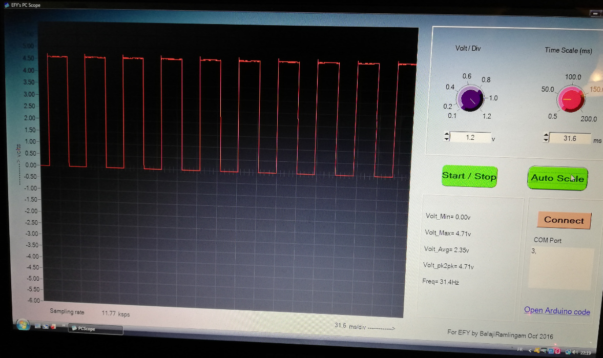
It work correctly when not using PWM.h, the signal come from 100% time at 5V to 0% time (but at 30Hz) so the regulation of power is unstable espessially at low load.
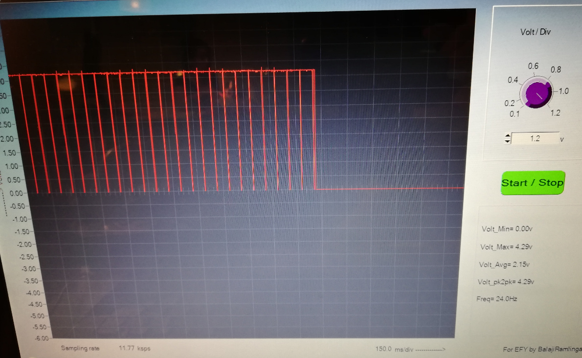
When I try to enable PWM.h (FRAC 2) so working at 25Hz it come from 100% time 5V to 90% time and then brutally fall at 0V full time
Hello Stephen,
Yes !! all is working at 25Hz - FRAC 2 with these setting’s :
//###### Adjustable settings #######
int upperRANGE = 100; // the range in which it will not search for better output
int lowerRANGE = -100;
int PWM =1 ; //1=enables PWM.h smother output 0=disable
int FRAC =2 ; // fraction of grid Hertz ie 50hz-> 2=1/2 (25hz pwm) 4 =1/4 (12.5 hz pwm)
const int CT1 = 1; // divert sensor - Set to 0 to disable if using optional diaplay ( wind)
const int CT2 = 1; // Inverter sensor - Set to 0 to disable
const int CT3 = 1; //grid sensor
const int CT4 = 0; // windgen sensor - Set to 0 to disable disable if using diverter display
int LCD = 1; // 1=enable 0=disable
float element = 3000; //wattage of element for diversion - make bigger then then what you have to decrease buuble search sensitivity
int SSR4 =4; // 1= 4 ssr and disables static, 0= 3 SSR & 1 static ( disable PWM.h)
int ios = 1; /// Number of SSR to control 4 MAX if PWM.h diasble otherwise 3
int pulse = 11; // pin for pulse disable if you cascade on 4 ssr pin 11 does not work if PWM.h enabled
int pulse1 = 9; // pin to use to divert on 1 SSR
int pulse2 = 10;
int pulse3 = 3;
int pulse4 = 11; //enable pulse 4 if you wish 4 cassacding ssr
float DRIFT =1 ; // if you wish to adust hz output
int invstatus = 5; // pin for led display showing overproduction
int type = 0; // 0= casdading - 1 = equal for diverting
int ssr=0; // 0= zerocrossing 1 = phase angle currently only supports one ssr
int AVG=5;
I reach to regulate the power correctly.
As this energy go to the water tank and the need of the family is about 5kWh; do you think possible to add an energy counter, to know how many energy it is necessarry to addition during the night.
ex:
Familly necessary power = 5kWh
Diverted power today = 2.0kWh
Necessary power to be injected during night = 3kWh
Water tank power = 3000W
So supply at full load the resistance during 1h
And once a week supply the résistance during 3h to be sure to have no legionelose
I would like to do it but I have clearely not the level…
I know It is possible to use emonlib to get the energy counter
i found for me that the moc3043 will work better as the moc3041 chops off the the lower steps. and generally only works between ~80 -255 step if you used a moc3043 you get the full range from 1- 255 complete steps
but glad you got it working for you…
if you find it a bit too quick to jump just increase the element size it make it a bit slower to find the correct step but it maintain a better a tighter line to the zeroed grid
by the way how many SSR/triac are you controlling since you have it set to 4 if you only have the one then just set it to one… or two if you plan to add more…
do you think possible to add an energy counter,
sure you could add it to sketch if you like… or buy the wemos uno/wifi card and you can send the data to your prefered visualization database emocms, influxdb… etc
here link how to set that up
and if you used the home automation software you can have it trigger the timing of the events you want.
hi there David
here a simple code adjustment if you like
it will allow for you to use home automation software such as domioticz to be scheduled to turn on your hot water tank at specific times…
– I never tested it but it should work for you - it should over ride SSR 1 data if it has a value over 10
all you have to do is buy a wemos uno/wifi and connect one of it gpio to pin from the esp and connect it to the uno pin 6.
then setup espeasy to send a pwm to that gpio… according to what ever you want from your home automation software…
and just mentioning I would put the temp sensor on the espeasy as I find that it slows down the uno code too much and creates issues . then have it turn off the SSR 1 when the 70C temperature is reached… would do that in the rules of espeasy firmware that overrides the home automation software call to heat the tank – or if you do not want to use software controlled thermostat you can add another mechanical thermostat . but can be tricky to fine place to place it …
edit : I could not edit the above code. (just sat there spinning )… but this will work
in your web browser this should work to manually adjust pwm
http://your_ip/control?cmd=pwm,12,0 to turn off ( 0 - 1023)
http://your_ip/control?cmd=pwm,12,1023 100% on
I used gpio 12 on the espeasy and directed it to pin 6 on the uno on a wemos uno/wifi board – fully controllable by home automation software … just use gpio 04 for your dallas temp sensor for temperature control
Forgot to mention under hardware in espeasy set GPIO output low otherwise it will start SSR at full at boot which would be a bit dangerous as by default espeasy power up with power on pin which would set your SSR to full …
Hey Stephen,
Ok I am waiting for MOC3043 but 3041 seem to be working quite well, maybe unstable around 150W but it is realy not so bad. The final setting I use are here
//###### Adjustable settings #######
int upperRANGE = 100; // the range in which it will not search for better output
int lowerRANGE = -100;
int PWM =1 ; //1=enables PWM.h smother output 0=disable
int FRAC =4 ; // fraction of grid Hertz ie 50hz-> 2=1/2 (25hz pwm) 4 =1/4 (12.5 hz pwm)
const int CT1 = 1; // divert sensor - Set to 0 to disable if using optional diaplay ( wind)
const int CT2 = 1; // Inverter sensor - Set to 0 to disable
const int CT3 = 1; //grid sensor
const int CT4 = 0; // windgen sensor - Set to 0 to disable disable if using diverter display
int LCD = 1; // 1=enable 0=disable
float element = 50000; //wattage of element for diversion - make bigger then then what you have to decrease buuble search sensitivity
int SSR4 =1; // 1= 4 ssr and disables static, 0= 3 SSR & 1 static ( disable PWM.h)
int ios = 1; /// Number of SSR to control 4 MAX if PWM.h diasble otherwise 3
int pulse = 11; // pin for pulse disable if you cascade on 4 ssr pin 11 does not work if PWM.h enabled
int pulse1 = 9; // pin to use to divert on 1 SSR
int pulse2 = 10;
int pulse3 = 3;
int pulse4 = 11; //enable pulse 4 if you wish 4 cassacding ssr
float DRIFT =1 ; // if you wish to adust hz output
int invstatus = 5; // pin for led display showing overproduction
int type = 0; // 0= casdading - 1 = equal for diverting
int ssr=0; // 0= zerocrossing 1 = phase angle currently only supports one ssr
int AVG=5;
I slow down the regulation by increasing a lot “element” to 50000, chose FRAC = 4 and increase the range to +100/-100… it is unity W if I well understand.
To automatise the system I connect the MOC/TRIAC in parallel of the night activation, as we take the shower during the morning the sun can heat the water during day and finish to heat water during night.
How do you know if it is necessary to adjust the drift output, I see in you program it is adjust to 1.015?
And how is it possible to have the % of activation of SSR on LCD screen, I try with avg_ios but it is not working?
Yesterday I collect my first 3 kWh in the water… very happy
So the system is fully operational for me.
Unfortunatly the next days are rainy, so no more test for me.
well the drift I just compared the average hz from a outlet sensor the outlet sensor said it was around 60.2 hz and the Arduino was averaging it out a 59.3 so i just adjusted the drift so it matched my outlet sensor … it nothing important just mainly cosmetic.
50000 is big increase for 3000 element 10000 is about as high as I ever went but generally maybe around 1.5 X to 3 X my element size. unless I wanted very responsive as in wind gen as they are over the place for power output…
-100/100 that the upper and lower limit for trying to find a better step… for me i would calculate that roughly as actual 3000 element / (50 hz * 2 ( zero crossing) ) so the optimal would be about 30 watts but your inverter jumps around probably a few percent this way and that way… so I would of set it at ~-45/45 watts ( but the moc3041 chops alot so for you that might be as close as it can get -100/100)… for me I run several 1000 watt elements so I can get the higher precision that why it sits at -15/15 watts but you can set it at 0/0 and it always keep looking and in your case it probably be the best option as-100/100 means once it with in the range of a 100 watts it says close enough an will not search for a better setting
I disabled the avg as I was more interest in the actual step but to enable it again just
but glad it working and working well for you… if you want more automation get wemos r3 ( uno/wifi) then you can configure alot of your automation right on the espeasy firmware if you are not sure what it is the wemos r3 has two cpu on it one to handle the energy monitoring/diversion and one to handle all the secondary stuff just transmitting data and scheduling if you like all webbased so you can change easier with out having to reflash stuff
and if you want a particular feature just ask - I can see if I can add it in