I plan to power it independently. Not backfeeding the board, but when I’ll get it in my hands, I’ll decide.
What you suggest would help, but you still have the problem - only to a lesser degree.
More to the point, how about using ONE power supply and one isolated voltage monitor? And add a lot of filtering in the supply to the energy i.c. and front-end conditioning/protection circuits to keep noise injected into the supply out of the sensitive areas.
What’s the reasoning behind them being different? They form a differential input so normally you’d keep things nice and balanced on each side (and I think maybe you’ve got VN and VP around the wrong way above). By my reckoning the VP filter is 5.4kHz. I also noticed in your scope traces you’re getting quite a small V swing of about 100mV while the maximum deflection for your IC is 720mV.
I wonder if your voltage divider and LPF are working the way you think they’re working. If you have a look at the Thevenin equivalent circuit:
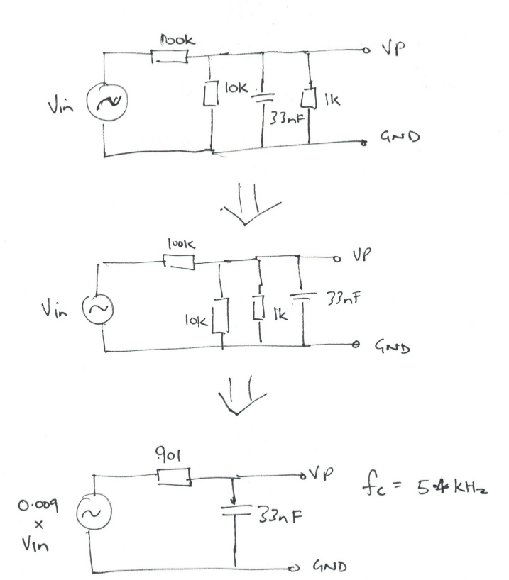
you’ll see the divider is much more than the 100K/10K suggests. In fact the 10K is kinda’ irrelevant since it’s in parallel with the 1K.
I’d second Robert’s suggestion of a power supply and a separate voltage monitoring circuit… but in the meantime (and I’ve not read back over all the things you’ve tried so you may have rejected this one already) did you try limiting the current with a series R between the diode and the 220uF cap, like the OEM design does?
For that to be useful, you need rather a lot of excess voltage. I’ve not checked the details, and if you don’t have that, it can’t be done. [The explanation is the average current passing to the regulator must remain the same. Increasing the ripple voltage seen by the regulator allows you to reduce the current as it flows for a longer period of time - because it starts earlier in the cycle. Reducing the current reduces the voltage drop at the transformer terminal.]
By that, do you mean instead of just a voltage divider, a small transformer?
There’s a reason I did this initially, and I’m pretty sure I was seeing interference at a specific frequency. It was probably only present on an earlier revision with a different power supply, so it’s possible the interference isn’t even there anymore. The reference design has all 18nf caps on everything.
You’re right, it is 5.4kHz - I did a quick calculation and didn’t take everything into account.
That wouldn’t work for this application (as Robert explained) since I’m only coming down from ~10VAC.
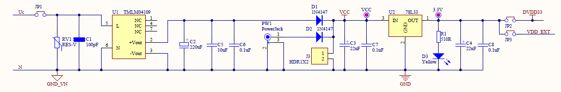
With the Atmel demo board, they have the series R for the voltage reading, an on board AC/DC power module (that outputs 9VDC), then an LDO for 3V3:
For best noise immunity you really do want the same filter on both legs of the amplifier.
The OEM design uses a linear regulator where yours is a 3.3V switcher. It looks to me like you’ve got heaps of headroom to play with there. Your Pink trace above is in AC mode so I can’t see absolute values but it looks like a little over 2V peak-to-trough? With 10VAC the peak should be about 14V, or 13V say if you have a 1V drop along the way, so is the Pink swinging between about 11V to 13V? How low does that get when the ESP is in full blown wifi transmit mode?
That’s all connected to a very low impedance source (the grid) so there’s really no risk there of their power supply putting a divot into their voltage measurement.
I realized you meant something like this: Buffered Voltage Bias — OpenEnergyMonitor 0.0.1 documentation
Yeah, I’ll definitely make that change for the next version, thanks!
You’re very close! Between 10.88V to 14.4V. This is with the ESP32 transmitting in AP mode, which uses the most power. The issue I had early on was actually getting enough current out of the power supply to power the ESP32. At the least I need 400mA.
A resistor between the diode and the cap shouldn’t affect that. We’re not talking about putting a resistor between the cap and the switcher - that would be bad. A resistor between the diode and the cap will just slow the charging rate of the cap, spreading it further across the cycle and reducing the big in-rush. That should have a noticeable effect on the size of the divot.
No, I didn’t mean that. That is providing a buffered BIAS for the inputs - which you can use instead of multiple pairs of equal resistors and capacitor when you have a single-ended input that requires the quiescent voltage to be mid-rail.
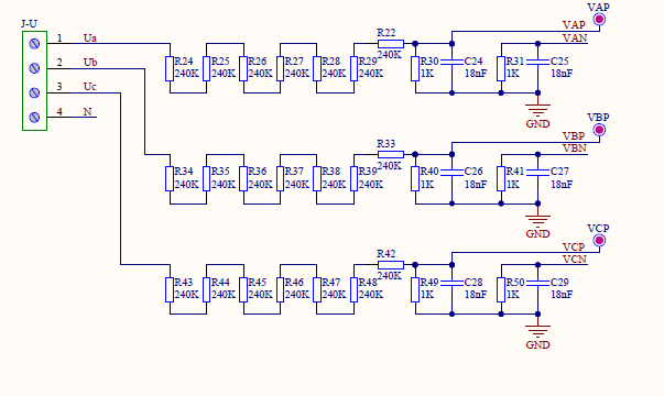
What I meant was a means of safely obtaining an isolated image of the mains voltage wave. Your demo board gets its sample via that chain of resistors (R24 - R22 etc). That’s OK for people who know what they’re doing, but if you’re putting this together and making it available to people who aren’t necessarily aware of the dangers, I wouldn’t recommend it because the left-hand end of those resistor chains (R24, R34, R43) is at full line voltage and fault current.
I’ve thought about, but haven’t tested, a ZMPT101B 1:1 c.t. That should - operated at the correct current - give an isolated and reasonably accurate voltage sample. It should give better fidelity than most a.c. adapters, because these are normally designed as a power supply where accuracy of the waveform is unimportant.
ohhh, I see - I’ll definitely have to test this. Thanks!
Oh, okay - thanks for explaining. I’m definitely not going to use resisters to bring down full mains voltage, don’t worry. ![]()
Funny, I was literally just looking at that and the SPT204AD. I’m not sure if the latter is made anymore though.
That might be a good time to re-assess that voltage divider too. 100:1 has your 10VAC down at 100mV which means you’re operating in just the bottom 14% of the IC’s range. It’s no doubt got the amplifiers and dynamic range to drag that back up again to something usable but you might get better results if you don’t take it that low in the first place.
“might”? I would have thought “almost certainly will…”
Fair enough, although I’m regularly blown away by the dynamic range of these energy ICs. I recently plugged the output of a 12VAC wall-wart into my V input - which is designed for max 270VAC - and the performance was spectacular (but for the phase error it introduced).
When I stopped to think about it I concluded it wasn’t that surprising. They tend to use the same processing path on V as they do on I, and 12V into a 270V input is the equivalent of ~2A going into an I input rated for 50A which they can easily deal with. A dynamic range of 1000:1 is pretty common on most of them.
But in this case there really is no reason to take the voltage that low.
1 Like
Right, I agree - that’s another thing that will have a little revision in the next version. Some people had difficultly calibrating to 240V if using a 9vac transformer (which is a number 0-65,535). To get to 120v it’s around 30,000.
Apart from that, I calculated, and compensated for, a 2.5 degree error with the 9vac transformer that comes with the kit for 120V people.
Yeah, the ATM90E32 is 6000:1 for active energy, according to the datasheet. But yeah, still no reason to not let in some more mV. Even if it were to get a bit warmer, there is temp compensation too.
The statutory voltage limit in the UK used to be 240 V + 6% = 254.4 V. It’s very likely that this voltage will still be reached occasionally, for some consumers. It’s now 230 V + 10%, but I don’t think there’s been a rush to replace all the transformers.
I followed one of your links above re 240V and came across…
 ////// VOLTAGE
  if (LineFreq == 389) {
    //if 50hz then voltage is 240v and needs to be scaled
    voltageA = eic.GetLineVoltageA()*2;
    voltageC = eic.GetLineVoltageC()*2;
I don’t think that’s a safe assumption. There are a handful of countries (Jamaica maybe?) that use 50Hz 120V.
Good to know! I’ll have set that using another method.
Although we (those of us in the US) tend to think of our system as 120 VAC, it’s actually
a 240 Volt system as well. (a single phase split into two 120 Volt “legs” WRT residential service)
I’ve seen my voltage (I’m in rural Oklahoma, so the power system here tends to be flaky)
go as high as 256 Volts, which is in line with what Robert described.
And I’ve noticed that some “universal” devices specify up to 270 V.