Excellent! As @Robert.Wall says you’re now well positioned to generate a phase error Vs primary current plot for your CT. It’ll all be net (relative to your VT rather than absolute) but it’ll give you a feel for how much it varies across the range (assuming your grid voltage stays stable enough that the VT part of shift is stable-ish). Then you can decide whether it’s worth invoking the IC’s 3-segment adjustment.
[EDIT] Speaking of grid voltage, is it really as low as 96V, or is that uncallibrated?
Yes, kind of - it’s specific to the IC and how they describe to set offsets in the documentation.
I’m going to do more tests on a full load soon.
It should be more stable via the plug coming right off of my panel. I was getting 96 because of a high load on a circuit that’s probably the farthest from my panel, and close to the max amperage.
I think that’s your scope’s persistence telling you there are regularly two different voltages, probably depending on the state of that reservoir cap and the ESP processor. That all goes away when you unplug the ESP right?
I fear that could be another obstacle to being able to calibrate to 1% with the Voltage waveform jumping around like that (when the grid isn’t).
It could be the grid, but much more likely the load changing as you (@dBC) suggest - caused of course by the non-zero impedance of the a.c. adapter.
This is why the emonTx is limited to only one temperature sensor - even the RFM69CW must not be operated on full power when the unit is supplied only by the a.c. adapter - because drawing a variable current, whether it varies during a cycle or longer is largely immaterial, means that the measured voltage is also varying, and that spoils the accuracy of the measurements.
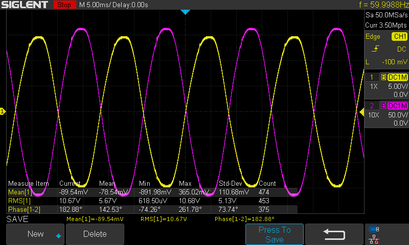
What’s the load out of interest? Any idea what’s going on with the purple positive peaks in the first shot? They seem way distorted compared to the Yellow, but only on the positive peaks, the negatives look much better. It looks to be coincident with a little disturbance on the Yellow which might be caused by your DC cap charging up, but I can’t immediately think why that would disturb the load and/or CT output (Purple).
The load is a hair dryer. I have to do some more testing, but the positive peak divot may be because of the SMPS, yes. I tried with a 100uf cap, but it isnt stable enough to power an esp32 on startup.
My board is going to arrive soon. Seeing your scope captures, I’m a bit concerned about the voltage waveform. Won’t those harmonics cause measurement errors (first image, yellow trace). Is it possible to add a separate power source somehow and only use the transformer for voltage sampling, to eliminate this distortion?
Oh good, I’m glad I was able to get to yours last week! There’s still a lot of manual processing that has to take place, like testing and assembling kits.
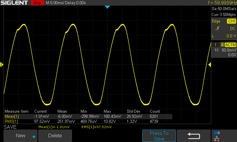
The first capture on this thread was from a previous version. I’ve since added some more caps to the latest, and changed the SMPS to a different IC. This is a capture from the current meter with a ESP32 hooked up:
The divot is still there from the half wave rectifier/220uf cap, but it’s no longer as flat at the top and bottom.
One thing I’ve learned about this IC, through testing different designs, is it’s very good at filtering out noise. I’ve tested this extensively against other meters and it’s always right on.
I haven’t tested this, but if you wanted to only use the AC transformer for reading voltage, theoretically you could de-solder the rectifier (diode) to the left of the transformer jack, and use a usb phone style DC power adapter to back feed 3V3 though the ESP32 usb jack. There’s nothing preventing the 3V3 pin from being back fed.
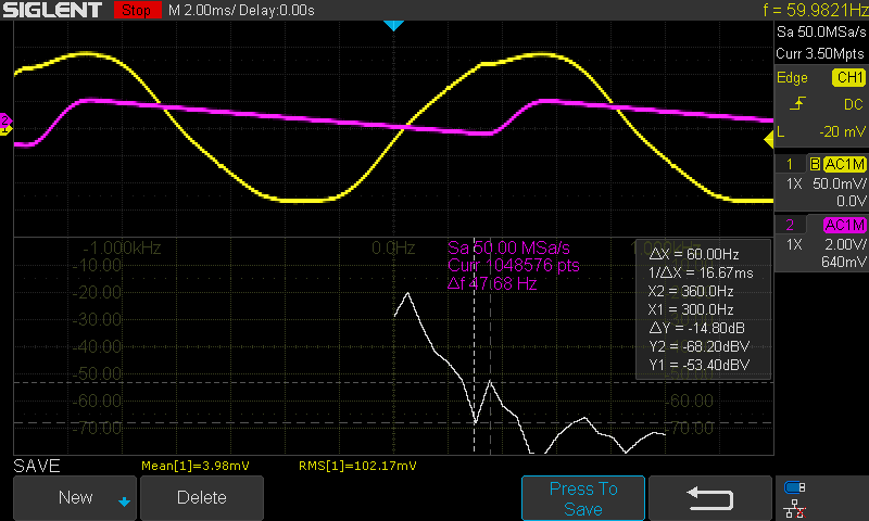
It can’t distinguish between noise and signal other than by frequency. Generally you pick a cut-off frequency and declare everything above that as not of interest and filter it out. A typical value for that might be somewhere in the 2-10 kHz range when measuring mains power. Can you get your scope to do an FFT of that distorted voltage signal? Is that signal as measured at the input pin of the IC?
Thanks. When it arrives (maybe this week, possibly the next), I hook it up in parallel to a MODBUS capable revenue grade meter for comparison/voltage calibration. I might not need that extra voltage input but I think it would be a useful option for later revisions of your board.
Right, you are correct - bad choice of words on my part. What I meant was that it’s very consistent with reading voltage (and current). The physical anti-aliasing filters for voltage are 4.82kHz for VN and 8.84kHz for VP.
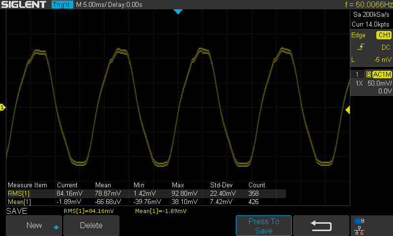
Sure! While I was at it, I put a probe on the cathode of the half wave rectifier. The result makes sense. The voltage signal was measured at the input, yes.
I’d be interested in ways to improve upon this for a future revision.
I’d be very interested to see the results!
FYI, for 240v, I’d recommend a 12v AC transformer. With the version of EmonESP that is loaded on the included ESP32, there is 2x scaling done in software. This was done because if someone used a 9v supply the calibration value for voltage would sometimes exceed 65k and not be able to calibrate to 240v. You’ll probably want to remove that scaling if you want to get more accurate metering values directly from the meter.
Actually, if soldering on a header is easier than removing the rectifier in order to not use the on board SMPS, you can sever JP3 jumper and read voltage on that channel instead. That modification would have to be made in software too.
Thanks for the heads-up. To sum things up: I need to remove the doubling of the voltage sample and also the doubling of the power related values, right? I will first use the board as is, with a 12V AC/AC supply, do calibrations and let it run for a while. I’ll also change the code a bit more to sample 2 independent current channels as I have a single phase 230V nominal feed (in reality, it’s some random value centering around 240V±10V) and solar power, so I need a single voltage channel and 2 current channels, where one represents export/import power and the other the solar generation. The power meter chip handles the channels independently (leaving sums aside for now), so hopefully it will work like that. I ordered the bare board so I’ll use one of my NodeMCU boards (ESP8266) for interfacing.
I’ll try to post some calibration results when I’ll be gone through that and have some data collected.
What you have there is an absolutely classic picture of charging the reservoir capacitor in the power supply and the effect that transformer impedance and any other series resistance has on the voltage. Apart from a second transformer so that you can separate the functions of power supply and voltage monitor, all you can do is ensure the current demand of the unit is the absolute minimum, and the transformer impedance too is the absolute minimum.
That’s what I figured. I’ve done a lot to reduce the power consumption of the ESP32 in software.
How about using 2 power supplies? One with a half wave and LDO (to power the IC, and LEDs, which is about 40mA) and one full wave and SMPS, with a separate isolated DC ground, to power the hungry (up to 500mA) ESP32.

