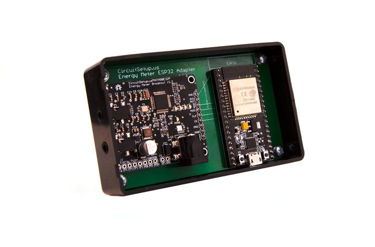
I thought people here may be interested in a new energy meter project that uses EmonCMS. It’s designed for monitoring electricity usage in your entire home. It’s a lot like emonPi, but has a dedicated energy monitoring IC (the ATM90E32), and can use any Arduino style MCU. I previously got some advice on this forum when I was designing it. Thanks for that!
The wire windows in the CTs you’ve chosen are too small to fit the 4/0 Service Entrance Wires typically found in a US residential load center. (assuming whole-house vice branch circuit monitoring) Is a suitable substitute available?
I’m glad someone finally noticed this! I realized that most newer homes are 200A and have aluminum (not copper) service mains after the pictures were taken of the SCT-013 CTs. In the description this was changed to the SCT-016, which has a larger 16mm opening, rated for 120A, and will be ordered with 3.5mm plugs.
Almost the same IC. His uses the ATM90E26, mine is the 32 (which actually has 3 current channels, but I’m only using 2) Although I think he did make one with the 36. He had posted Arduino libraries for all 3, but the 32 wasnt quite finished. I finished it, and configured everything for 60hz US power, to work as split single phone, and work with EmonCMS.
I’m curious as to how the AC waveform looks when that 220uF cap starts conducting. If you look at the corresponding OEM design: https://github.com/openenergymonitor/emontx3/blob/master/hardware/schematic.png
you’ll see they went to some effort to reduce the size of the divot the DC supply puts into the AC waveform so as to limit the distortion seen by the V measurement.
Sorry I initially overlooked your post! Luckily there are anti-aliasing caps on all inputs. The AC signal goes right from the AC transformer input, through a voltage divider, and to the IC for measurement. The 220uF is after the half rectifier, and before the SMPS.
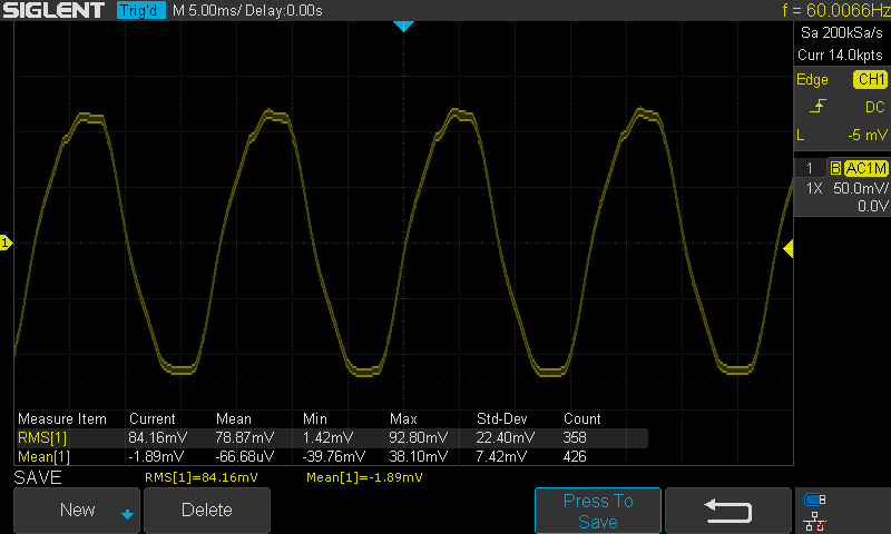
This is from the cap right before the voltage input (C5 - VAP):
To put it simply, it can calculate more data, and do it in real time. It’s also smaller and cheaper in price.
It does not have a pulse sensor since it doesn’t rely on your meter, but current transformers to read current directly from your panel. It does have its own pulse outputs though.
Yes, it can monitor any 2 current channels. It has “Split-phase” in the name because the kit comes with 2 current transformers that can monitor 120A each. You can connect almost any CT rated at 200 Amps (or less) to it.
The AC transformer signal is run though a half rectifier, before going through an SMPS to output 3.3V DC. This is what @dBC was asking about above in a different way.
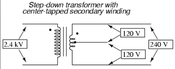
It would be more accurate to say it has split-phase in the name because that’s what the US
residential electrical system is called. It’s a single phase,split into two “legs.”
Like so:
2.4 kV has largely been superceded by 7.2 kV, but there are still many 2.4 kV systems in operation,
especially in small towns.
The center tap is grounded to earth at the transformer.
I mention it because an emponPi/emonTx can use two current transformers.
(the “Tx” can use as many as four CTs)
Honestly, I get a similar sine wave directly off of the AC transformer. I’m sure it doesn’t help that my 3d printer was running. Actually, I’m positive that contributed to noise.
The transformer causes the flattening at the peaks, but do you get the “ledge” your scope trace shows near the positive peak? (as well as the “bump” at the top of the positive peak)


