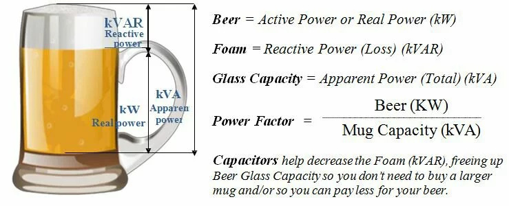
That sounds more familiar, I think the beer diagram misleads by all the lines being vertical, suggesting the apparent power is a sum of the real and reactive powers. If the real and reactive power lines were drawn at angles (so as to create a right angle triangle with the apparent power as the hypotenuse) it would be a better illustration. Clearly beer doesn’t help when learning about electricity! Who knew?
However I still think that even though the “difference” is not equal to the reactive power, the difference IS still a value that can be used to reach a better phase calibration than just observing the PF or peak real power. The “difference” would still be 0 when the reactive power is 0 (aka unity) correct? It just won’t be the VAr.
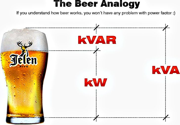
Holy cow, what is it about beer diagrams to demonstrate this?
No, I am convinced, just curious too! I learnt most of this at school (when I wasn’t bunking off that is) and a lot has happened since then! You tend to eventually forget stuff you don’t use much.
Does it need “to be measured” ? Since real and apparent powers can be made available on the emonTx/Pi (non-standard sketches), it wouldn’t be impossible to derive a fairly accurate VAr from those (either within the sketch or even externally just for calibration), essentially just magnifying the “difference” nearing a zero value (for those of us not particularly interested in VAr otherwise).
Real and apparent power are available in the standard sketches - it’s just that apparent power isn’t normally sent out.
Oh yes it would (be all but impossible), due to rounding errors in the maths and even more so by the effect of the amplitude error that PHASECAL introduces.
What you need to do is store one set of values (probably, but not necessarily, voltage) and delay them by 90° and then multiply the V & I samples - that will give you vars directly. And that implies phase locking to mains frequency if you need accuracy, though if you’re only using it to adjust PHASECAL, anywhere close is good enough, because all you’re interested in is adjusting for a null.
I doubt that (but it’s possible). I’d much prefer to believe you have a 1.3° phase shift somewhere. Do you really have a pure resistive load? Take a good hard look at your circuit and see if you have picked up a phase shift, or a combination of several, maybe the result of stray capacitance.
I mentioned the code because there was an issue with that and other specific 32 bit registers. In the code for the official demo board, there was a function that made it impossible for that value to be negative, which I have no idea why that would have been done.
If it is the result of a capacitor, it’s probably the same 250uF one that is putting that dimple in the AC sine wave. Does that reactive power reading mean that some of the load is being transferred TO that cap?
Btw, I did a test with a 100uF cap in the same place, but it only made a nominal difference in the sine wave.
Me neither. If you can have consumption and generation, you can have positive and negative real power. If you can have inductive and capacitive loads, you can have positive and negative vars.
I think a meter manufacturer might know what they’re talking about:
I’d forgotten what the circuit diagram looked like. That is undoubtedly what it is telling us.
@jdeglavina What are the v.t. & c.t? What numbers do their manufacturers give for the phase errors?
Have you looked at the tests that I’ve done for our ‘economy’ v.t (a.k.a a.c. adapter) & c.t? The phase errors of those - and particularly the way they vary with the measured quantity - is quite revealing.
It’s a yhdc sct-016 for the CT and Jameco Reliapro 9v 1500mA VT. The data sheet for both do not list a phase error. The CT has a spot for it, but nothing is filled in, and the VT doesn’t have anything listed at all, rather. https://www.jameco.com/Jameco/Products/ProdDS/112336.pdf
If you’re looking to prove that the measurement electronics is correct, you need something a bit different to those.
What I’d be tempted to do, if the data sheet allows this configuration, would be to use a shunt for current and make direct connections without transformers.
To do it safely, get a low voltage isolating transformer (so that you’re isolated from and not messing about with the full mains voltage), and a pure resistive load to match the transformer rating. Also a non-inductive shunt, in place of the c.t., that will give you the required voltage at the load current. You’d need to change the voltage input divider temporarily. The isolating transformer won’t affect the measurement.
Alternatively, you could invest in a metering grade v.t. & c.t., which would both have phase errors - but you’d know what those were.
As it stands, your measurement shows that the difference in the phase errors of the combination of the YHDC and the Jameco has come to only 1.3°, assuming your electronics is correct and has no phase or timing error.
You could try measuring the phase errors with my soundcard method, but you need to be meticulous with your test rig because it’s very easy to introduce an error with even the capacitance of a foot or two of screened cable.
After doing some more math, and writing some new functions, I think I got this pretty close to what it should be:
Voltage 1: 96.39V
Voltage 2: 96.67V
Current 1: 11.81A
Current 2: 0.00A
Active Power: 1138.87W
Power Factor: 1.00
Fundamental Power: 1136.99W
Harmonic Power: 1.88W
Reactive Power: -0.70var
Apparent Power: 1138.31VA
Phase Angle A: 360.00
Chip Temp: 31.00C
Frequency: 60.00Hz
Presumably, your new functions allow you to trim the phase compensation to suit that particular pair of v.t. & c.t. at that particular voltage and current.
I’d be interested to see if, when you repeat that at a range of currents (and possibly supply voltages, though the effect of that is likely to be less pronounced), you see a change in phase angle that’s in line with what I’ve seen with the YHDC SCT-013-000.