New Open Source Split Phase Energy Meter that uses EmonCMS

I know, but I have a half rectifier before the SMPS input, so anything less than 100uf and theres not enough current to power everything.

I actually designed a 3 channel that can fit an esp32 on top, and a 6 channel:

That can have add-on boards stacked

This looks nice. A few questions:

  • What is the expected accuracy of the device? Will it support calibrated CTs?
  • Is it applicable to a single phase + inverter system on 230V?
  • Will there be an option to add a separate supply for powering electronics (so the transformer is only for waveform capture)?

That is likely to be a significant factor. The fewer disturbing influences where the fault level is the lowest, the better (from the point of interference and waveform purity, etc.).

(And I think it could be hundreds in some cases.)

Gotcha.

Oh, BTW, that’s half wave rectifier, vice half rectifier. :wink:

This looks nice. A few questions:

  • What is the expected accuracy of the device? Will it support calibrated CTs?
  • Is it applicable to a single phase + inverter system on 230V?
  • Will there be an option to add a separate supply for powering electronics (so the transformer is only for waveform capture)?
  1. Assuming it’s calibrated to the CTs that are being used, it is 99% accurate.
  2. For 230V you’ll need to use an AC transformer that can bring down the voltage at least 12v
  3. I don’t currently have a plan to add an option to power electronics only. However, if you really want to you could just take off the diode right next to the power jack, and hook up the 3V3 pin to power.

Thanks.

  1. I think you meant 1% accuracy :slight_smile:
  2. The transformer is not an issue, the question is, will it support a 230V system? That would need other calibration values, etc.

Yes, it’ll support a 230V system. It would need to be calibrated for the transformer, correct. That procedure is outlined here

There is a parameter in the library for 50hz power as well.

You might struggle to get 1% accuracy without including some phase angle calibration. Those VTs and CTs each introduce phase shifts in the signals you’re measuring. The IC supports being able to add delays in the V or I down to a resolution of ~488nsecs to compensate for that, but the library you’re using appears to just hard code all those registers to 0 (unless I’m missing something that happens elsewhere?).

  CommEnergyIC(WRITE, PQGainA, 0x0000);     // Line calibration gain
  CommEnergyIC(WRITE, PhiA, 0x0000);        // Line calibration angle

And those phase shifts may well vary with the amplitude of the quantity being measured. Though this is very much a second-order effect, it could be important with small, low power factor loads in particular.

I’ve not drilled down into the details, but one of the headline features in the datasheet suggest they’ve even considered that:

.Flexible piece-wise non-linearity compensation: three current (RMS value)-based
segments with two programmable thresholds for each phase. Independent gain and
phase angle compensation for each segment.

Now that’s interesting.

Considering only our “shop” c.t. and v.t., the c.t. would need to use all 3 segments (in a ‘bathtub’ shape) while the v.t. is close to a straight line over the operating range.

That might also be helped by the lower voltages. Looks like full deflection on the inputs is at 720mV (RMS).

As high as that? Certainly it will help - it’s better than 1.1 V rms, and as we all know that a c.t. is at its best working into a dead short, but it also means the wide range of ‘economical’ 333 mV c.t’s are of limited use, which is a bit of a shame.

Right. I need to test some things there. To do it right you would need to calibrate the phase offset as well, but I dont have a device that can measure and do that against the meter.

I have thought about getting a large motor-run capacitor - use that as a load and adjust for zero real power…

As a starting point, you could try a very heavy purely resistive load of maybe 8 - 10 kW (thread the primary through the CT multiple times if you don’t have a load that big). Make sure the load has no reactive components at all - so no fans and no electronics… a big fat heating element would be ideal. Then read the reactive power from the IC. If there are no phase errors that should read as 0.

Both @dBC’s and my suggestion amount to the same thing.

For the emonTx, the only practical method is to adjust for unity power factor with a pure resistive load. The problem with this is you are trying to find the maximum on the flat top of a sine wave - it’s not very precise. It is much easier and more accurate to (in my suggestion) look for a zero crossing of real power with a pure reactive load, or dBC’s rather more practical suggestion, as you have reactive (imaginary) power readings available and a pure resistive load is not hard to find, of looking for a zero crossing of reactive power - where it switches from inductive to capacitive.

Just to sure I’m getting the right picture here, by reactive power, we are simply talking about the difference between the real power and apparent power? Although it had never occurred to me before (although so obvious now!), I can see how focusing on reaching 0VAr might be easier than aiming for a unity PF of 1.00000, even if it is just the number formatting or magnitude (no decimals) that just make it appear simpler.

I understand it doesn’t change the “flat top of a sine wave issue”, but aiming for a constant 0 (or as near as possible) might just be easier on the eye than a unrounded PF and more accurate than a rounded PF. I used to try and tune for the peak realpower, but even that can vary on temperature etc or indeed be less easy on the eye, never considered using the difference rather than the PF or peak realpower! good idea!

Ha! Just found this picture (from Reactive Power Compensation of Reactive Components)

image

I’ve always found beer helps when learning about electricity :smile: (Joking!!! - don’t try this at home kids)

2 Likes

I’ll drink to that! :grinning:

It’s not as simple as that.

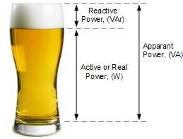
Sadly, that’s wholly inaccurate. What you should be looking at are two vectors - real power and reactive power are mutually at right angles, and apparent power is the hypotenuse of the resulting triangle.

See: AC - Active, Reactive and Apparent Power

I was taught “imaginary power” rather than “reactive power”, which is rather apposite, as there’s actually no power transferred at all - hence “imaginary”.

In this diagram (from the link above - and we’re talking about the hypothetical pure sine wave here), P is real power, Q is reactive power, and S is apparent power.

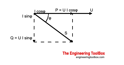
Now if you’re thinking of phase errors, φ can represent the phase error in the measurement. When it is zero, the Q vector collapses to zero, and P & S are equal in length and coincident. Their ratio is also cos φ and is equal to 1. Now if φ changes either way by a few degrees, you can see that while S remains the same length (because VRMS & IRMS don’t change, so their product S doesn’t change), P becomes shorter but by a tiny amount. It’s hard to find that peak.

Now look at it when you are measuring reactive power (which the emonTx/emonPi standard sketches can’t do). A small change of φ either way by a few degrees makes Q change sign, and change by a much larger amount too.

If you’re still not convinced, look at the difference between cos(0°) and cos(2°),
and sin(0°) and sin(2°).

For anyone without a calculator handy, the numbers are 0.000609 and 0.0349 - the difference is 57 times bigger.

1 Like