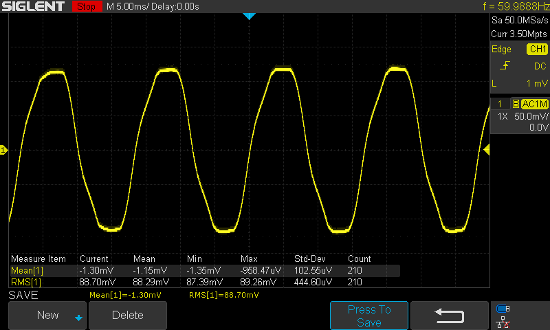
Here’s a trace I just did with less interference. Same location right next to the voltage reading input:
The problem is not the noise but the constant distorced sinewave, Bill is right its usualy the transformer causing that. Naybe it’s saturating, check if it gets warm even unloadad and try to measure just the transformer output unconnected.
Usually smaller transformers have cleaner sinewaves.
I’ll get a shot of just the transformer. The wave looks almost identical. It’s a 9v 1500mA Jameco AC Transformer.
What you really want to do is compare the V signal going into your IC with the what the grid looks like. You can get a safe approximation of what the grid looks like with a CT+burden wrapped around a large resistive load. Ideally keep the burden small so the CT doesn’t distort - feed the primary through the CT multiple times if you need a bigger signal.
If your scope is dual channel you should be able to compare them right on top of each other (give or take a bit of a phase shift each will introduce). I could believe the flat-topping is what the grid is actually doing, but the kink on the way up might be an introduced error.
How’s this?
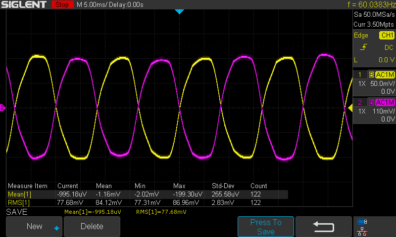
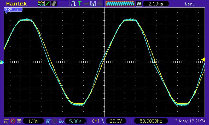
This is with a 5A load across a CT (purple), and the voltage measurement going into the IC at cap C5 as before (yellow).
That’s the idea. How’s it look if you flip the CT so they sit on top of each other?.. i.e in phase rather than out of phase.
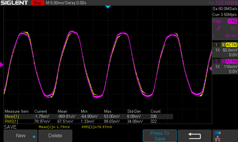
Yep, it does. And that’s with the ESP in full power wifi tx mode? That’s probably your worst case current drawer.
Actually, I should have had an ESP connected. The only load in that case was the IC itself. With the ESP connected and transmitting wifi and SPI signals, it looks more like the first graph I posted. I’ll be adding some bypass caps on the 3v3 output. The good news is the IC is able to filter out any noise regardless.
That’s what I too suspected would happen. The source of the problem is the non-zero impedance of your 9 V transformer, which means that the charging current for the 220 μF reservoir capacitor creates a voltage drop inside the transformer (and in the connecting cable too), and it’s that which puts the step in the waveform you’re trying to measure.
Does that mean you ignore any power in the harmonics, or just the high-order ones?
Hi Robert - thanks for chiming in! I would imagine a more expensive AC transformer wouldn’t have this problem. Do you think some extra bypass caps and/or a ferrite bead on the 3V3 out would help with this?
Yeah, it would only be high frequency filtering. There is a way to calibrate an offset if interference is too much.
Sounds like you might be a tad confused, John.
The flattening seen at the waveform peaks is caused by the transformer.
But the “gouge” (for lack of a better term) that’s in the waveform (near the positive peak)
is caused by the 220µF cap you’re using. Replace it with a 10µF cap and you should
see an improvement.
The emonTx does use the same power supply to meet the DC needs of the device as well
as provide an AC waveform sample, BUT, the max current draw from that power supply is very limited.
IIRC, the absolute max is 60 mA, but the recommended max is 10 mA.
From the wiki page:
- Important note regarding powering with AC: Only recommended for standard emonTx operation without auxiliary sensors (apart from a max of 4 DS18B20 temperature sensors) or equipment (e.g. relay modules) connected. Correct operation via the AC supply is critically dependant upon using the correct AC-AC adapter. If you are using the recommended adapter, the current draw exceeds 10 mA, and mains voltage is below the allowed minimum, circuit operation will be impaired adversely affecting the accuracy of the emonTx. To avoid damage to the emonTx v3 circuits the current drawn from the AC circuit should never exceed 60mA - see the technical wiki for more info. If more than 10mA of current is required, it is recommended to remove jumper 2 (JP2) and power the emonTx via the 5V USB connector. If an AC-AC adapter is connected it will be used only to provide an AC sample when JP2 is removed.*
A better solution would be to use a separate DC power supply.
This is a property of all transformers, so I’m afraid you’re likely to be stuck with it. The magnitude of the impedance might be somewhat less with a higher-rated transformer, but other factors, like phase shift, could easily spoil everything.
Not really. If you do filter (excessively), you’ll end up not measuring the power in the harmonics, which will introduce a deliberate error. It ought not to be a large error, because the power in the harmonics should, if your loads obey the rules, be small. But you don’t know that they do and whether it is or it isn’t negligible.
In part, also by every other Tom, Dick & Harry who has exactly the same sort of power supply (except probably using a full-wave rectifier) hung on the system and all pulling current just at the peaks.
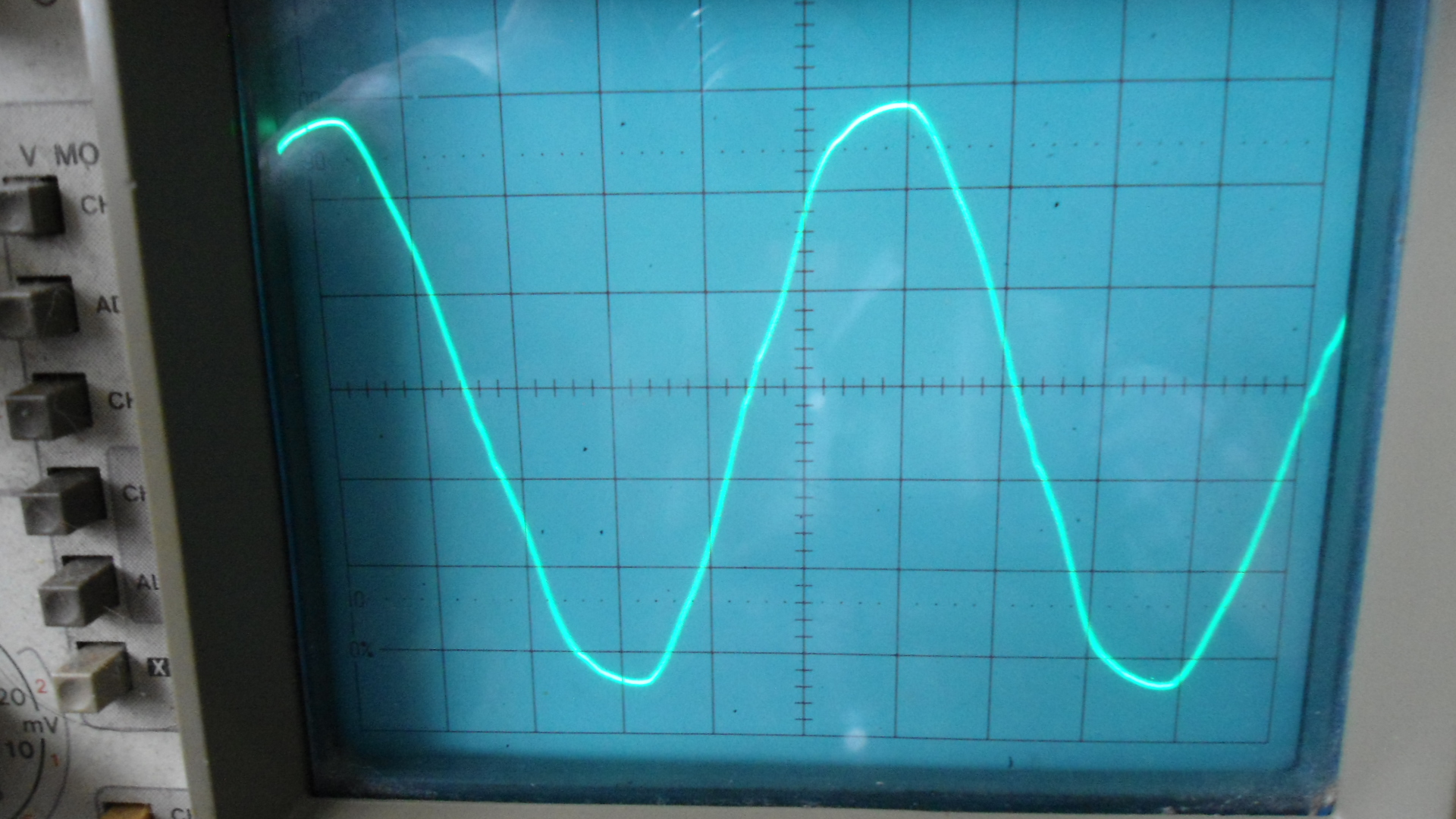
If I look at my UK mains waveform directly (×10 'scope probe), then I see pretty much the same degree of flattening as I do from the TDK a.c. adapter.
[Picture is below.]
Thanks Bill. You’re right, I read that incorrectly, thanks for explaining. That makes sense, but I probably cant go with that low of a cap without causing other problems with the SMPS.
Here you are:
The yellow trace is the raw mains, the blue is a standard TDC UK a.c. adapter, unloaded.
It is very clearly “flat-topping” on the mains supply itself.
Given we typically have 1 to 6 houses on a single transformer vice the 100 or more you have in the UK, would you say that’s why my waveform isn’t flat-topped? (although it clearly is distorted)
Application note Basic Calculation of a Buck Converter’s Power Stage (Rev. B) says:
6 Input Capacitor Selection
The minimum value for the input capacitor is normally given in the data sheet. This minimum value is
necessary to stabilize the input voltage due to the peak current requirement of a switching power supply. The best practice is to use low-equivalent series resistance (ESR) ceramic capacitors. The dielectric material must be X5R or better. Otherwise, the capacitor loses much of its capacitance due to dc bias or temperature. The value can be increased if the input voltage is noisy.
The data sheet says:
9.2.2.5.2 Input Capacitor
For most applications, 10 μF is sufficient and is recommended, though a larger value reduces input current ripple further. The input capacitor buffers the input voltage for transient events and also decouples the converter from the supply. A low ESR multilayer ceramic capacitor is recommended for best filtering and should be placed between VIN and PGND as close as possible to those pins.
Why not use the third channel for PV monitoring?