What’s the reasoning behind them being different? They form a differential input so normally you’d keep things nice and balanced on each side (and I think maybe you’ve got VN and VP around the wrong way above). By my reckoning the VP filter is 5.4kHz. I also noticed in your scope traces you’re getting quite a small V swing of about 100mV while the maximum deflection for your IC is 720mV.
I wonder if your voltage divider and LPF are working the way you think they’re working. If you have a look at the Thevenin equivalent circuit:
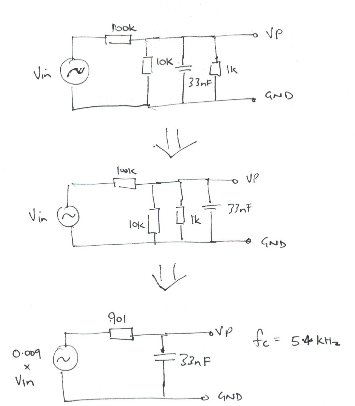
you’ll see the divider is much more than the 100K/10K suggests. In fact the 10K is kinda’ irrelevant since it’s in parallel with the 1K.
I’d second Robert’s suggestion of a power supply and a separate voltage monitoring circuit… but in the meantime (and I’ve not read back over all the things you’ve tried so you may have rejected this one already) did you try limiting the current with a series R between the diode and the 220uF cap, like the OEM design does?