I used this: https://www.buyinsulationonline.co.uk/product/armaflex-pipe-insulation-nitrile-rubber-black-pipe-lagging
and this:
https://www.buyinsulationonline.co.uk/product/armaflex-insulation-tape
I used this: https://www.buyinsulationonline.co.uk/product/armaflex-pipe-insulation-nitrile-rubber-black-pipe-lagging
and this:
https://www.buyinsulationonline.co.uk/product/armaflex-insulation-tape
Double up the pipe insulation.
I’ve used this K Flex – Rubber Pipe Insulation | insulationandlagging.co.uk and doubled it up as for 22mm pipe, 22x13 gives an outside dia of 48, then use 48x13 - total 26mm of insulation on 22mm pipe. for 28mm pipe, 28x13 + 54x19 works as well ![]()
The thermostat will be triggering the valve, which triggers the pump once opened.
Make sure both the UFH and DHW are off (then try for each).
Often these valves have a manual lever on the side that will trigger the pump if the valve is opened manually.
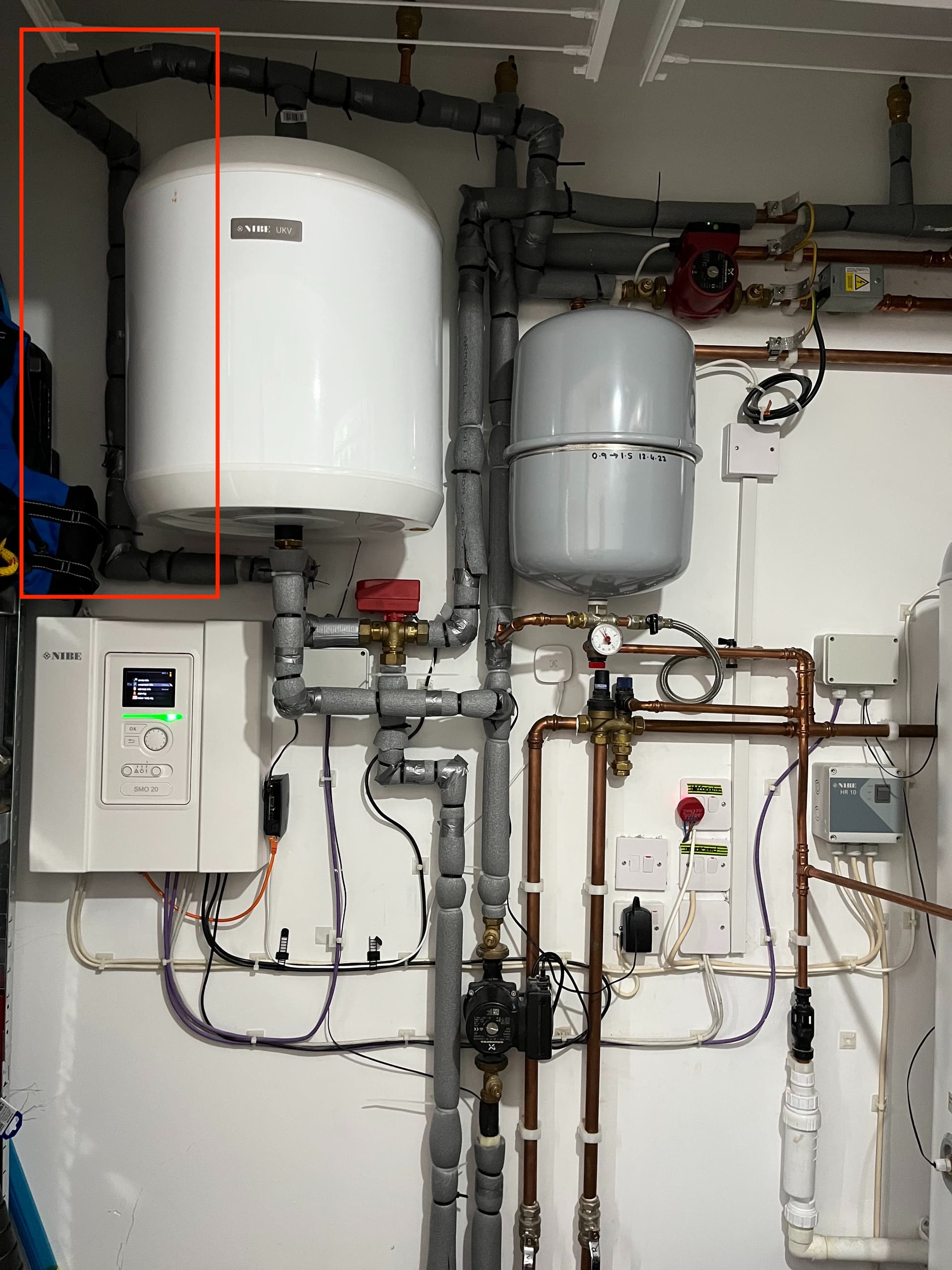
Thanks for those excellent extra photos Nick; they complete the picture of how your system is plumbed.
So if the Radiator pump and the UFH pump are both running, that’s two pumps working in parallel to pull the heat pump Flow water from that Tee fitting above the Buffer Tank, so not surprising that they’re capable of ‘out running’ the Charge pump (and pulling cooler Return water up through the Buffer Tank).
I’m pushed for time now but I’ll post a schematic of my own system later, for comparison purposes.
The pipe insulation is 25mm, 35mm outdoors. There’s not room for more insulation where pipes are run in parallel.
I’ve got some joints and beds to tape up, so further improvements still. Also, I’m not crazy about insulating everything. The room has MVHR extract and so any lost heat is redistributed around the house anyway.
So, UFH and rads are pretty much running constantly after following this HeatGeek video which essentially argues against zoning and turning off rads in used rooms to maximise the thermal footprint available to the ASHP and increase efficiency.
Whilst the rads do have Tado TRVs, they are set to be open all the time unless solar gain makes the room uncomfortably warm. Same with UFH.
All the rads and room sensors feed back to the SMO20 which averages the temperatures received and works to that figure, I guess.
In summary, rad pump and ufh pump running all the time, drawing about 90w.
Water is leaving the buffer tank from the top of the tank? That would explain why flow and return are so close… How to fix this, turn down the red pump?..
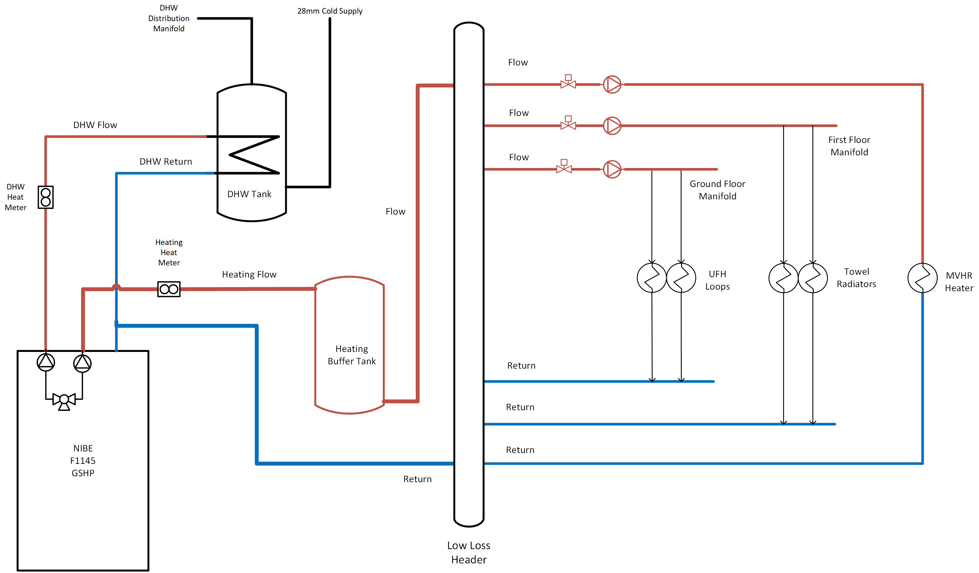
Here’s the schematic of my system for comparison:
I should add that this is very firmly Not To Scale! The Low Loss Header is nothing like that big in reality.
Also worth noting that I contracted one company to install the heat pump and its ancillaries whereas my builder used a different company to do the heat emitter circuits along with the rest of the plumbing in my self-build, so I had to make it clear who was quoting for which aspects. This schematic dates from that time, where we agreed the builder was responsible for the LLH and everything to the right of that, with me contracting separately for everything to the left of the LLH.
If cooler water coming from the top of the buffer tank is part of the issue, would moving the BT25 sensor from the top of the buffer tank, on to the main feed for the UFH and Rads circuits, ideally in the opposite direction to the pump, give a more accurate reading of the flow temp?
For example;
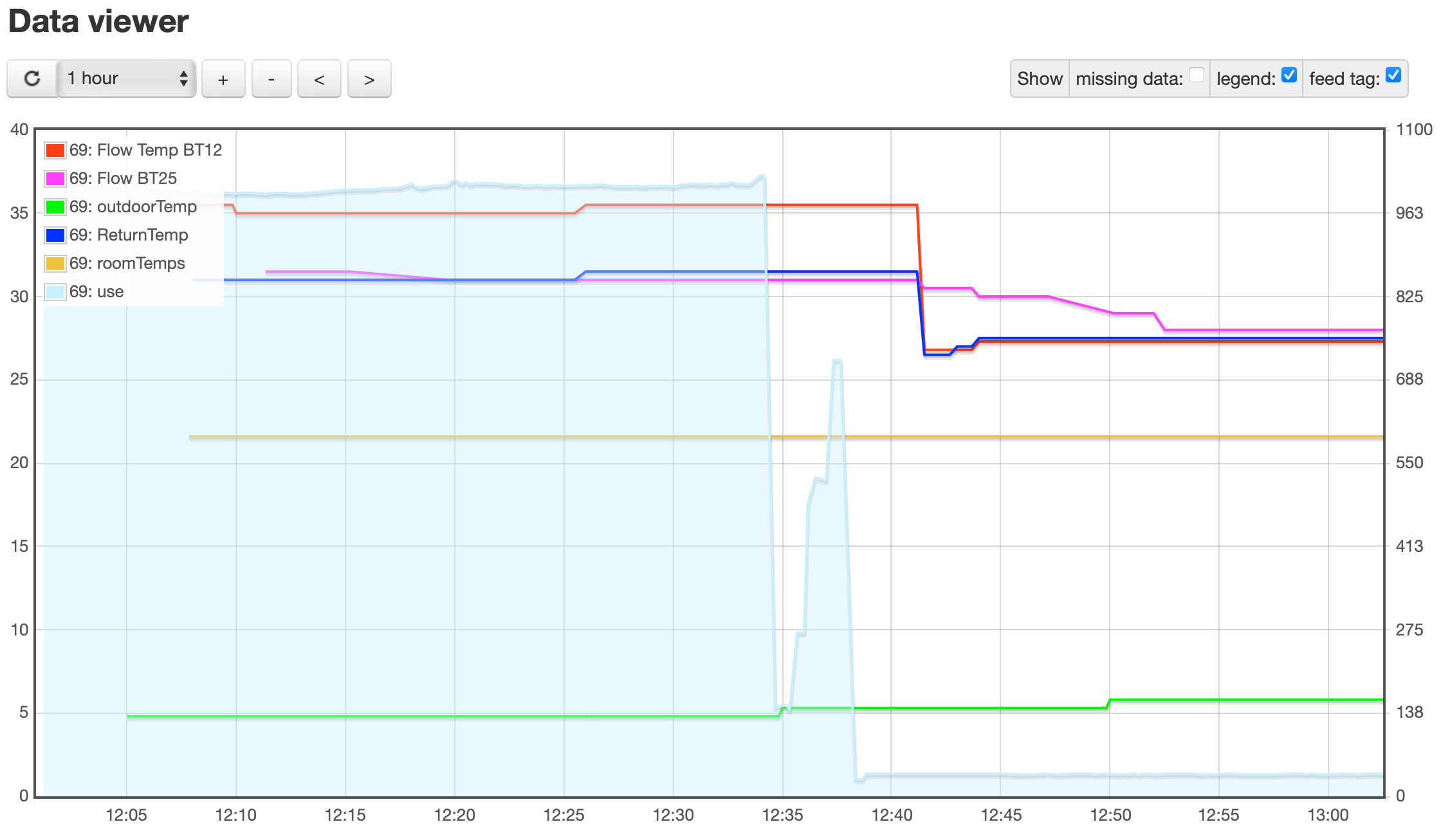
I have turned the radiator pump down and (at the same time) started to reimport BT25 into EmonCMS. There’s not a lot happening just now as no need for heat, but I’ll post an update later:
I don’t believe BT25 is used as part of NIBE’s Weather Compensation algorithm so my judgement is that it’s indicative of an underlying issue rather than a cause or contributor to the problem - so moving the sensor would just tend to mask the issue.
Are you also monitoring the Charge Pump Speed via NIBE Uplink Nick? Would be good to know how ‘hard’ that is working, since increasing that speed might help it being ‘over run’ by the other pumps.
Are you still in contact with the people who designed and installed this system? I’m intrigued by how they expected it to work - especially in terms of the Buffer Tank and the separate pumps feeding the Radiator and UFH circuits.
Thanks David,
Lowering the speed of the maroon/red pump feeding the rads hasn’t seemed to change much by way of deltaT of the (various) flow and returns:
BT25 is still reporting very close to, or below BT3.
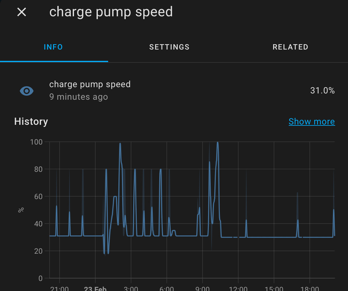
I can monitor charge pump speed, I don’t have it in EmonCMS, but in HA it shows as follows:
I still have the contact details of the firm that put this system in. We are not on great terms as they grumbled about replacing the main fan in the ASHP under warranty, however, knowing what I know now I wouldn’t be surprised if the compressor starts is sky high due to the design of this system…
I saw fairly sustained 50-60 min cycling overnight due to low outdoor temps (-2), which mean my solar batteries were at just 35% when I woke this morning… You should be able to see that on the MyHeatPump app
Where next!? Thanks again for all your support.
Well, the reason I asked about your relationship with the original installer was in case you’d contemplate an element of re-plumbing to implement something more like what I have, with the Buffer Tank plumbed in differently and adding a Low Loss Header. If you do that via a different contractor then the original installer is likely to deny all responsibility moving forwards - but maybe they’re doing that already…
I know there’s a school of thought which says it’s better to avoid the complexity of Buffer Tanks and Low Loss Headers - but you’ve already got a Buffer Tank and multiple pumps feeding multiple emitter circuits, but what you don’t appear to have is the hydraulic separation a Low Loss Header would provide.
The Heat Geek article on Low Loss Headers I linked above says:
Low loss headers are typically used as ‘hydraulic separation’ between any two or more circulating pumps within a heating system. This hydraulic separation allows each pump to work independently at its own flow rates. Without pulling or pushing on the other.
Without some form of hydraulic separation installed, the connected pumps will not be able to run at their own specific flow rate for that zone. This can cause issues like reverse circulation and also unbalanced systems.
An additional problem with two pumps pulling or pushing on one another, particularly with modulating pumps, is that they will interfere with each others feedback response. This can cause an erratic and oscillating/pulsing reaction between one another.
However, I’m in danger of sounding like I know what I’m talking about…
It would be good to understand more about that cycling - were the brief pauses between heating cycles due to defrost cycles (given the outdoor temperature and likely high humidity) or because the Weather Compensation had delivered all its scheduled Degree Minutes?
I don’t get any defrost cycles with my ground source system so I’ve got very little insight into what’s normal for defrosting under different temperature, humidity and heat delivery conditions. Dom’s NIBE ASHP in Manchester might be a good comparison for that.
I think I will write to them and ask them about the logic of this install. Slowing down the rads pump doesn’t appear to have had any affect on BT25.
I started plotting the charge pump speed last night, it doesn’t seem to be doing much either, which, if I understand correctly, probably isn’t helping:
That charge pump speed graph does look a bit odd - I presume the pale blue line is using the right-hand scale?
Running at 30% most of the time isn’t surprising but it’s the fact it only briefly speeds up that seems odd - possibly implying the compressor is only running briefly.
It would be great to see a plot of the Degree Minutes value alongside the Flow/Return temperatures to understand a bit more about how the Weather Compensation logic is working. Are you capturing that already?
Thanks, yes pale blue against right-hand side.
I’ll pull the DMS value through from tonight and post back tomorrow.
Cheers
Good stuff, thanks Nick.
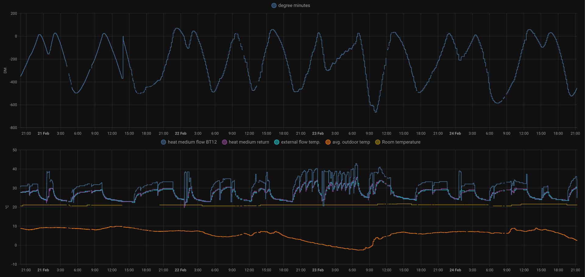
So those short ‘cycles’ around 3am on Feb 23rd aren’t caused by the Weather Compensation logic - that’s still calling for heat (i.e. DMs are negative). Given the outdoor conditions at the time, I presume those are defrost cycles instead.
So overall your system is mostly behaving as I’d expect.
I do have some data on defrosting, i’ll add it in to the mix.
I think the flow is being mixed with the return thanks to the useless buffer…
Would slowing the rad & ufh pump and increasing the charge pump help ensure that rrturn is sent to return and not back through the buffer to cool the flow via BT25?
Me again!
So, it was rather cold last night too and the ASHP was cycling all night. Again, solar batteries down to 30% by 0700 hours which is far from ideal, vast majority of the morning’s energy was used by the ASHP, for heating.
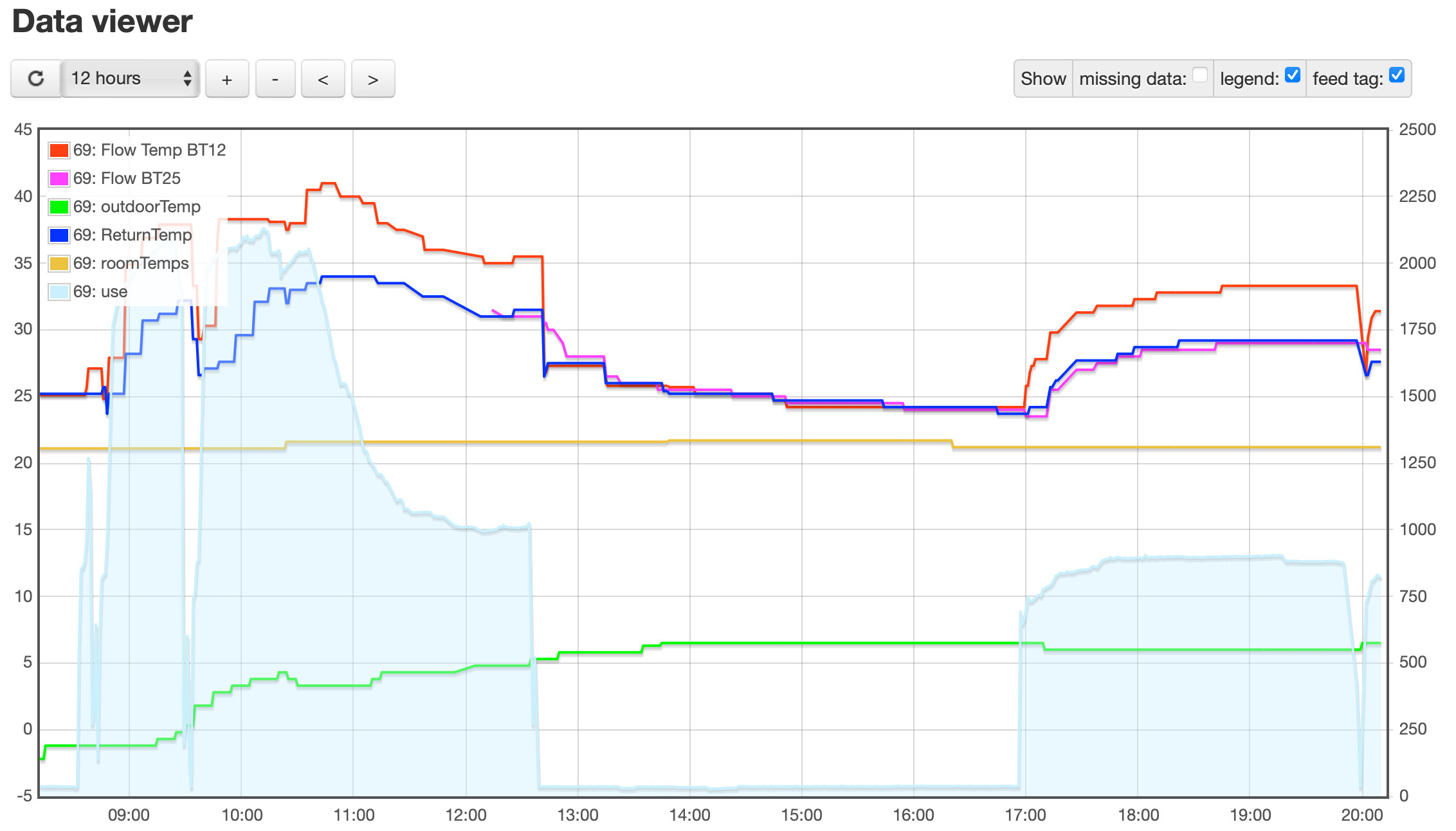
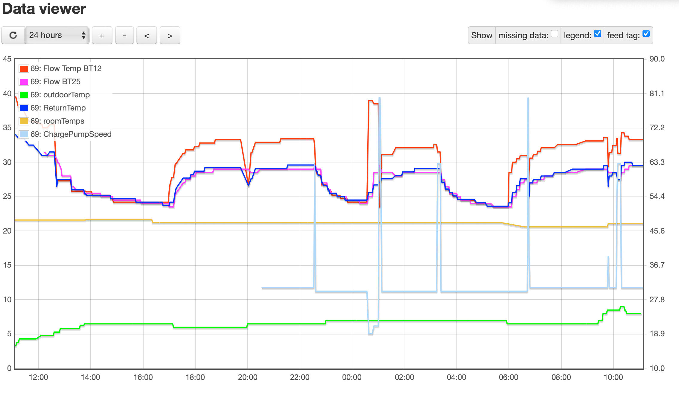
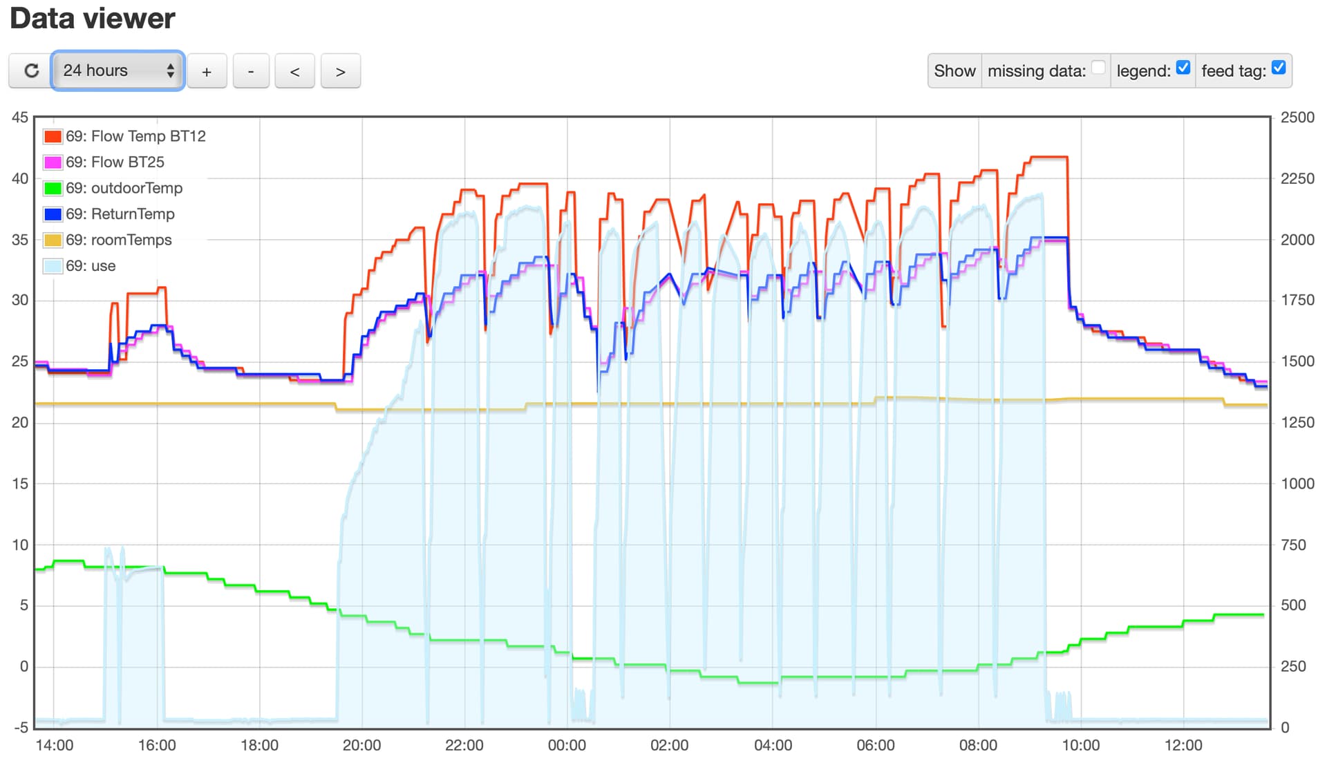
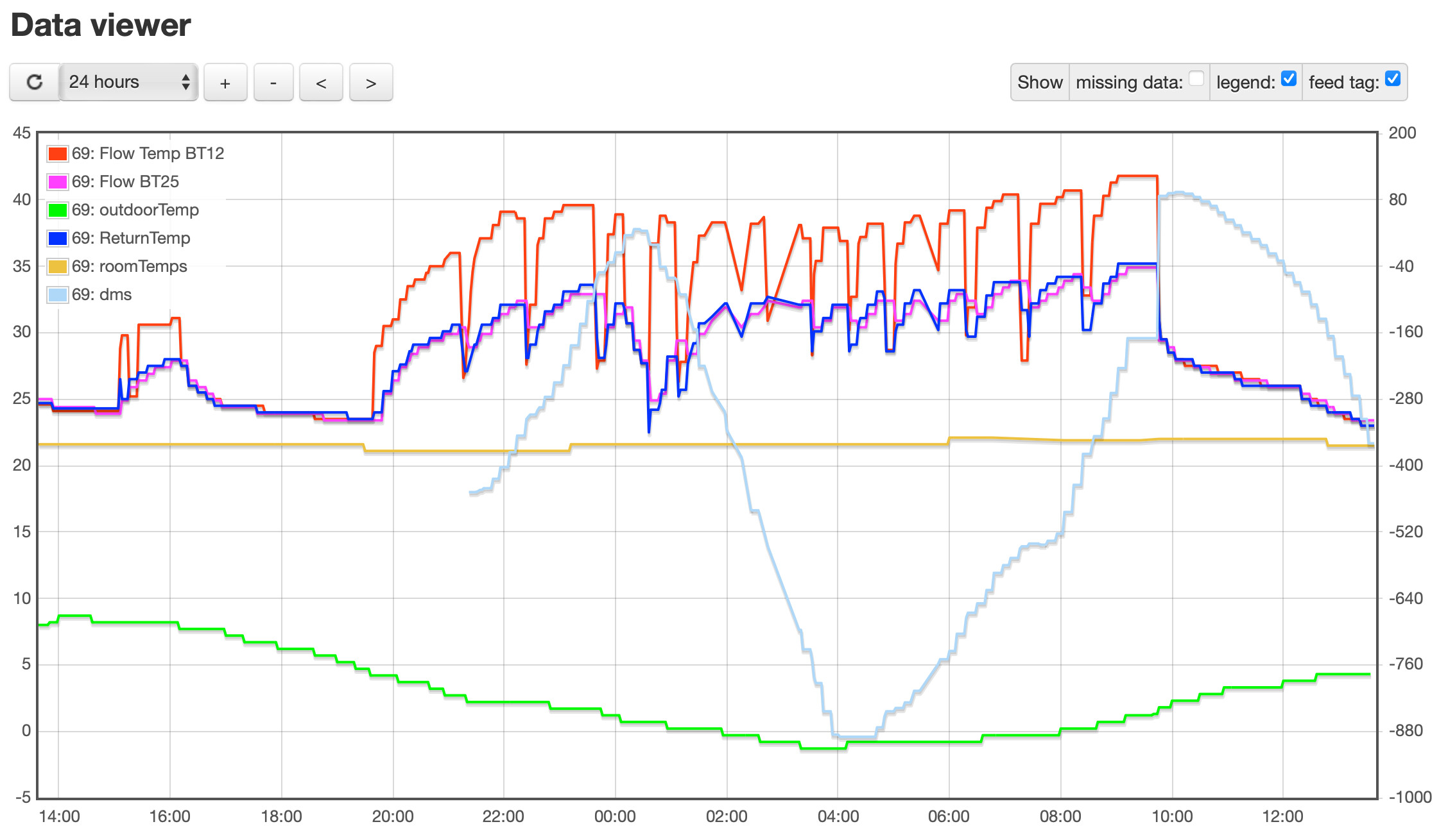
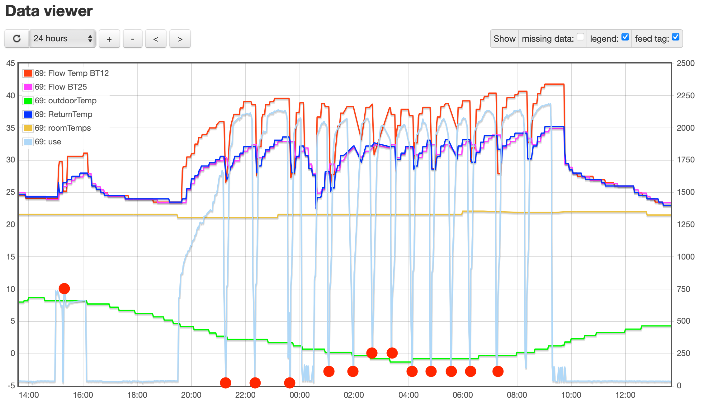
Here are the (dubious) flow and return temps etc against the power used by the ASHP in watts against the right hand scale
In comparison here is the same chart with DMS on the right hand scale:
My assumption here is that there was a demand for heat all night, sub zero outdoor temps and I am also slightly increasing the house temps during off peak period (0030-0430hrs).
However, the defrosting events are:
0105 - 0107hrs,
0158 - 0211hrs,
0242 - 0246hrs,
0321 - 0331hrs,
0410 - 0411hrs,
0449 - 0450hrs,
0538 - 0539hrs,
0616 - 0617hrs,
0714 - 0725hrs.
Here is ASHP energy usage with the defrost events shown as red circles:
There is no denying then that the cycling is due to defrosting. What is interesting is when I got fed up and turned the SMO20 off and on again at about 0910hrs, the cycling stopped altogether, granted the outdoor temp is rising but have seen this before.
Is it then possible that the flow being mixed with return at BT25 is causing the system to work harder than it should to provide the calculated temperature according to the WC curve. The increased workload requires more defrosting events and thus the cycling.
I don’t think the cycling is too much of an issue in the short term, but 2000w over a period of 12 hours does seem excessive.
I am going to email the company that fitted the system on Monday.
I’m really hoping we can find a way for the pumps to limit the amount of return that is drawn in to the flow via the buffer and BT25.
Thanks for sticking with me
Yes definitely looks like defrost cycles. Generally that is pretty normal when outside temps fall below ~4C. In fact around 0-2C (and damp air obvs) is typically when you get most defrost cycling.
I don’t disagree. I feel like I’m still trying to pin down what the issue is, and I’m leaning towards the UFH/Rads temps not getting much above 30, due to the mixing of flow and return.
When the WC curve is calling for >30, typically when outdoor temps are <3, I think this is making the ASHP worker harder >1000w and resulting in more defrost cycles (which isn’t a problem), the problem is the overall energy used to try and achieve an impossible flow temp due to the system design!.. I think!