Hmm, that’s a great write up on the operation of the unit.
All I am really describing is what I see happening. The system gets into a loop that it can’t get out of. There is essentially no DT as the RWT temp has been raised upto the target WL temp.
Setting the pump to 40% stabilises the system and allows it to run for hours. Then gives control back to Samsung after the system is stable.
Seems to work well on my installation. As we know every property and system is different. Running the pump at max does nothing but raise the RWT quickly.
I’ll keep learning and thanks for the detailed description as it helps me to understand why the system is doing what it is doing.
That implies either your sensors are off and are unable to accurately measure the DT or your emitters are not emitting any heat (as there is no DT between emitters and room - i.e, the LWT is the same as the room temp)
It simply makes little thermodynamic sense that water should be pumped around the system and return at the same temp it left.
If you think the sensors may be out, try letting the system stand for 24h and see if both sensors read the same. or try just running the pump(s) with the compressor off and see if both sensors settle to the same reading. If the RWT is reading high compared to the LWT, and you only have a DT of 2-3C, that can soon appear to diminish to nothing. If RWT > LWT, try swapping them, or buy matched pairs and replace (also check they are correctly fitted making good contact)
A couple of observations as a Samsung owner:
Stop chasing DT. The Samsung can run very efficiently with a narrow DT. Mine is only around 3C and the system is achieving COPs in line with the OEM docs.
Until you understand what is happening, simplify things. Fixed rate flow should allow you to see what is happening in the system more easily. Fixed flow rate sufficient to pump the required amount of heat (around 25L/min in my system), and the DT is what it is as heat is dissipated around the system returning lower than it originally left (RWT < LWT).
Setting #2093 = 1 (thermostat only) will allow the system to run without cycling or interference, and if you set the WL low it will eventually reach equilibrium whereby the minimum output matches the heat dissipated by your emitters. LWT will just continue to rise until you reach the point the emitters can fully dissipate the heat being produced. This will give you a good handle on the minimum achievable LWT WL temperature (for my system, this is around 32C, but will be dependent on the size of your emitters). No point setting any lower as you now know it’s unachievable.
Once you have the above basics locked in, you can start making changes and observe the effects. You may want to activate PWM to reduce flow to widen DT, but as @SarahH says above, this can actually be detrimental to overall performance (requiring a higher LWT for the same heat output).
Have you any evidence for this, @MikeJH (assuming that you are referring to compressor stop/starts)? As illustrated below, HP output is high immediately after start-up - quite possibly higher than heat consumption - so LWT may rise quickly to WL target, and could even stop the compressor, especially if the circuit thermal inertia is small.
But in theory circulation rate should make little if any difference to the energy balance - the heat input (from the heat pump) and the heat dissipation (from the emitters) are essentially fixed, and it is the difference between them sets the LWT rise rate, hence cycling propensity.
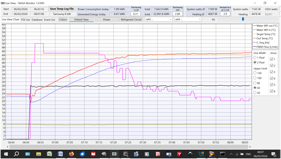
However, by “cycling”, you may be referring to the rather curious compressor inverter frequency variations (magenta line in the following example) in the speed control algorithm as LWT (red line) approaches WL target (yellow line) - a sort of “two steps forward, one step back” strategy:
Just out of interest, the 50Hz speed above corresponds to the Safety Start algorithm which switches to the Normal Operation algorithm about 5 minutes after initial start. Don’t ask me why Samsung wrote the algorithm like that, but I can’t fault the LWT rate of approach and overshoot, so it does seem to work!
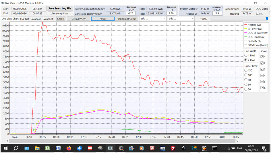
Also, the 50Hz Safety Start does produce a high energy output. Here’s the corresponding energy flow log:
That’s over 10kW (red line) from an 8kW nameplate unit, at a fairly good initial CoP of about 5 (energy consumed is yellow line) though this falls to about 4 once compressor speed has reduced to minimum, due to the proportional increase in parasitic losses.
I was just going on @antonical ’s description of his compressor cycling after start up, due to which he has resorted to an automation to reduce pump speed to 40%. I think your comment was that this should only happen if his emitters were unable to dissipate the minimum heat output of the ASHP. However, that doesn’t seem to be true with his system and occurs at heat outputs above the minimum and appears to be flow related.
Presumably this effect is due to the thermal inertia that you also mentioned.
If the high output for the first 5-10 mins after cold startup is an issue, you can dampen it by turning on Quiet Mode, at least on my Gen6
I do this during summer when I want to try to keep the peak draw within my solar generation rather than drawing from the grid. I typically set a schedule to enable Quite mode before starting a scheduled DHW run, and then turn quiet mode off 10mins into the run once the system is over that initial hump.
I also use #5051 frequency control to limit output, but the system still goes flat out ignoring the #5051 setting for the first 5mins from a cold start, whereas Quiet mode does have an affect during that startup period.
Yeah, what seems to happen is after a standby safety normal sequence the pump runs at max or close to it for a long time. Well beyond 5-10 minutes. The unit spins up the comp to generate the temp needed to get to the Target LWT, RWT starts to climb pretty fast and collapses the DT from below.
All keep telling me the flow rate shouldn’t matter but, of course it does. The Rads need time to transfer the heat into the property to balance the heat loss and gradually raise the internal ambient temp to a comfortable level. If the flwo is raging around the rads do not have the time to do this. Artificially, the system thinks its job is done, result cold rads and house. Constant cycling.
The entire installation was tuned to a DT of 5 and all rads balanced. When we clunkily temper the flow rate to ~15 LPM the system stabilises, the rads are now warm (at these temps never hot) and the property starts to get up to temp. Handover control back to Samsung and it runs pretty much how we expected it to run. Low and slow, house feels great no complaints etc.
I am sure I can make my automation more sophisticated just not had time to investigate using the NASA connection further.
Hmm setting #2031 (LWT target temp) to 1 - if you can (the minimum is 17) - might have some interesting consequences . I presume that you meant #2091 (or else this was a late April Fool’s ).
Still struggling to find the registers for WL. Also can’t find the ‘offset’ register either.
Right now we have a settign that seems to work adjusted with an offset of -2 for overnight and +1 or +2 depending how cold it is outside.
I really want to automate all of this using HA but can’t find the registers. Ideally, just the offset register would be perfect as I would just have one write to set the required offset depending on the TOD and temp.
It may not be there to be found, @antonical. Even on older series Samsungs, it doesn’t show up in the NASA traffic on F1/F2. I haven’t tried looking at F3/F4, though the WRC - which does show the offset at least on non-integrated units - looks there all the time of course.
I surmise that the controller creates internal alternate registers for #2021/2 based on the FRC offset value and uses these rather than the true #2021/2 registers for WL target calculations. (At least that’s what I would do if I was a controller programmer which, happily for other Samsung owners, I definitely am not ).
So you may have no option but to manipulate FSV#2021/2 from HA. This is dead easy on Gen6/HTQ series of course (see above posts) but maybe not on a Gen7.
(You may have more luck if you ditch Modbus/MIM-B19N altogether in favour of simple NASA via F1/F2. Without first hand Gen7 experience I can’t guarantee success, but I’d definitely give it a try, particularly if you already have the RS485-Ethernet adapter to hand.)
Many thanks. Yes I have both a Modbus and F1/F2 NASA connection. I also tried spinning up a Win 11 VM and trying to install the SNET Pro software but it seems to want an ancient .net version which even when installed does not work.
Have you considered throwing in the towel and installing a secondhand windows-based laptop just dedicated to SNET? At least it would let you explore NASA much more easily…
How does that help. I have installed a new windows machine the fact it is a vm is irrelevant. We use hundreds of them. It has networking etc. What I can’t seem to install is the SNET Pro app as it is stuck in a loop on an ancient .net 2 req. Which even when installed it does not recognise. This software must be ancient!
And what if any files do you see after you have unzipped the download? (On a native Windows machine you would get a C:\Program Files (x86)\SNET pro2 folder.)
Depends on whether you have an F1/F2 sniffer. Assuming you have, you can for example write to F1/F2 using SNET (e.g. FSV changes) and watch the NASA traffic using your sniffer (Request and Acknowledge packets). That is, you can map FSV numbers to NASA registers. This mapping is already well documented for pre-Gen7 Samsung controllers, but from what you have reported above and elsewhere, it sounds like the MIM-E03FN (or whatever Gen7 uses) has a different mapping.
I recall giving a bit more background to NASA packet construction in Samsung ASHPs: Customising Your SNET-Pro2 Display. It’s probably too simplistic for you, but it might pay you to have a quick read of it if you do manage to fire up SNET.
Many thanks for this. I believe we got the latest from the Samsung partnerhub portal as we registered for a Samsung Climate Solutions Partner Account. Having just looked the latest version on there is 1.13.9. I ahve requested the latest version and any installation advice for windows 11.
I am going to have another go at this on a totally clean new win vm no other .net versions installed.