Monitoring EV charging - newbie question

I have a new (but dumb) EVSE in the garage and want to be able to monitor & record the amount of kWh used by the EV. I’d also like to monitor usage of the other things in the garage (freezer, heater etc).

Would a two clamp emonPi suit? Or should I be looking at some other solution? I have wifi in the garage. I can envisage putting one clamp on the EVSE cable, and the other on the cable coming in to the garage - and then manually subtracting one from the other. Perhaps a bit of a kludge, but I need to work with the way the cabling has been done.

The house (& solar panels, but NOT the garage) are monitored by an intuition OWL system which I really don’t want to change. I also do NOT want to change the EVSE - sorry!

TIA

W Sussex, UK

Hello Julian. Welcome to the OEM forum.

I presume you’re talking about a current transformer when you write “clamp”.

The setup you envisage is essentially exactly what the emonPi was designed for - one incoming power feed and one other branch off it, except that it was designed for PV feeding power in whereas in your case it is the EV consuming power.

You don’t need to be

you can do that sum on the inputs page of emonCMS so that you have total garage power (CT1 say), EVSE power (CT2 say), Garage Power(CT1-CT2).

I’m guessing you have a consumer unit in there and the EVSE is on a MCB in that. What you’re doing is OK, but because you could be subtracting two almost equal numbers, you might find some strange values for the freezer and other loads, due to small inaccuracies arising from component tolerances. (The good news is with care, you can probably largely calibrate those out.)

I don’t know what Owl does or is capable of - but if it can send its data somewhere, you can probably import that into emonCMS and integrate the two lots of numbers.

From what I can tell, it’s an apparent power type of monitoring device.
The docs for all of the devices on their website say both the sensor and the display are battery powered, i.e. I couldn’t find anything that made use of an AC voltage sample.

Here’s one of their manuals:
Getting started with Intuition-e v3.0.pdf (401.6 KB)

I seemed to remember looking once and decided that too (and guessed apparent power, based on the nominal voltage) but didn’t remember whether there was any sort of output other than a display.

Here’s some more info:

I’d say the part about a fixed voltage set in the display fairly well ties it, wouldn’t you?

That pretty much implies guessed apparent power, based on the nominal voltage. So it will be accurate when the voltage and power factor together happen to give you the right answer. :anguished:

Many thanks both - for your welcome and Your help!

You will need to forgive me in places as I am not an electrical engineer, but I am reasonably practical. I had never made the distinction re: apparent and true consumption before, but the Owl does utilise a power factor and so the results can be inaccurate / fudged to suit. But over time one can adjust the PF to make it agree with the mains and PV meters & so it has been fine for my needs. But perhaps now would be as good a time as any to swap over to a more accurate & capable set up…

The wiring in the house & garage has grown organically as needs have changed, but I have

I have attached a simplified diagram of what I have. [EDIT New users can’t upload attachments, so have uploaded it to Dropbox at Dropbox - File Deleted ] The garage is ~50m from the house and they are connected by two large armoured cables (with 10mm2 wires within). The use of these two cables has recently changed, but now but least it does give a high power delivery to the garage for as and when we get a second EV. Both the house & garage have good wifi.

At the moment, I have Owl CT clamps between the mains meter and both CU1 & CU2, and also between the solar meter and CU4. This enables me to measure household consumption, solar panel production, & power export to the grid. But NOT general garage consumption. This was fine until my new EV car arrives…

Does anyone have any suggestions as to how an emonPi might fit in to this system? Ideally I’d like to monitor / record the following …

a) House (& garage) general consumption
b) EVSE consumption
c) Solar panel production
d) Amount of power exported to the grid (in real time)

The last line is important, as it helps us to know when to turn on things like a dishwasher / washing machine. This does require a companion iOS app.

If all of this is just too complicated I won’t be offended in the least!

[EDITED TO ADD: The Owl CT clamps connect to their base station through their own wireless connection (not wifi); it looks as though the emon CT clamps need to be hardwired which would create an issue for me vis. the two buildings :fearful:]

TIA

Julian
W Sussex, UK

Please copy it here - I’ve upped your permissions, you should be able to now. I’ll take a look at what you have then.

2019-07-13 OWL layout.pdf (316.7 KB)

I think your house needs an emonTx with the ESP8266 Wi-Fi add-on (https://shop.openenergymonitor.com/esp8266-wifi-adapter-for-emontx/).

That will give you 3 × 100 A c.t. + 1 × 16 A c.t. I’m not sure what you could use the last one for (it is relatively easily changed to a 4th 100 A input or somewhere in between if you can solder on a p.c.b), but the others can go on the mains incomer (giving you nett grid power) and the two house C.U’s.
The data will go via your LAN into the emonPi in the garage, then back to your phone/laptop/tablet or whatever you want to use to show the data.
If the emonPi in the garage reads the PV and EVSE, then it looks as if you’ve got all the main loads except the garage lighting and freezer measured directly. You deduce that because “C.U.4 lighting” = grid - everything else.

Unless you’re deeply into electrical engineering and energy, that’s not surprising. Many people know “Amps × Volts = Watts” - but don’t know that it’s only true for well-behaved things like electric fires and kettles. For “awkward” things like laptop power packs and central heating pumps, its “Amps × Volts > Watts”, so if that’s the sum your OWL does, it gets it wrong most of the time one way or the other, but the errors average out over time.

Thanks Robert; I’ve drawn up a revised sketch which shows what I think you have described. Do you think it might work?

2019-07-13 emonPi layout.pdf (477.3 KB)

Can one readily access the utilisation of each clamp individually, as I would ideally like to know what the EVSE uses in itself.

I am still unclear about how the Solar PV bundle works with its’ clamps etc, but perhaps the “shop” can provide more info when they return from vacation?

At the risk of getting ahead of myself, how does this sound for an initial shopping list …

x1 emonPi - Solar PV bundle
x1 emonTx (currently out of stock)
x1 ESP8266 wifi
x1 optical pulse sensor
x5 CT clamps
x1 AC voltage sensor
x3 power supplies
x? Emoncms.org credits

TIA

Julian

I was going to do it the other way round, and put the emonPi in the garage. But what you have will work, you just won’t be able to have a direct reading of the nett grid power. That’s why I put the emonTx in the house, and the emonPi in the garage.

Arising from that: What do you want the pulse sensor for?

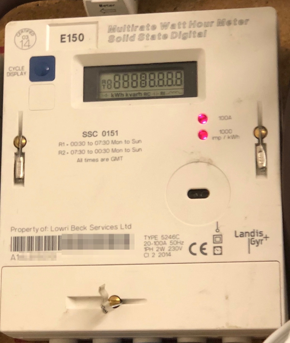
If it’s for your grid meter, here’s an awkward question for you: Does it pulse both when you are importing and exporting, and if it does, how can you tell which it is from the pulse? My bet is it pulses only when importing, so when you have PV (unless you want it for calibrating the c.t’s), it’s of limited use. Some meters pulse both when importing and exporting, but you still can’t tell whether the pulse applies to import or export.

I think you’ve over-ordered in places.

x1 emonPi - Solar PV bundle includes 2 c.t’s, it can optionally include the a.c adapter and 5 V d.c psu and pulse sensor.
x1 emonTx (currently out of stock)
x1 ESP8266 wifi
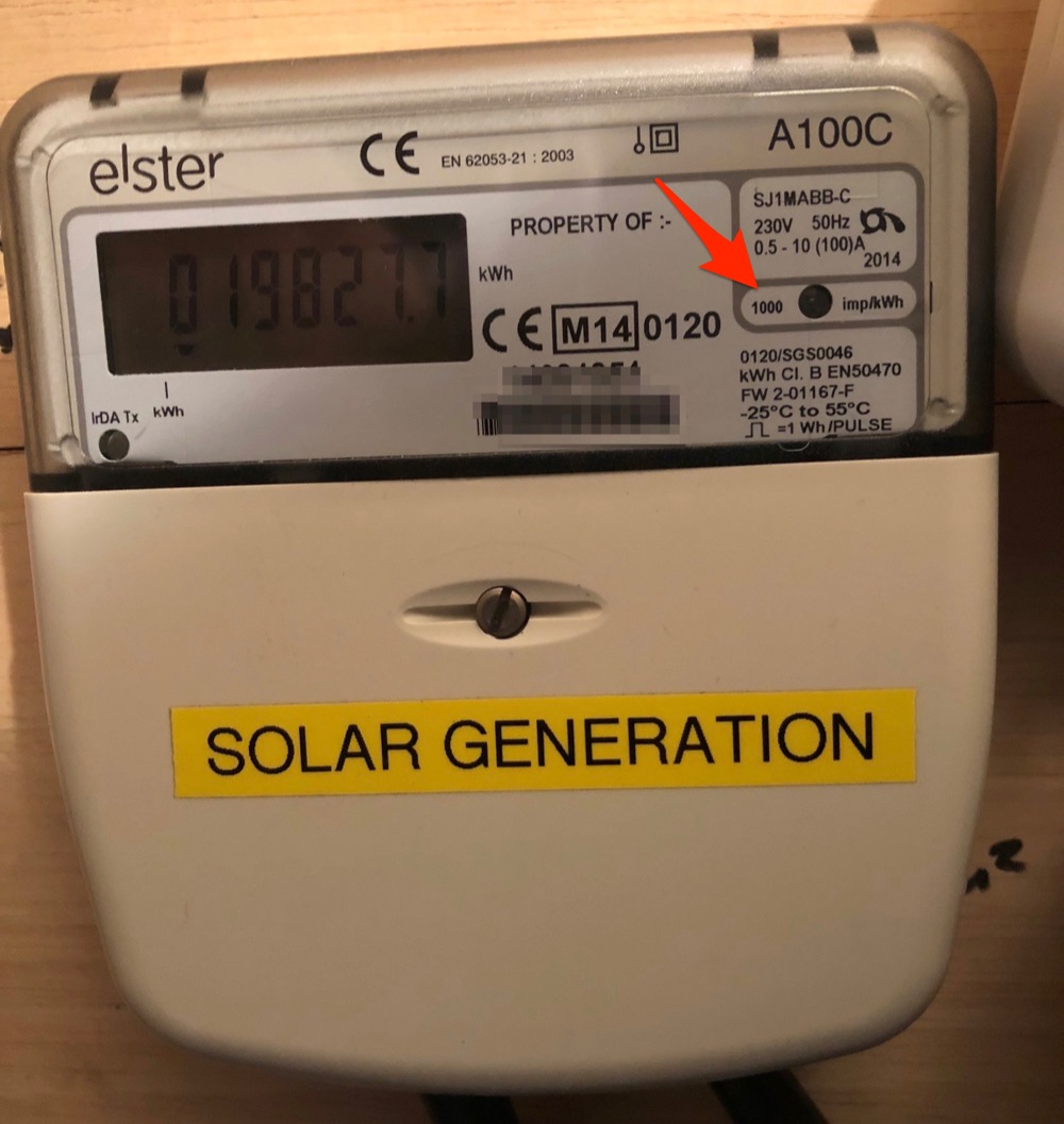
x1 optical pulse sensor You can have this in the Solar bundle
x3 CT clamps You already have 2 in the Solar bundle
x1 AC voltage sensor You want 2 in total - 1 in the PV bundle plus this for the emonTx
x1 power supplies You need 2 - 1 in the PV bundle plus this for the emonTx - the a.c. adapter can only supply enough current for the emonTx, not the ESP8266 as well
x? Emoncms.org credits Why? - you have emonCMS on your emonPi - free for evermore. You can send the data to both - and then the two versions both have to be set up individually, and because the two versions are not exactly the same, it’s a recipe for confusion until you get familiar with both.

In emonCMS, each input - be it the voltage, power¹ or pulse count, appears individually. You can then do various processing on them, e.g. adding CU1 + CU2 to get the house total, and then you “Save to feed”. A feed is where the data is stored. You can send the data to a (different) feed anywhere in the input processing, so a feed can be the raw data, it can be two powers summed, it can be power integrated over time to give kWh, etc.

¹ Both the emonTx and emonPi report only voltage and real power² by default. You can edit the sketch and change that to show current, apparent power, power factor instead or as well if you wish.
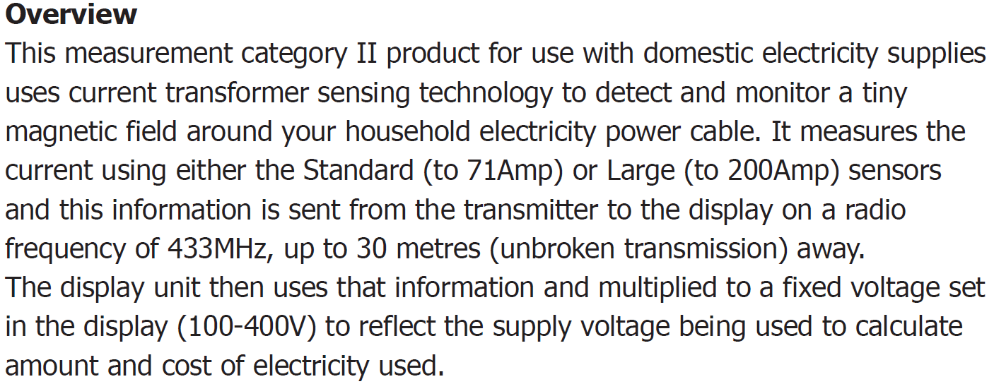
² Real power if there’s an a.c. adapter connected, otherwise nominal apparent power - like your OWL.

Answering some of your points …

I put the emonPi in the house as the garage “needs” 3 clamps & thought that the emonPi could only have 2. But happy with your suggestion, and have updated the sketch as I now realise the Solar PV box comes with its own clamp.[EDITED TO ADD: I may well have got this wrong - the solar PV bit is just software, so I’ll be a clamp connection short?]

2019-07-13 emonPi layout v2.pdf (463.2 KB)

I sort of took from earlier comments that a pulse sensor was preferred in order to get a more accurate power consumption, but if not then that is fine also. I did check the lights on the meter, and when I am importing the lower light flashes (top light is off), but when exporting both lights are on solid, so maybe it is academic anyway?

As an aside, I had the meter fitted a few weeks ago in readiness for the new EV car & probable switch to Economy 7 but I now see the time displayed on the meter is wrong - at 19:17 GMT last night the clock showed 18:54 GMT. Very strange!

Thanks for the comments re: what to order. And good news re: the emoncms.org being superfluous. And I now understand how inputs can be grouped in to feeds - sounds perfect.

Julian

The emonPi has only two c.t. inputs. The “Solar PV bundle” IS the emonPi along with various optional and non-optional accessories - and you don’t want two emonPi’s. What I think I would do - but it’s for you to weigh up the advantages and disadvantage - as option 1 is put the emonPi in the garage with CT1 on the EV and CT2 on the PV infeed; put the emonTx in the house with CT1 on the grid connection (if you can get at it), CT2 and CT3 on the two house CU’s. The disadvantage here is the only way to get at the garage miscellaneous load is it’s grid minus everything else (and that will contain all the errors of all the measurements).

Option2 might be difficult or impossible, depending on whether you can get both the house CU feeds through one c.t. If you can, and it’s acceptable to sum them in the c.t. itself, you can put the emonPi in the house with CT1 on the grid connection and CT2 on the two house CU’s.; put the emonTx in the garage using 3 c.t’s on EV, PV infeed and CU5.
I’m putting both these forward with a c.t. on the grid infeed as I feel it’s important to measure that rather than deduce it from the sum of all the other readings.

But if you feel that you can reconcile the calculated sum with the manual meter reading and that will be acceptable, then what you had earlier (2019-07-13 emonPi layout.pdf) is what you want.

That means you can only use the pulse count as a measure of imported energy, not the nett energy (clearly, no flash when exporting = no knowledge of the quantity of exported energy).
If you do have the pulse count, you should find it will have the same slope as the grid energy when importing, but when exporting, it will freeze on the last value while the grid energy goes down.

One more possibility, if your Solar meter has a pulse output: put the optical sensor on that. We know all PV inverters consume overnight - usually it’s about 10 - 20 W, but that’s on the bottom end of accuracy for the emonPi anyway. If that ‘leakage’ is an acceptable error, then you go with your last proposal except that you have the emonPi’s c.t’s on the EV and CU5, and the pulse input on the PV infeed.

The pulse count by definition is an accurate measure of energy that has been consumed. Note the careful choice of words - it doesn’t necessarily give you an accurate measure of power, particularly at low powers, because you only get a pulse after you have consumed one quantum of energy - 1 Wh in your case, whereas a c.t. will give you a measure (of current, from which you calculate power) whenever you ask it. And that may well be several times between one pulse and the next. But at high powers, then that problem goes away - if you’re charging your EV at 10 kW, you’ll get 10 k pulses per hour - a bit less than 3 per second, 28 over the standard 10 s reporting period, and that puts it into perspective.

That has all been very helpful - thank you. The solar meter does have a pulse window (& was flashing just now during a period of production). So I could put the emonPi in the garage with a CT clamp on the EVSE and another on CU#5, along with a pulse sensor on the Solar Meter.

In the house I could put a CT clamp on the wire between the Dual Rate Meter & the Junction Box, but not on “only” the wires to CU#1 and CU#2 combined. But perhaps putting a CT clamp on each of the wires to CU#1 & CU#2 individually would be OK. (I’m not trying to get huge accuracy here - it is more for general interest than minutiae).

2019-07-14 emonPi layout v2.2.pdf (581.5 KB)

Thus,

  • adding the “inputs 1,2 & 4” I can get a “feed” showing total non EVSE consumption
  • adding the “inputs 1,2,3 & 4” I can get a “feed” showing total consumption
  • “input 3” gives EVSE usage
  • the “pulse input” gives solar production

From this I can (presumably?) display in real time through emoncms a) combined usage, b) solar production, and c) net import/export of power from/to the grid.

Is there any important differences between a CT input & a pulse input - other than perhaps a slight delay in pulse data during low consumption periods?

You can put a c.t. on either side of the meter - it doesn’t matter very much on which cable it goes, line or neutral, supply side or load side. You just point it the other way if it’s on a neutral.

Your sums look OK.

Yes, you should be able to do that.

The obvious one: the CT input gives you power, the pulse input give you energy. Integrate over time or differentiate with respect to time to get from one to the other. It’s the differentiation step that creates problems in the world of discrete pulses because emonCMS (and it’s not in the cloud, it lives on your emonPi) uses a fixed time interval so power from pulses comes in steps and delayed, rather than just delayed, and will be zero if there isn’t a pulse during the last 5 s. Let’s say there is one pulse every 15 s. At the first 5-second ‘tick’ after a pulse, it will calculate the power on the basis of 1 energy quantum per 5 s. Then it will report zero twice running, then a power again 15 s later. This is a bit problematical.

You have built-in functions to do the conversion - but I’m not an emonCMS expert and I haven’t got an emonPi running at present so I can’t tell you what they are nor their exact usage.

Thanks again;

  1. Swapping the emonPi to the House (c/w x2 CT clamps), and the emonTX + ESP8266 (c/w x3 CT clamps) to the garage would obviate the need for a pulse monitor, and would therefore keep all sensor types the same. Perhaps this would be a simpler / neater solution. Or would this break the “solarPV” aspect of the system (vis. the solar PV clamp not connecting directly to the emonPi)?
  2. Noted re: no cloud WRT emonCMS; I will study how it works in more detail later, and read through the how-to-backup-data page thoroughly.

2019-07-14 emonPi layout v2.3.pdf (573.9 KB)

If you don’t want a direct measure of nett grid power, that’s fine.

I think you’ve got a bit of a misunderstanding regarding the “Solar PV Bundle”. Forget it - it is just a list of standard components, there’s nothing special about it.

Think of it this way, and it’s not far from accurate:
An emonTx is a 4-input power measurement box that sends the data somewhere.
An emonPi is a 2-input version of the same and it’s got a Raspberry Pi inside the box as well, which runs emonCMS to store and analyse the data. Both need an a.c. adapter and c.t’s to measure power. Both can accept a pulse input to measure energy. And with an ESP8266 added to the emonTx to give it WiFi, both have Wi-Fi and both need a 5 V d.c. USB power supply. The emonPi has wired Ethernet as well as WiFi.

EmonCMS has pre-configured pages that assume a standard ‘solar’ setup - your setup is different so you’ll need help from an emonCMS expert if you want to set your emonCMS up to use those pages. But you don’t have to use them.

[And I do wish you’d stop calling c.t’s “clamps”. As far as I can tell, it’s a bad Chinese translation. I’ve known the component as a current transformer for the last 50 years, and I won’t change any time soon. The standard ones we use have a very brittle ferrite core. If you clamp or wedge that on a cable, you may well fracture the core and then the c.t. is useless.]

Sorry for the misdescribing of the CTs - I had not realised I had been wrong.

Understood that I can look on both the emonTx and the emonPi as [2/4] input measurement boxes, and with the addition of the ESP8266 both emonTx & emonPi can talk to each other. What I am not clear about though is, other than the different number of inputs, does it matter which box goes in which building?

I’m almost there - and conscious that I have already taken up a lot of your time - but I remain very grateful for your help!

In your case, no - because you aren’t using the built-in 433 MHz radio link and because you have WiFi in the garage. Had you not had Wi-Fi in the garage and were using the radio, then obviously you’d need the emonPi where there is either a Wi-Fi or a wired Ethernet connection to your LAN.