Ill go back next week and refit the temperature probes. Is it likely then that the prinary pump is undersized? I noted that Tims has twice the head.
I reckon the pump is just about big enough to pull in the amount of heat the property needs, as the heat pump is oversized. Might start to struggle in prolonged sub-zero weather.
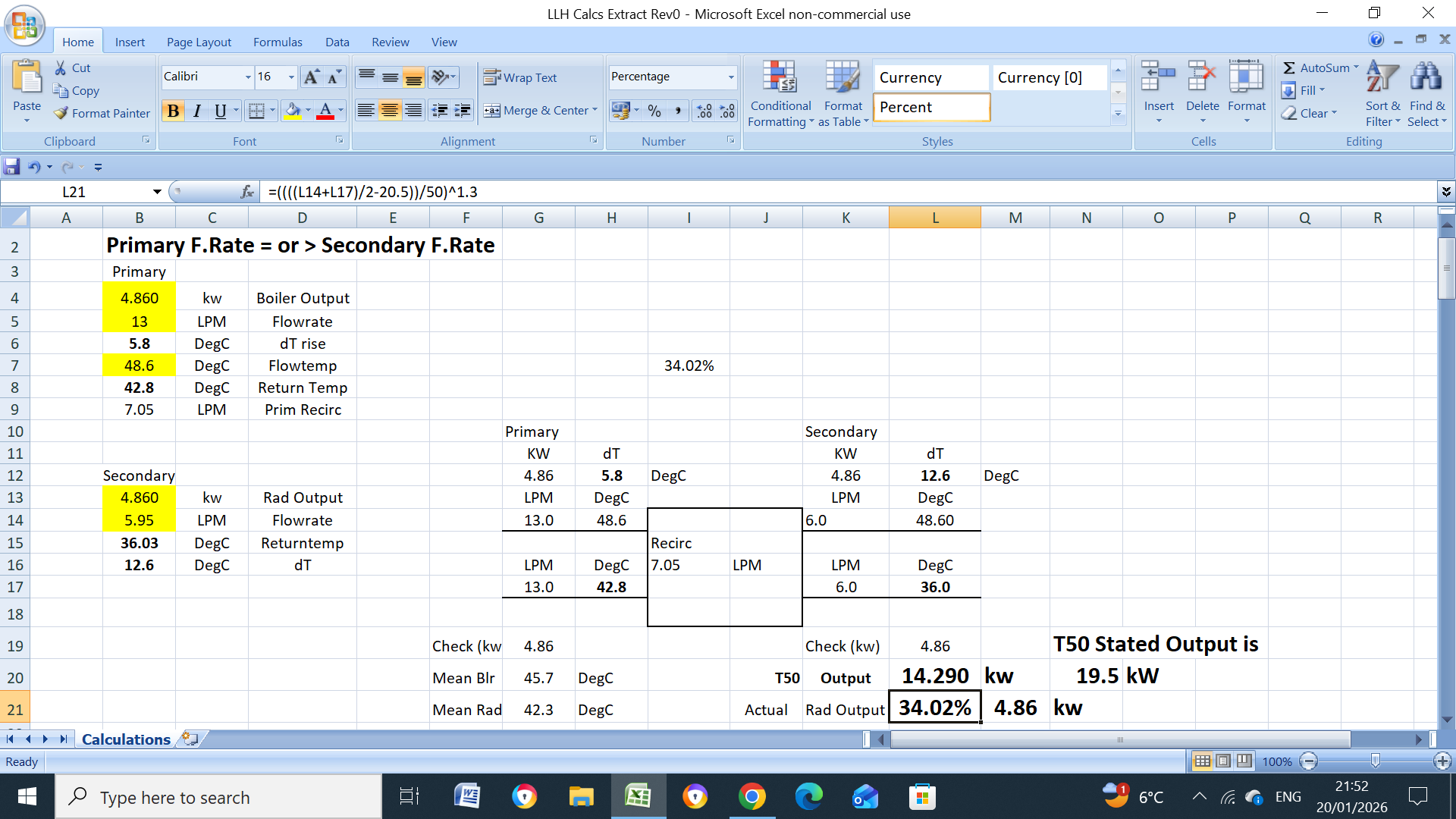
This seems quite low. The radiator output (at that point in time) was less than 15% of it’s rated output. When I checked my temps a couple years ago, I was seeing broadly the same mean and dT values across the radiators as was coming out the heat pump.
An experiment to try: open the lock shields by a 1/4 or 1/2 turn on every radiator - see what happens to main flow temps.
Will do. The low temp at the rads has to be due to:
1 pipe restriction
2 heat loss in floor slab
3 uneven flows in the LLH
4 any other ideas???
I went to site today, checked the thermal probe positions against the pipework and reseated them with ties, thermal paste and Al foil over the top. I also measured the DTs across all the radiators, which varied from about 5C to 1.5C. Some of the lowest ones were fully open.
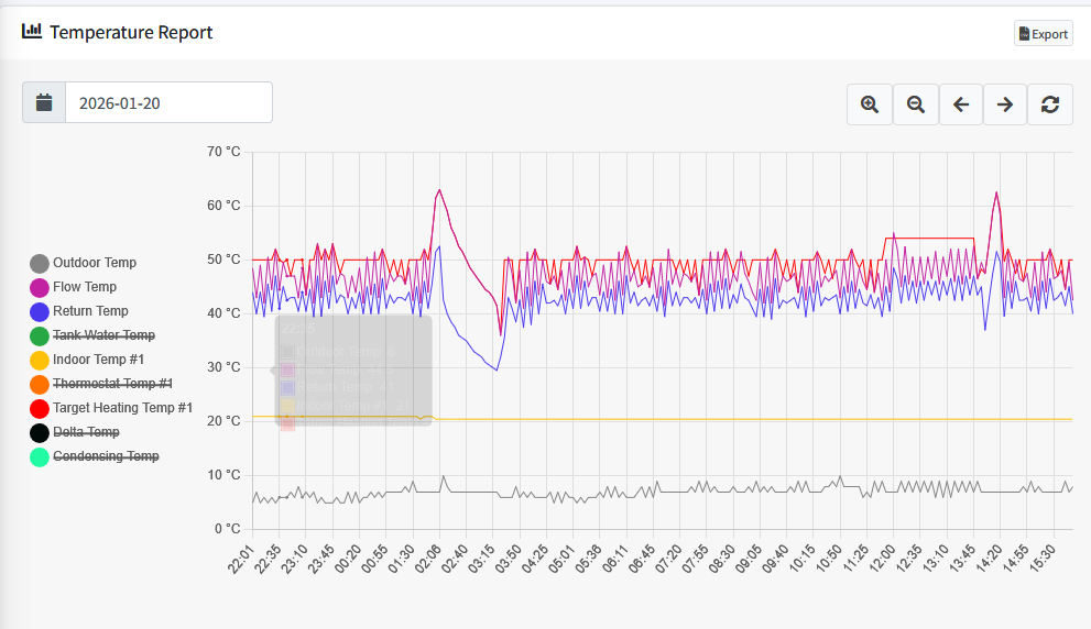
The HP was oscillating again so I switched to constant flow temp and got this
The system still wouldnt stabilise but I did get some movement on the secondary side temperature.

I then switched back to Auto Adapt and noticed something new
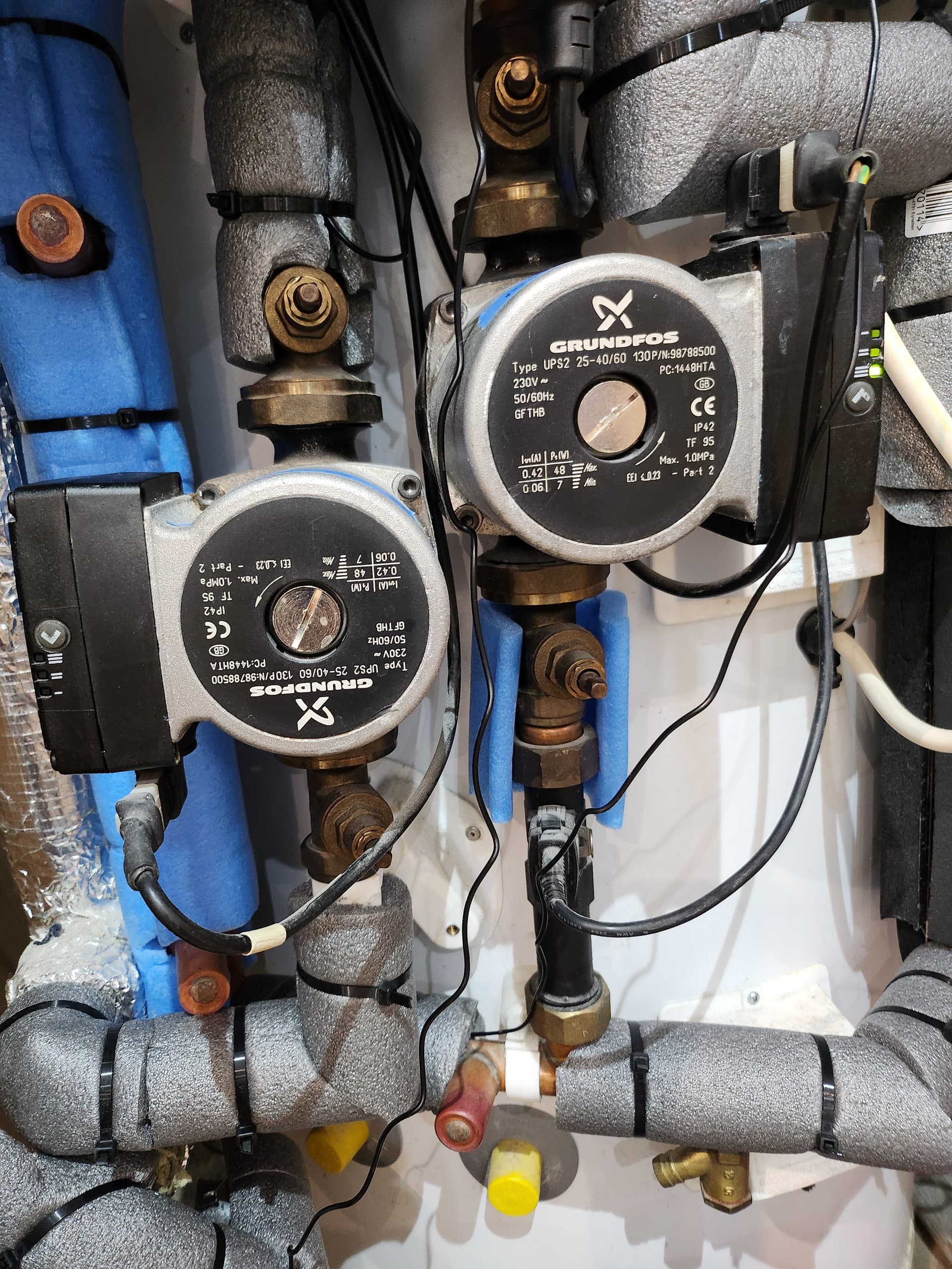
The light on the secondary pump had gone out. Does using AA mean the pump is controlled by PWM? The reading at that point were as below
Im currently waiting for the system to stabilise so i can ring and ask them to take a picture.
No. The speed of the secondary pump is fixed, and turned on when in unit is in heating mode.
The light on the pump went out in your second picture, before switching to AA mode - looks like it may have been heating DHW at that point.
I have never seen Grundfos Auto Adapt working “properly” in any situation where I tried it, anhow, I think CC or CP are the appropriate modes with a LLH.
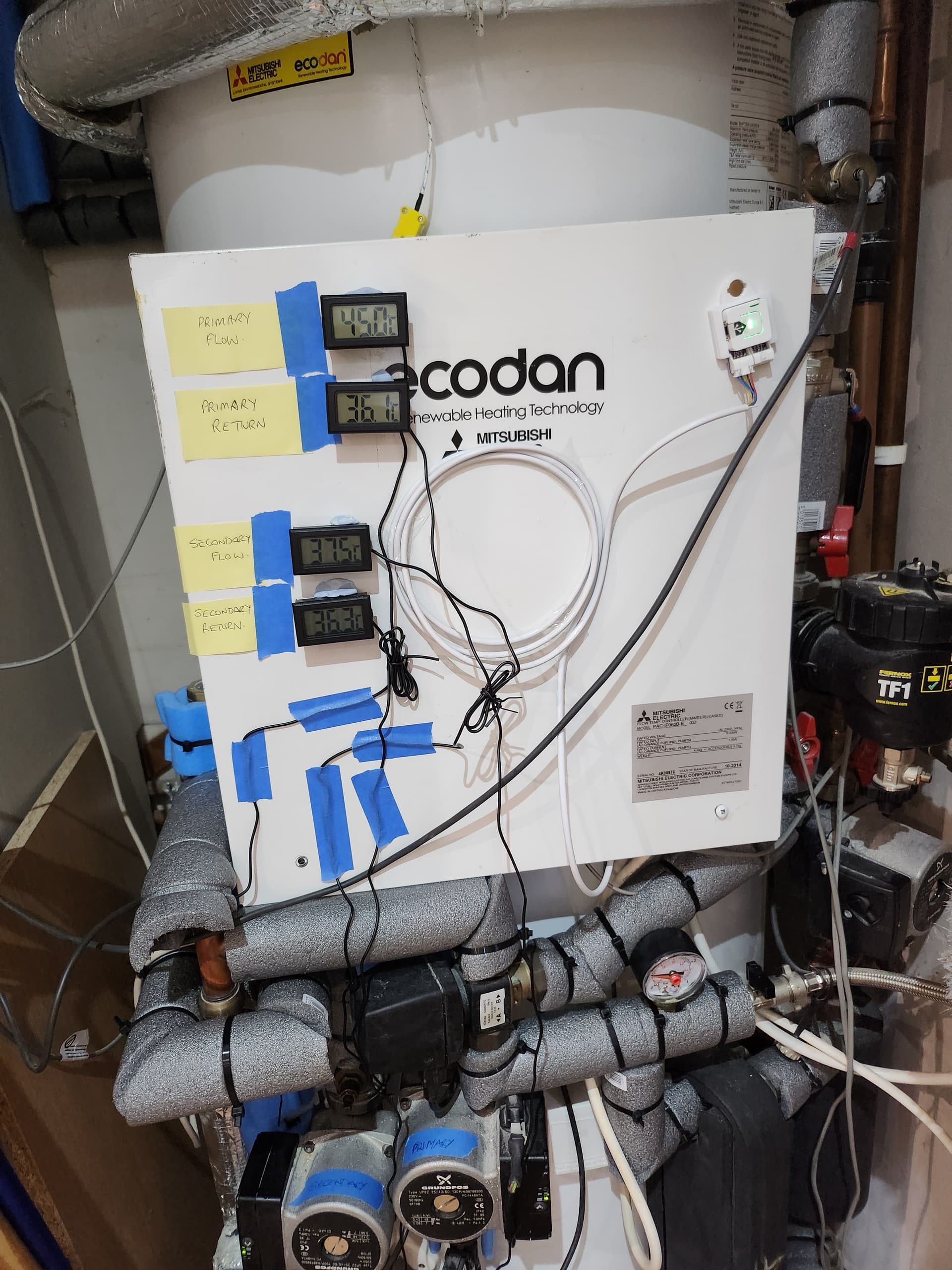
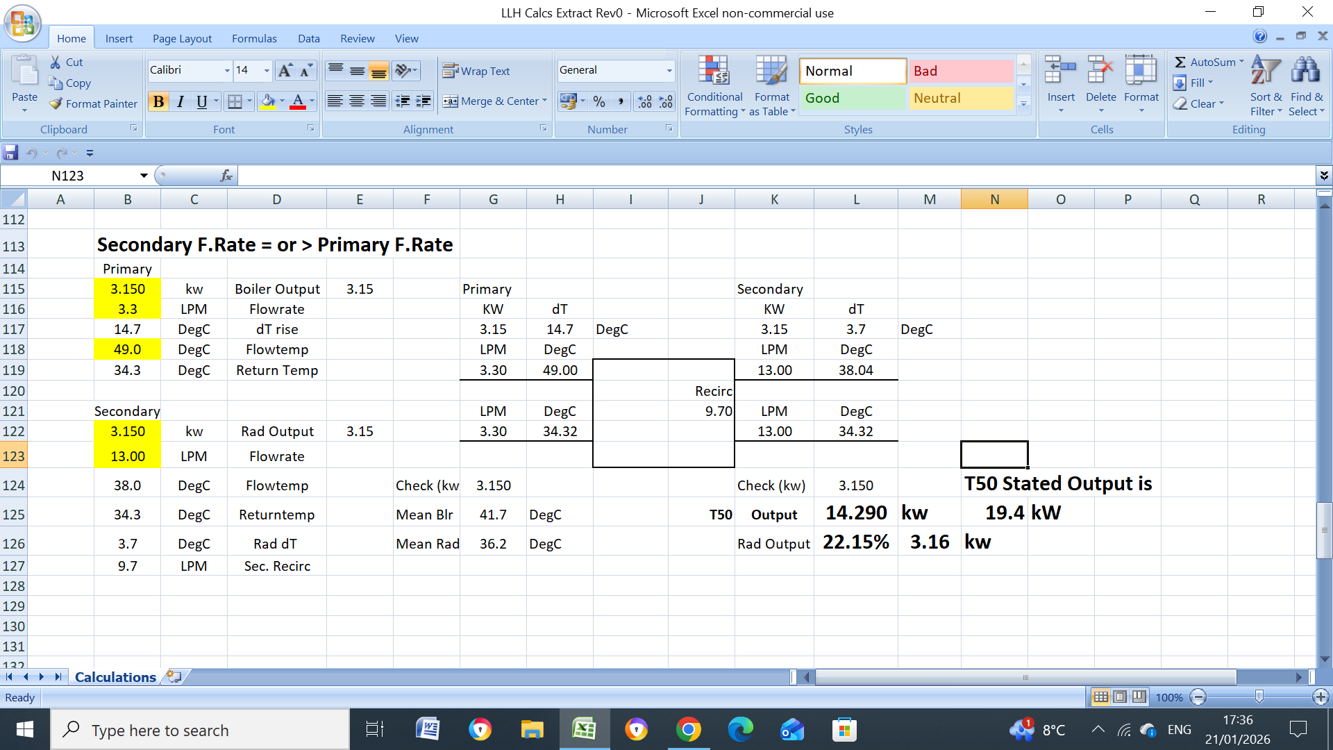
Before?? you tried AA, Your readings…Prim 48.6C/44.0C/dT4.6C. Sec 46.7C/36.0C/dT10.7 Mine Prim 48.6C/42.5C/dT5.8C/13.0LPM SEC 48.6C/36C/dT12.6C/5.95LPM HP Output 4.86kW Can’t make any sense out of the second set of readings but will have another look.
That explains it. I didnt think I had seen it before. Btw I did open the lockshield valves and a couple of rads that had a low DT
I think its hard to make any sense of the readings until it settles in a stable position.
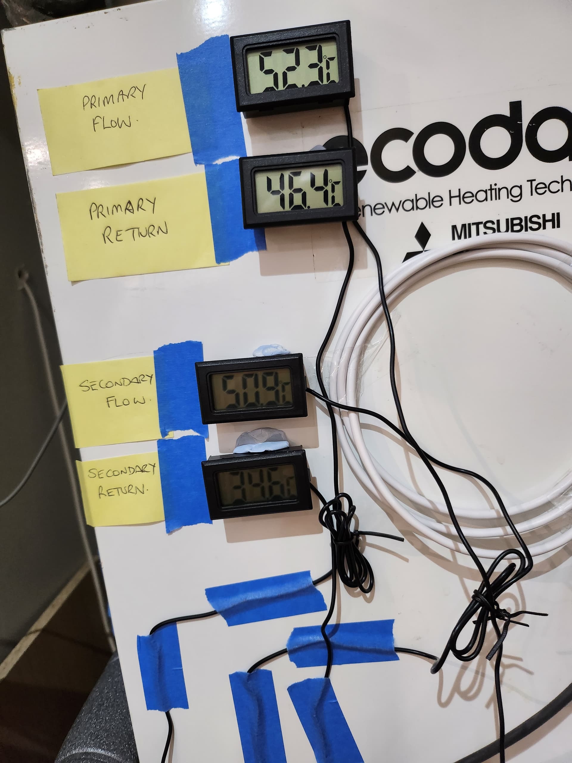
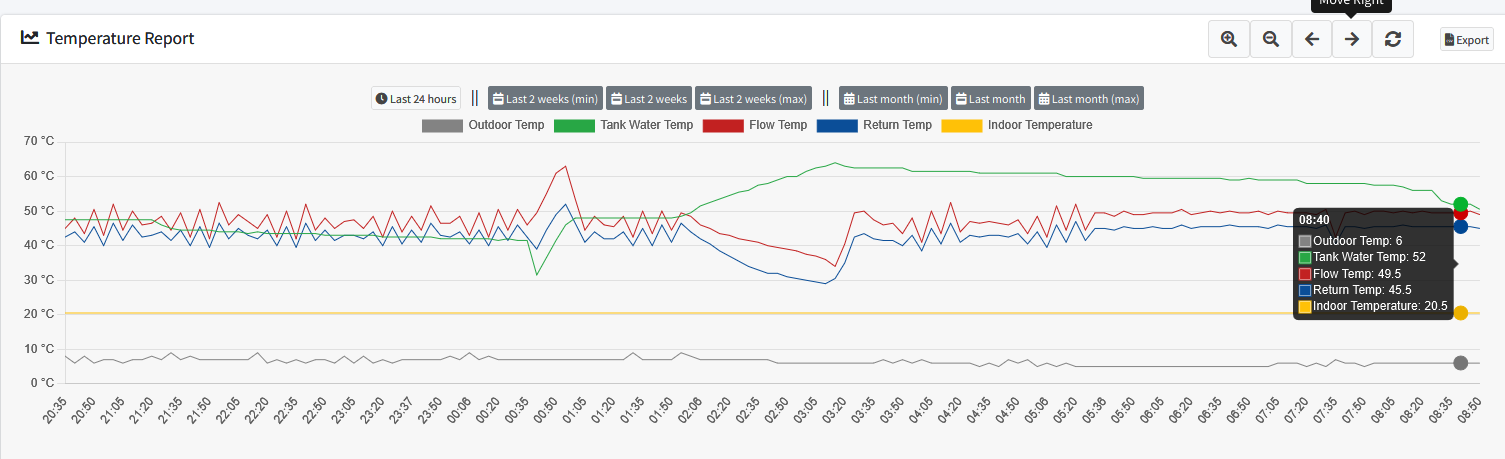
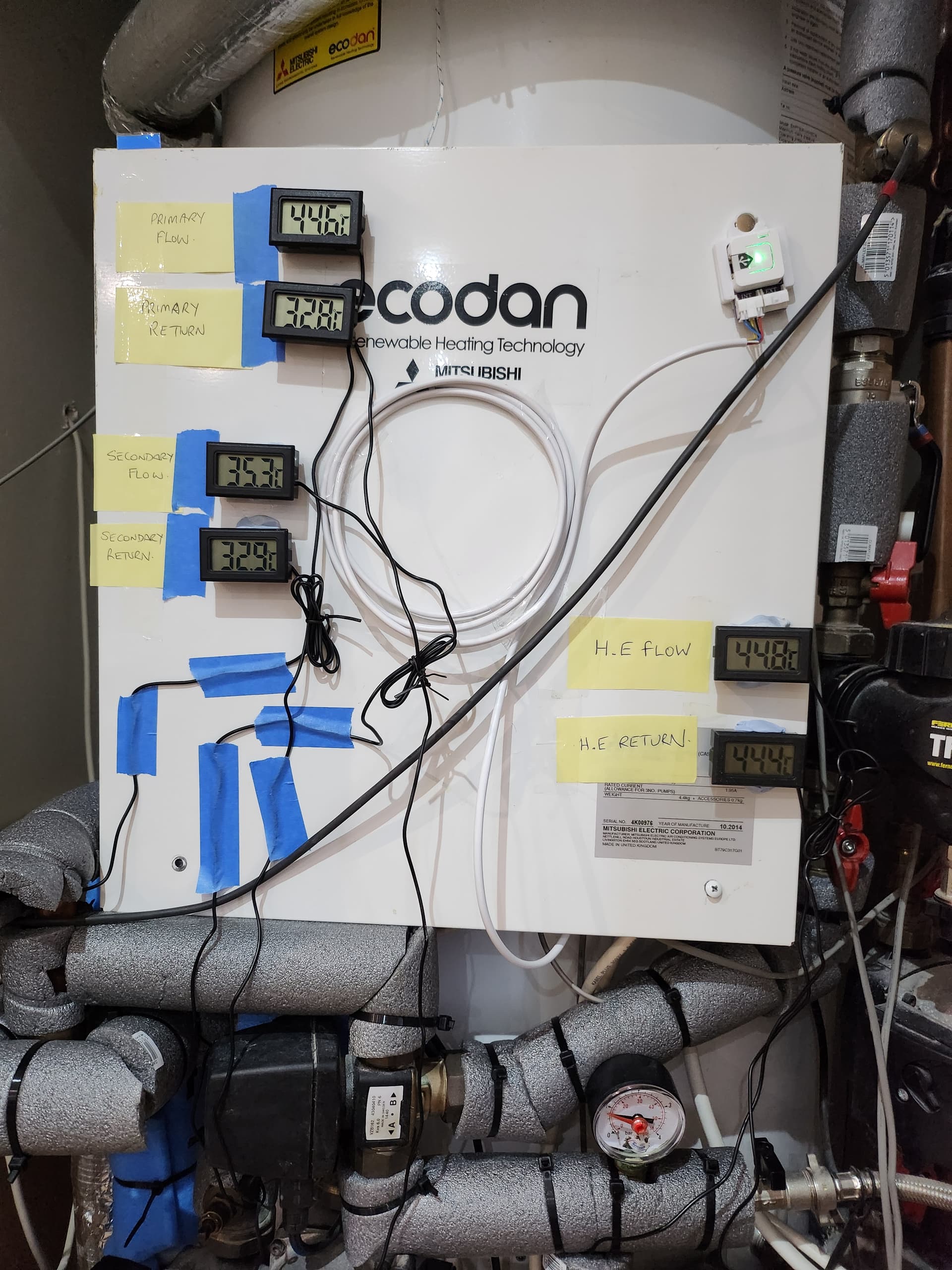
Success! The heating stabilised and I got readings at 8:42am
I also got reading at a radiator Flow-38.8C Return-31.5C
Would you agree this suggests that the problem is with the LLH and not heat losses within the floor slab?
Thanks in advance ![]()
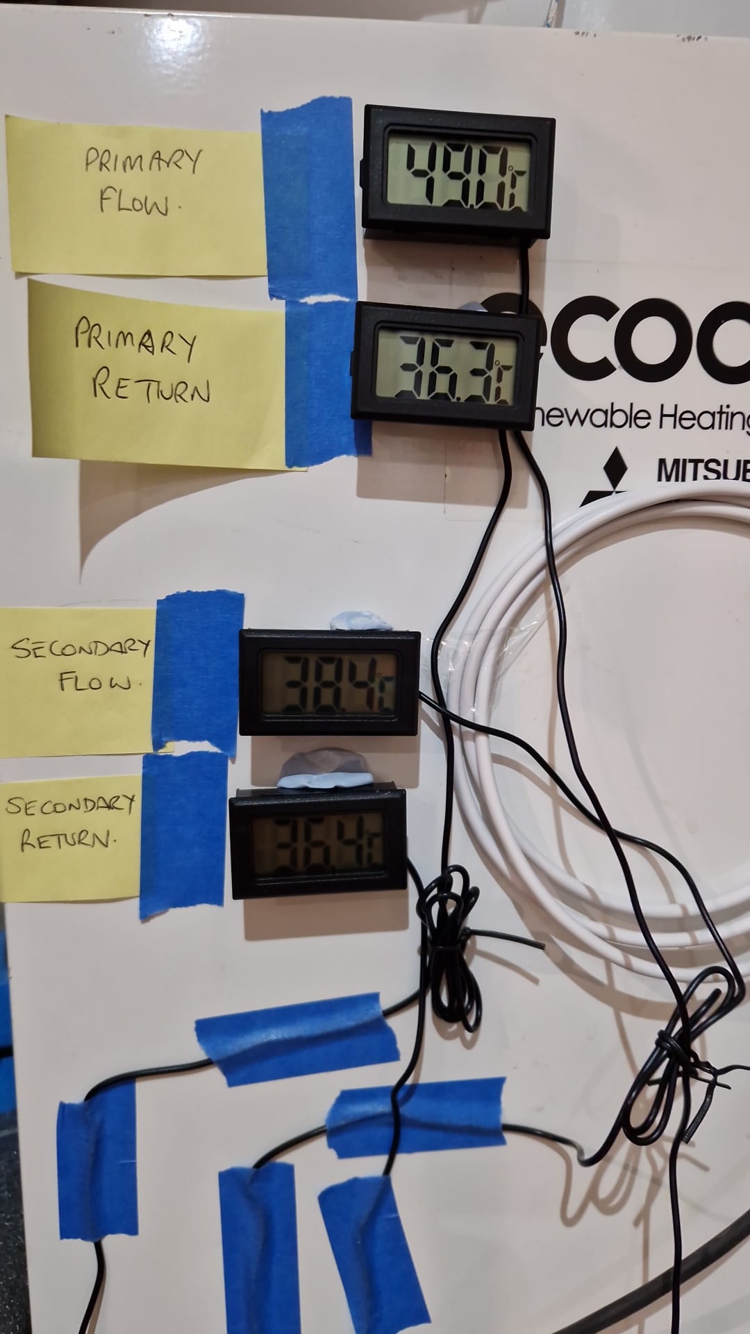
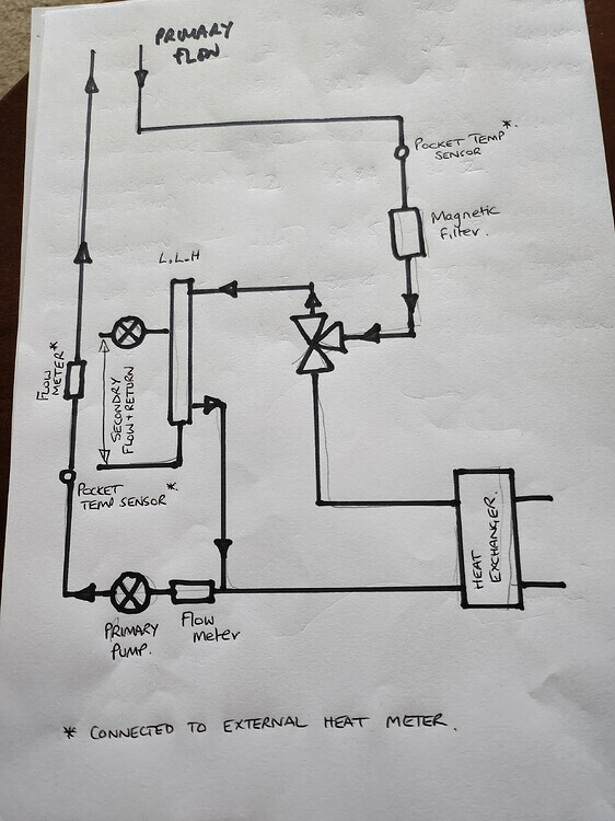
Primary flow temp (49.0) agrees with Ecodan’s own sensor (49.5), but the primary return does not (36.3 vs 45.5). This suggests an increase in temperature between the LLH and the primary pump. The secondary return (36.4) is close, giving some confidence in the sensor readings at the LLH. It’s possible that hot water is taking another route from flow to return…
I think Tim may have it and there is mixing going on.
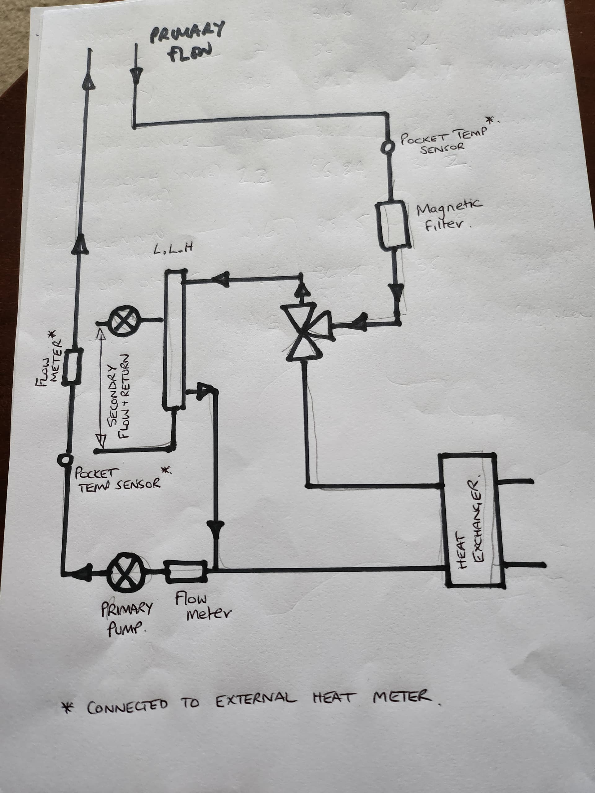
I will position some more temperature probes around the DHW circuit and see if that helps.
At least I think I can rule out heat loss in the slab as being the major factor, which good as the proposed solution was to rerun all the radiator pipes through the loft at great expense.
That looks as if there could possibly be massive bypassing through the 3 way valve, or where ever, because (9.7*44.85)+(3.3*32.85 = 13*41.8.
I’m not sure I follow your maths there John; seems you’ve used absolute temps instead of deltas.
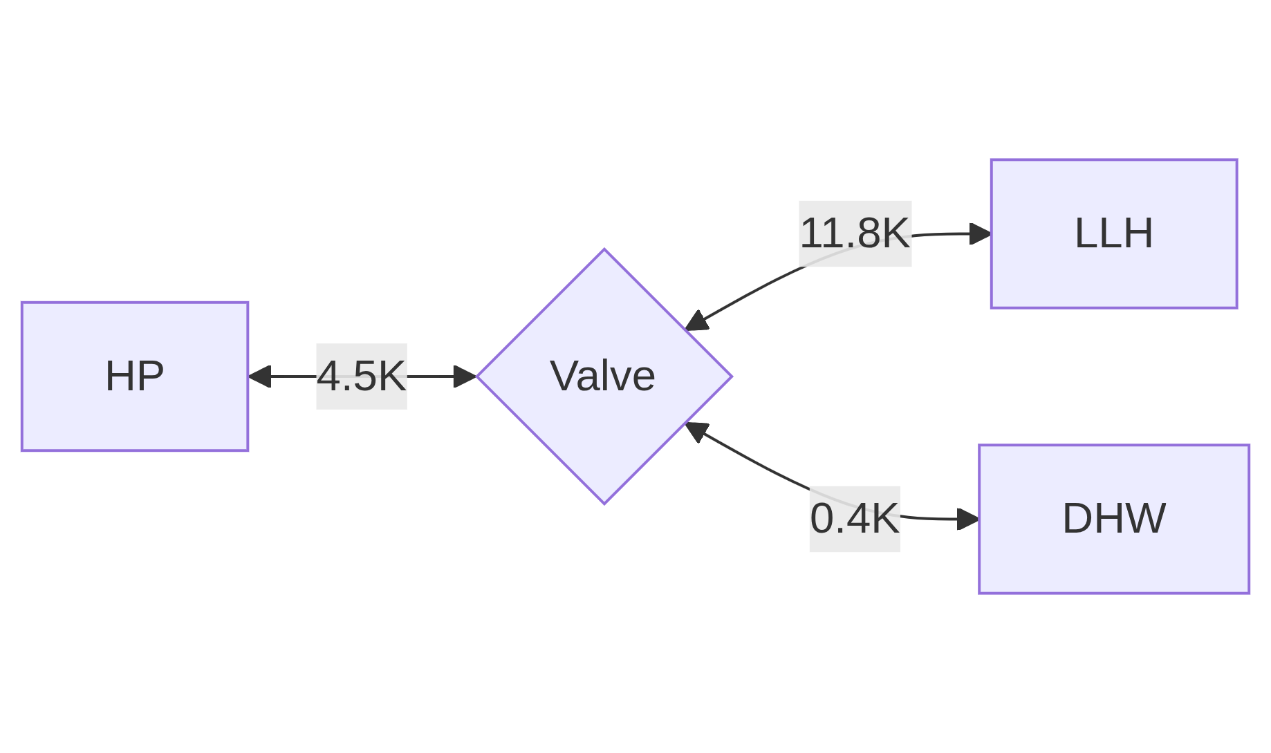
I think there are two simultaneous equations to solve here:
-
power on each side of the valve adds up to power from heat pump
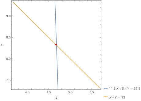
11.8° K ×Xl/min + 0.4° K ×Y= 4.5° K × 13 l/min
(ignoring specific heat capacity and conversion to l/sec as common factors) -
flow rate on each side of the valve adds up to total flow rate
Xl/min +Yl/min = 13 l/min
Solving both of these gives 4.7 l/min through LLH and 8.3 l/min through DHW circuit. Or a 36% / 64% split. If the valve is stuck in one position, this would also reduce the heat going through the HEX when heating water [I’m guessing].
Does that make sense? Is that right? I’m not 100% sure…
Ah. I was struggling there. That makes more sense to me. Fingers crossed thats the answer. Im trying to get quotes for valve replacement now. Think the model may have been superseded.
The valve is an ESBE VZB162
It is just a hunch though, I’d hate for you to replace a part and it not fix the problem. Maybe get a professional opinion from a proper engineer?
Perhaps a little ‘percusive maintenance’ might help?