IotaWatt Update - nearly complete

For those following development of this appliance, it’s nearing the design goals. Now the open eMonCMS graphing application interfaces directly to the ESP8266 on local WiFi. You can use it with or without connecting to an external service like eMonCMS. There are advantages to both. Response time generating local graphs is about 10-15 seconds.


The ESP software runs without modification except that the emoncms.org url is hard coded. So it’s a one line change. Several lines of Javascript could make that issue go away.

The board is coming in next week for the next generation hardware. The only custom piece is now a stackable seven channel ADC shield that could easily be produced as a commodity. It’s 12 bit and supports either 3.2V or 1.2V range, so it will do the 1V output SCT013s as well as the better 33mv revenue grade CTs. The voltage of individual shields (maximum of three) can be different. Each has a plug for a voltage reference input so it will do three phase without anything special.

The ADCs stack beneath AdaFruit Feather ESP8266 and a data-logger feather board with an SDcard and real-time-clock. (<$25 for the pair). Hope to have this bundled up by the end of February, but the groundhog says I’ve got six more weeks.

3 Likes

Bob,

Looking good! Thanks for keeping the community up to date.

I still wonder if there isn’t interest in a mini version with 4 inputs. I’m assuming this would be quite easy to lay out now since you have everything ready?

Simon

Hi Simon,

The new design uses a seven input ADC shield which supports a voltage reference and six CT channels. The design is scaleable so that up to three ADC shields can be stacked under the MCU-datalogger boards. So the answer is that a single ADC shield can be used to provide up to six inputs.

Eagle schematics and board files are on the IotaWatt GitHub: IotaWatt Github Site

Bob

I like the idea of the shield design. Do you think the shield could be laid out as 50mm x 50mm (2"x2")? It would be a better fit with the many prototyping services, especially since China can send the boards cheaper than the postage cost in other countries. Terminal blocks and a few more smd components would probably release the required area.

I still find it a bit hard to imagine so it will be good to see an image of both sides of the shield and the whole thing assembled.

This is fantastic, nice work!

Have you got any photos of the unit(s)?

What are your future plans for the unit once it’s been developed?

No need to shrink it any more. I just received a batch of ten boards from offshore. They look great, but will populate and test tomorrow when some needed components arrive from DigiKey. The total for 10 boards was $33 including shipping.

Here it is. The one on the right. On the left is the new board populated with screw terminals instead of stereo jacks. You can use either.

I’d like to get out of the hardware business. Not my forte. I prefer the software side. You guys have an infrastructure to distribute, so you may be interested in adding it to your store. I may approach other shield manufacturers and suggest they produce it. As a last resort I’ll see what the offshore house can offer for assembled units and maybe put them on eBay. The design is open, so I expect nothing from it.

It’s been a good learning project for me and carried me through the Northern New England winter. In a month or two, I’ll be spending less time at it.

Thanks for the photos. This is a possibility, we are evaluating options atm. With regard to automated SMT manufacture, its much easier if the SMT components are on one side and the thru-hole solders on the other since it’s not possible to use a solder wave to automate the thru-hole soldering if there are SMT components on the same side. This is not a big issue, it would not be a big issue to change this. We would also need to fit the unit into an enclosure so a physical design of the PCB would probably be needed. We would probably also put the ESP-12 directly onto the PCB.

Could you post some screenshots of the web config?

Maybe in due course when the unit is developed we could purchase a prototype unit from you to evaluate?

Not my forte. I understand the issues you describe, but lack the experience to comment on the relative merits.

From my perspective, IotaWatt is a software entity. It runs on an ESP8266, uses an SDcard, real time clock, and up to three eight channel ADCs. That’s the hardware requirement. I’ve taken care to keep the hardware specifics such as voltages, logical to ADC physical channel mappings, and reference voltages as parameter driven as possible. While not configurable through the browser based utility, the logical to physical channel mappings are just json elements in the config file. I have several different board layouts and they all run the current software with a few lines different in the config file.

After several iterations, I have come to the conclusion that there are no best answers to hardware layout. It’s all tradeoffs for the intended user. This current shield approach is designed to make it useable as a mix and match with commodity boards that exist today.

If you want to pursue this, for a variety of reasons, let’s take it offline. You should have my email address.

I stuck a copy of the browser configuration utility at iotawatt.com. If you go there, you will be running the utility. Unfortunately, it can only load the static configuration and table file in it’s directory. The status screen doesn’t work there because it can’t talk to an actual IotaWatt, but it looks like this:

Certainly a fantastic project!

Can you put up a photo of the back of that assembled prototype? (Preferably as an edit next to the other one.)

You’re totally spot on with this statement! :smile:

Thanks for the software info, it looks rather impressive. I’ll be in touch once I’ve had a chance to discuss with @TrystanLea.

Hi @overeasy

Not sure if it is permitted to ask this here, but which company in China you use to manufacture the PCB?

A link to a website would be a great help. Just want to keep it as a reference, in case I need it for future project.

Thanks in advance.

We use http://ragworm.eu

pcbway.com

Thanks! :+1:

Nice work @overeasy, I’ve added your development with credit to the Labs: Active development topics list.

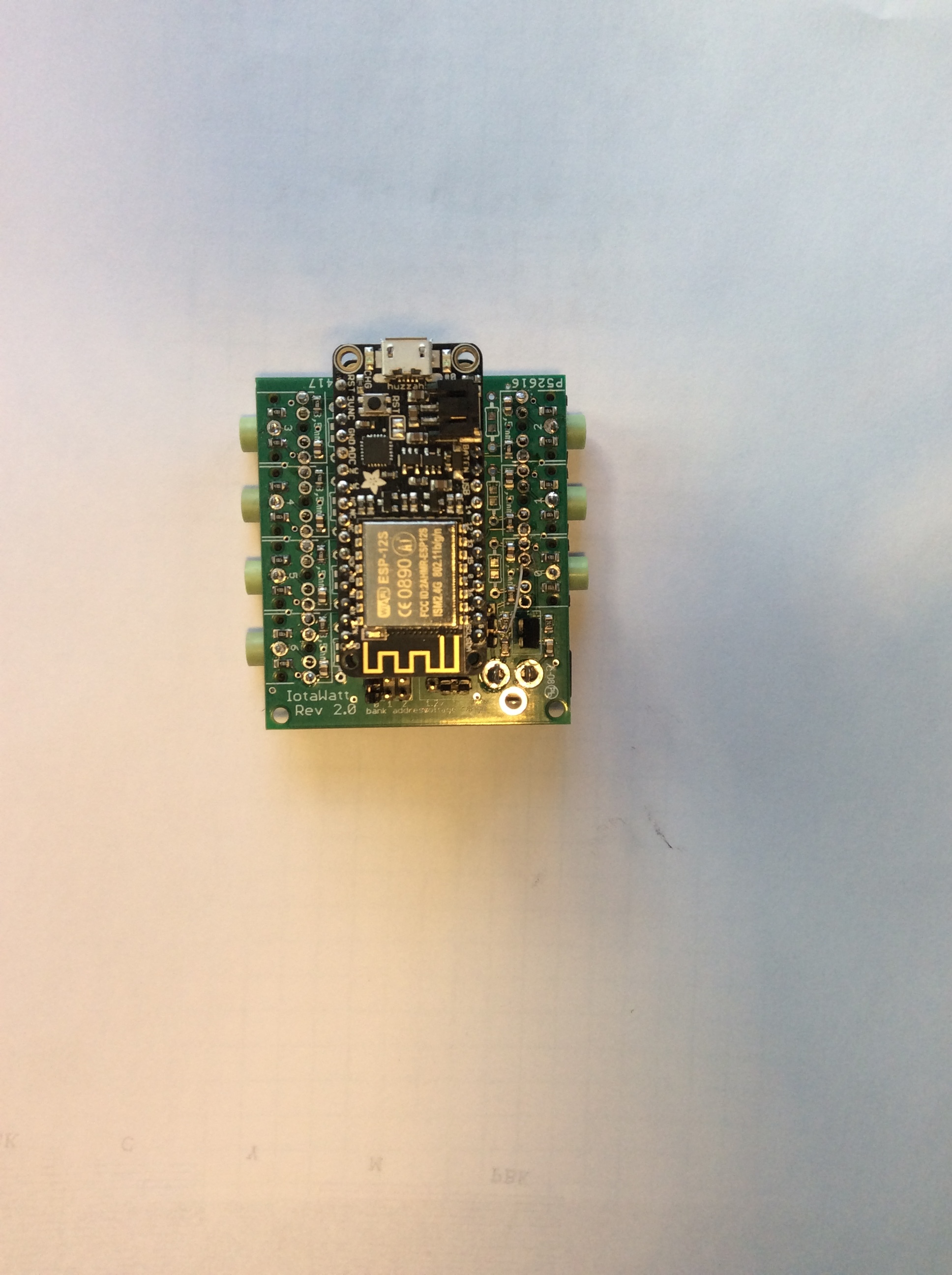
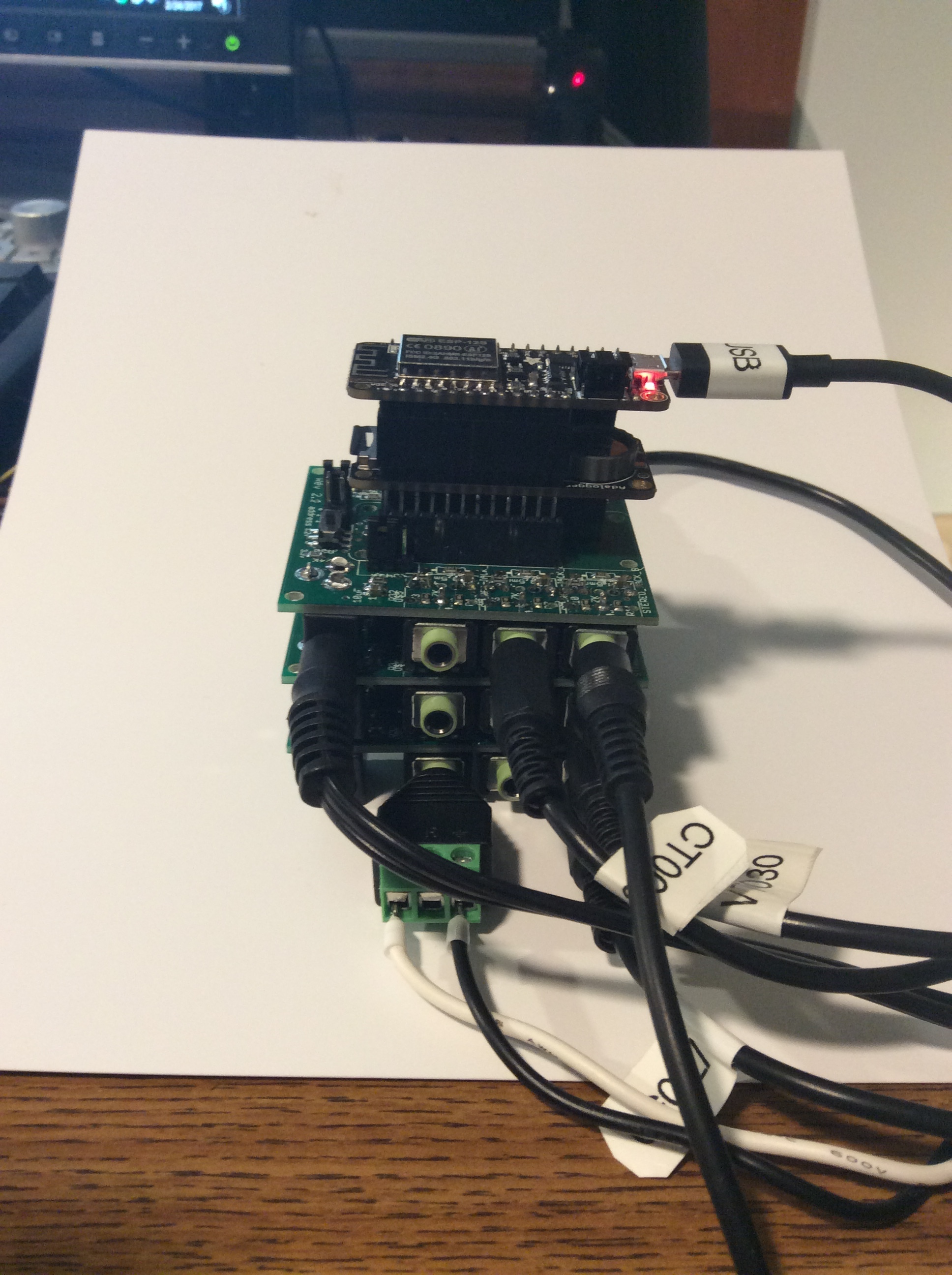
At long last, all of the major pieces are in place and seem to be working reliably. Here’s what the beast looks like. I’ll get a better picture in daylight tomorrow.


The top board is an AdaFruit “feather” ESP8266. Under that is an AdaFruit feather “data-logger” shield that has the SDcard and a real time clock. Below that are three IoTaWatt 2.1 ADC shields. The visible side has nine inputs., the other has 12 for a total of 21.

On average it samples about 35 inputs per second, so each input gets sampled about 1.5 times per second. Each cycle sampling consists of about 490 voltage and current readings. That’s at 60Hz. At 50Hz the cycle rate would decrease slightly and the samples per cycle would increase.

The top ADC is configured with burden resistors, has channel 0 set for VT input, and is running at 3.3V.

The second ADC has channel 0 set for CT input (though none connected), has no burden resistors so is running voltage type CTs (SCT013-030), and is also running at 3.3V.

The bottom ADC is configured like the second except it is running at 1.2V, so it has a 33mv CT connected and an SCT013-050 CT that is remarkably accurate at low wattage with the 1.2V and 12 bit ADC. The trade-off is that it will overdrive at about 25A.

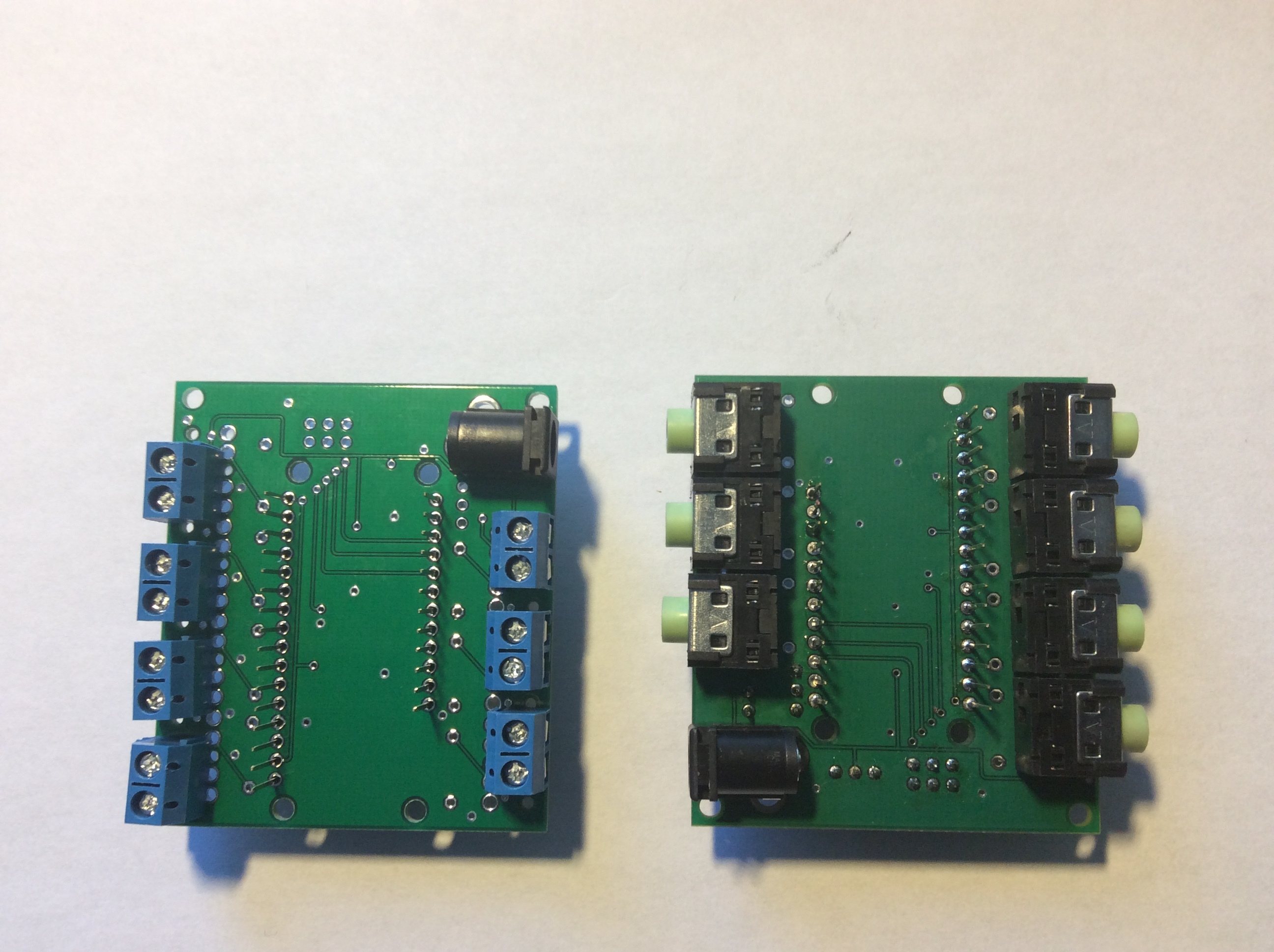
Each of the ADC boards can be configured independently, and run at either 3.3 or 1.2 volts. Any channel may be used for voltage sensing, but channel 0 on each shield has a select-able attenuation circuit and 5mm jack for a VT. With three shields and three VTs, three-phase should not be a problem.

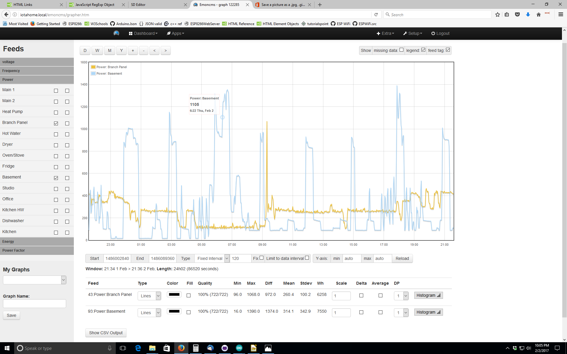
The SD log has been redesigned to support faster query. It takes about 4 seconds to serve up a 750 data point graph. I’ll get into the pros and cons of this log format later, but the typical emoncms graphs are probably the worst case. With redesign of the graphing apps, it should be able to serve up any number of simultaneous feeds in the same 4 seconds. Pie charts should be instantaneous over any time period.

Support for eMonCMS is solid. It will update in real time, and it will catch up with bulk updates after an internet outage. Because it has a real time clock and lots of SD storage, it can run without internet indefinitely, catching up when connected, or just serving the data locally on local WiFi. There’s no need for MQTT or any intermediary store and forward.

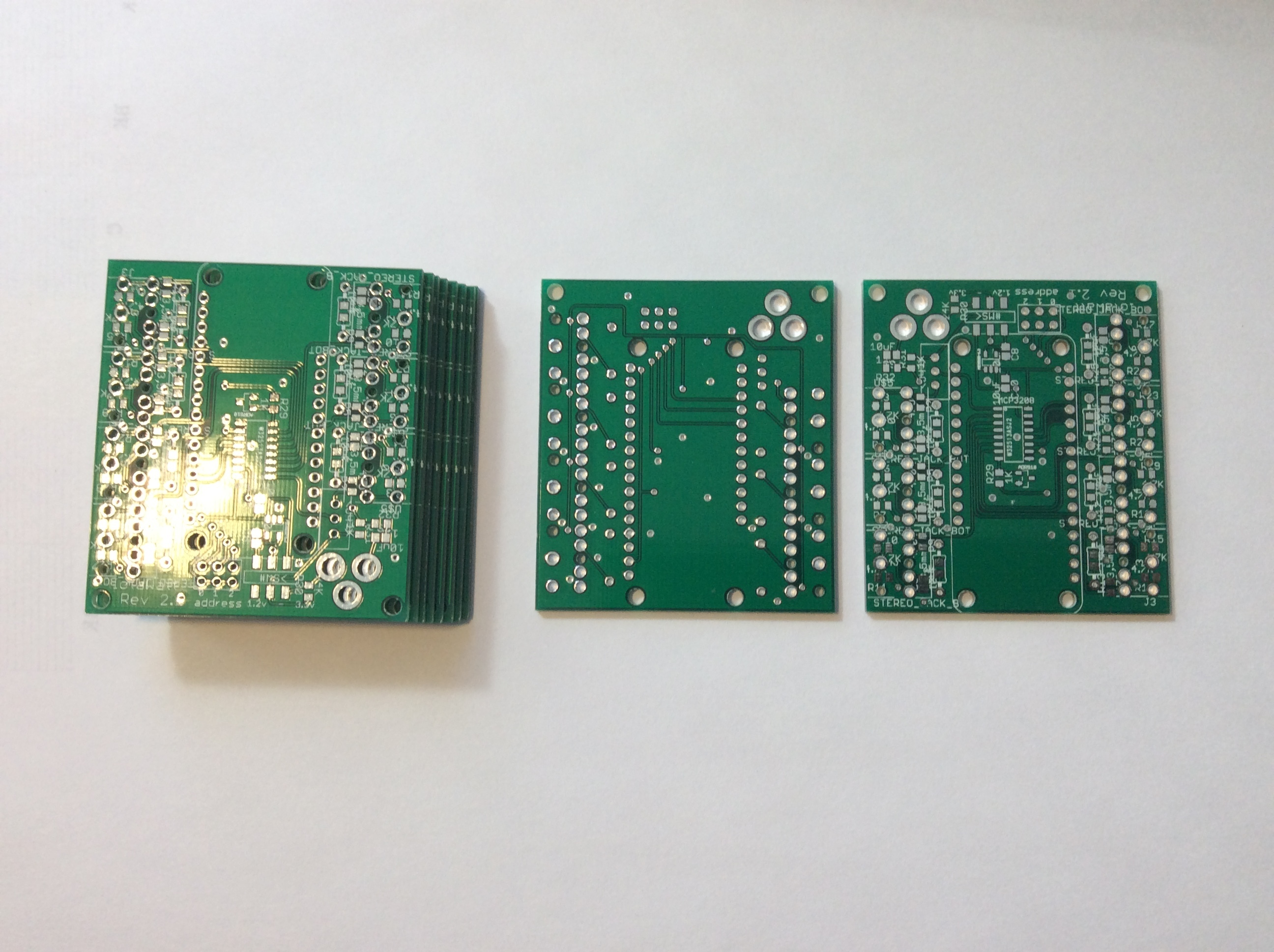
What’s left is some cleanup and burn in. I’ll be deploying a few in other residences over the next couple of weeks. Someone is currently exploring the cost of having some ADC boards built by a fabrication service. I expect the cost will be moderate in small quantities.

Software and hardware updates to Github next week.

The next phase of this project will be to integrate more of the Emon apps and probably develop some new ones.

5 Likes

This looks really great! Would like to order one or three of your feather add-on boards.
I really like it that you can store your data on SD card and upload them if a internet connection is available. I would like integrate this routine in the feather board M0 (I try to use the integrated 12bit ADC), but I’m not so skilled about programming. How is it possible to separate this routine and integrate it at other platforms?

Looking at ways to make them available. Realistically at least a few months away.[quote=“Simsala, post:18, topic:2989”]
(I try to use the integrated 12bit ADC),
[/quote]

I don’t know much about the onboard ESP8266 ADC. The software requires at least two ADC channels to read power (one voltage reference and one current reference), so the ESP alone can’t do it. If some other ADC were used, the ADC sampling is localized and could be adapted.

Good luck.

@overeasy this is looking really nice! I wanted to check that I understand correctly, do you sample each CT channel sequentially, sampling voltage and current 498 times in one 60Hz cycle 16.6 milliseconds, so 996 samples in 16.6 milliseconds or 59,760 Hz?

Why is it 35.1 AC cycles sampled/second rather than 60 AC cycles sampled/second for 60Hz AC? Is the difference due to time to switch to another CT channel?

Correct.

Basically - yes. To get the maximum samples during a cycle, the samples are just stored. No floating point arithmetic, nothing complicated, just grab samples as fast as possible. After the last zero crossing, a few extra samples are taken to accommodate phase correction. Then the samples are processed, which takes about a millisecond. So it’s too late to start another cycle and the next crossing doesn’t come around for 6 or 7 milliseconds. That’s when the device does everything else. Checks the WiFi server, writes to the SDcard, sends data to a server like eMonCms. There is a scheduler and the communication and logging is done by discrete services that are scheduled and dispatched during that period.

So each sample event takes a minimum of 1.5 cycles. The limit is therefore 40 cycle samplings per second at 60Hz. It would be 33.3 in a 50Hz world. Still, 1.5 - 2 samples each second per channel (20 max).