Hi Ian,
I have maxed out my replys, not sure this will work but I have edited my previous post.
Cheers
Ant
Hi Ian,
I have maxed out my replys, not sure this will work but I have edited my previous post.
Cheers
Ant
Somebody’s moved you up the privileges scale, so you should be OK now.
Cheers Robert,
Hi Ian,
Kensa are big on their buffers due to using single or fixed speed compressors so cycling is potentially a major issue, I don’t think they have changed to inverter but I may be wrong.
Heat pump simplicity is the key to efficiency, unfortunately as it is with a plate there is a need for your two expansion vessels although they are grossly oversized which will carry its own heat loss burden. The plate heat exchangers were always meant for two things (in my opinion) mass installer “plug and play” and reduced glycol requirements. Unfortunately as the market becomes more of a number shifting exercise, the pre-plumbed solutions will vastly increase. Daikin and others use a built in buffer vessel on their pre-plumbed cylinders which almost guarantee perfect flow rate and volume for their DT (PWM) pumps and so even a not so good install can perform reasonable well as all boxes are ticked in terms of flow rate and volume.
There is a very very good homeowner friendly system and App called Heat Engineer. That will give you a very good guide as to whether your radiators etc are all sized correctly. Most of the time on installs it is the secondary side that dictates what the primary side does and how it performs. I think it’s costs a one off fee to use, something like £10 but you can run a report on all requirements, sizes, outputs etc. for your property.
I am a very big fan of open-loop ASHPs. I can’t remember but if you can use the Samsung controller as a room thermostat and get rid of zone valves etc it would run better. I’m just thinking in regards to the Daikin Althermas, when you utilise their own thermostat the heat pump has an internal reference point and can modulate fully rather than using a simple on/off run signal. That would potentially mean only a single pump which could put you back in the “missing PWM” corner however not running multiple pumps can only be a good thing.
Ant
Hi Ant & William,
I have begun scoping the PWM Signal …
The PWM Signal is now controlling the pump , but with a very odd looking PWM Signal!
When the pump is “stopped” however I get the
The Pump changes the pump speed correctly BUT, and there is always a SAMSUNG BUT ,
When OFF the System issues an E912 error saying that the Flow sensor is still detecting too much water flow when switched OFF.
I have been trying to reduce the Flow rate to stop this , new fault, but am resigned to trying to fix ANOTHER Side effect fault !
The Reduced flow rate also vastly reduces the apparent pipe losses…
I may have to compromise and have a switched Motor with a PWM Signal controlling motor speed when required!
ian.
Hi Ian,
E912, just check that the primary pump has shut off when there is no call for heat.
You can go into self test mode and test the pump run, if you turn it on the off and the pump continues then it could be a stuck relay (closed) . Many a Samsung pump relay have had a “tap” to get them going again.
Could also be either the flow switch paddle not fully closing and the heat pump thinking (why is that open when it should be closed) usually caused by some dirt/grit in the system OR can be either loose flow switch cable(or possibly check continuity).
You might have to change the pump setting to PWM pump (4051?)
Ant
Hi Antthony and Willaim,
My SAMSUNG HEAT PUMP is fitted with an "SIKA " Audio flow sensor.
The Water flow across a central vane develops a Vortex which travels along the vane in the manner of the ripples on a flag attached to a flagpole ( SIKA’s own vivid analogy !).
The SIKA sensor is a microphone which measures the frequency of these bubbles bursting!
The frequency with which these vortex bubbles’ bust varies linearly with the rate of water flow.
These sensors are excellent examples of German engineering at it’s best …but I am afraid these sensors cannot survive the attentions of "installation Engineers ".
The E912 error can be overcome by powering the motor from a switched 240 VAC power supply, with the PWM still controlling the pump speed.
THE PWM
I have finally got a "hopefully working PWM Motor controlling the Motor Speed to control the Water Heat Power.
The Critical part in getting the PWM was setting the Water Flow rate until the PWM Signal was operating at the Center of it’s range.
If the rate of water flow is too great , or too small, the PWM Signal cannot control the water power.
I chose an operating power of half the 5 KW nominal power of the Heat Pump, 2.5 KW.
Since Power ( KW) = Water_Flow_rate ( M^3/sec) X Specific-heat_of water( KJ/(KgXC) X Delta _T
Hi Ian,
The Sika flow switches are really good however they are useless if glycol is in the system as they are unable to read a flow if the water temperature is below something like 15degreesC and so on the pre-plumbed cylinders there is normally a separate flow switch (paddle) connected to where the visual flow meter is on the flow. That way the Samsung board will know if there is flow or not (open or closed) and usually an E912 is when that flow switch is open when it should be closed hence the heat pump thinking there is flow. But if it’s not that then its all irrelevant ![]()
Thats good that you have managed to get some fashion of PWM, it will be really interesting to see if it helps to reduce cycling thus primary and secondary being a balanced supply/demand.
Dont forget your specific heat capacity will be slightly altered dependent on your glycol percentage, it could make the difference of a couple of litres per minute.
Hopefully starting to look a little positive then.
Ant
Hi Antthony and Willaim,
My SAMSUNG HEAT PUMP is fitted with an "SIKA " Audio flow sensor.
The Water flow across a central vane develops a Vortex which travels along the vane in the manner of the ripples on a flag attached to a flagpole ( SIKA’s own vivid analogy !).
The SIKA sensor is a microphone which measures the frequency of these bubbles bursting!
The frequency with which these vortex bubbles’ bust varies linearly with the rate of water flow.
These sensors are excellent examples of German engineering at it’s best …but I am afraid these sensors cannot survive the attentions of "installation Engineers ".
The E912 error can be overcome by powering the motor from a switched 240 VAC power supply, with the PWM still controlling the pump speed.
THE PWM
I have finally got a "hopefully working PWM Motor controlling the Motor Speed to control the Water Heat Power.
The Critical part in getting the PWM was setting the Water Flow rate until the PWM Signal was operating at the Center of it’s range.
If the rate of water flow is too great , or too small, the PWM Signal cannot control the water power.
I chose an operating power of half the 5 KW nominal power of the Heat Pump, 2.5 KW.
Since Power ( KW) = Water_Flow_rate ( M^3/sec) X Specific-heat_of water( KJ/(KgXC) X Delta _T
2.5 = Flow_rate X 4.3 X 3
Or
Flow_rate= 2.5 X 60 /(4.3 X 3) = 11.5 litres/per minute.
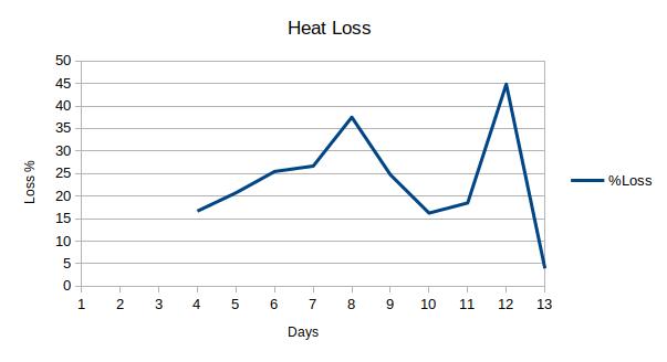
When the Water Flow rate was reduced to 12 lpm the following results were obtained.
The Losses were reduced considerably…
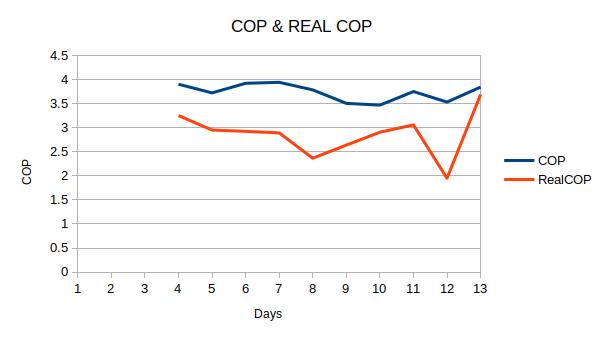
While the REAL COP was also improved
I have no doubt that most of these improvements would have resulted from the reduction in flow rate , but , I am , at least for now gratified with the improvement !
My "Heat Pump has TWO PWM Motors , however , with the Secondary post Heat Exchanger water loop still hyper-cycling…
This time, however, I have no way of supplying a signal to the second PWM Motor…by I am thinking about an Arduino…thinking!
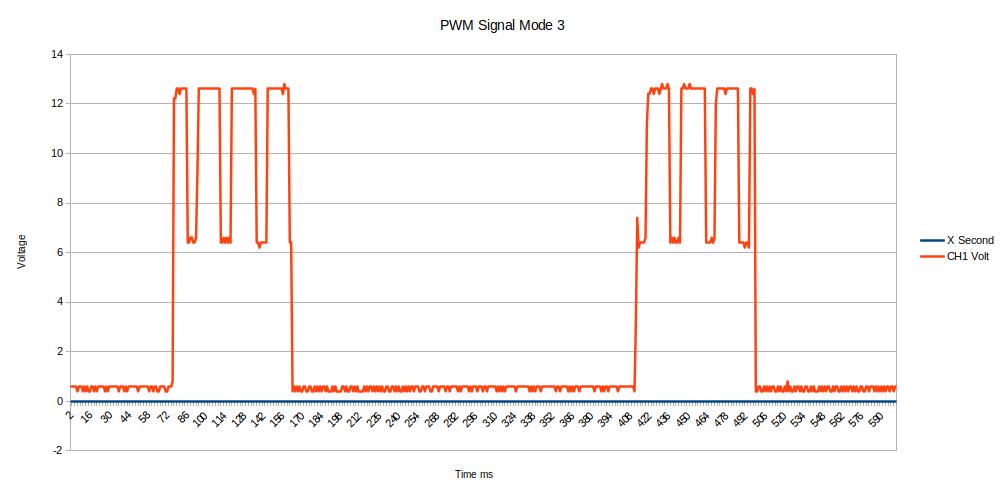
I have scoped the PWM Signals to find the operating point …
This curious PWM Signal shows an operating point the Mark to space ratio is 92 over 238 , or 38%.
ian
That is an amazing improvement! Well done.
Short story- a Samsung engineer has been to a property and told the homeowner that their 12kw unit needs a fix flow of 35litres per minute. This is correct in theory based on a 12kw heat loss. However the property has a peak heat loss of 7.6kw and so even at worst case which is -4 for the area the heatpump would short cycle, if we then consider the majority of the heating being used when it is between 3>8degC outside then this will only make the issue worse. So good to see your improvement, especially for a wider audience with similar issues.
I am not sure of how you could modulate the secondary side pump but you are correct in that PWM will likely not be possibe.
With the flow rate directly being proportional to output required, and output required being based on weather compensation “water law” flow tenperature then is there a way to have the secondary pump power based on primary pipe temperature?? If the pipe going in to the primary of the plate heat exchanger is 30degrees then you need 12l/min… if it is 35degrees then 18l/min. And so on? Not sure if thats possible but some form of thermistor based idea?
My electronics is not the best so could you put the last paragraph in to “laymans terms” just to help me understand.
Cheers
Ant
Hi Ant,
This morning my tremendous improvement has proven to be an illusion!
The Grundfoss pump shows not sign that it is responding to the PWM signal from the SAMSUNG PCB control board.
Following my trumpeting of my apparent success in correcting the losses in my heat pump I have to admit that the supposed improvement was an illusion!
Could I ask anyone out there a question?
When working how does your Grundfos motor show that it is under PWM Control?
Is the green LED flashing at 12 HZ indicating External PWM Control.
Is the Green LED flashing at 1 Hz indicating that the Pump is under Manual control?
My “Grundfoss UPM3 FLEX AS” shows no sign that it is actually working despite being fed the correct 12 V PWM Signal .
Oh how I wish I had installed the system myself …You do not know the level of incompetence shown by some installers!
ian
Hi Ian,
That’s a shame to hear, will await responses in regard to PWM.
Am I right in thinking that the 1st LED is RED and the 2nd LED is YELLOW in PWM control?
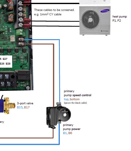
Just to confirm, as standard on a fixed speed pump it would usually wired in to B7 and B8 on the board terminals.
If using a PWM pump, it is wired in to B1 and B6 with the PWM wired in to the two PWM terminals:
Thanks
Ant
The Wiring between the Reference/Signal on the SAMSUNG PCB is different on some GRUNDFOS drawings.
I have tried both the B1/B6 and B7/B8 for Neutral and mains. B!/B6 is on all the time while B7/B8 is switched. I must use B7/B8 because I get e912 errors from the noise when switched OFF.
Still not working…
I have put an pulse generator on to motor PWM pins it works perfectly!
So I have a SAMSUNG Sig/REF working and a Motor PWM working, but , if I connect one to the other nothing, the signal is just reduced to zero!!
What is going on??
ian
to all,
GRUNDFOS motor INDICATION of PWM operation.
More revelations about the Grundfos PWM Motors!
I have connected my oscillator (to the Brown(Sig) and blue(Ref)) wires and discovered that my elderly motors do not indicate that they are working in PWM mode!
WARNING.The cable Colours given by Grundfoss on some of their manuals can be wrong.
The REF signal out of the SAMSUNG PCB should be connected using the BLUE wire.
The SIGNAL itself SHOULD use the BROWN wire!
No RED LED lights up , no 12 HZ green LED it just works!
I have used my second , Radiator circuit motor, for this test.
Grundfoss have obviously changed the PWM indicators several times since my pumps were produced.
I will now return to the mystery of the dying PWM signal fed to the First Grundfos motor!
The PWM signal was overloaded when previously connected to the primary loop motor PWM Input…
My respect for Grundfos and SAMSUNG has just disappeared …
Here is latest on the PWM saga…
My Grundfos motors work under PWM when fed from an Oscillator.
When Working under PWM from the Oscillator , my Grundfos motors show No indication that they are working in PWM.
For my system I have no way of knowing if the PWM system is working other than looking at the Changes in Flow rate.
I have no indication from my Grundfos motors themselves, that they are working under external PWM control.
The System always displays the same yellow LED’s wither the PWM is working or NOT Working.
My Primary Grundfos Motor is fed with the SIG/REF signal from the SAMSUNG PCB.
The SAMSUNG PCB is supplying a signal when the Grundfos Motor is NOT Connected…

When ,later I connect the SIG/REF to the PWM Motor I get the following…

The Grundfos motor is overloading,killing, the open circuit SAMSUNG PCB SIG/REF signal.
The user, me, cannot see the non-working PWM system because it reverts automatically to the Manual , everything to maximum mode!
Can anyone else see any difference in their SAMSUNG ?
Does your GRUNDFOS display the PWM STATUS , PWM ON or PWM OFF?
If the PWM system does not work the user would be left …none the wiser!
ian
I have now tested my Grundfoss motor on my Primary Heat Pump to Heat exchanger loop.

compared to my first, Radiator loop Motor

The Radiator motor is more linear .
From the Primary Grundfos motor I have chosen an operating point at 40 % PWM giving a flow rate of 9.4 lpm.
This method of setting the flow rate operating point is less lossy than adjusting the balance valve.
ian
Hi Ian,
Is that an indication that you have managed to solve the Samsung/Grundfos riddle?
If so, how have you managed it?
Cheers
Ant
hi ant ,
I have abandoned the SAMSUNG PCB as a source of a PWM Signal .
The Output signal , SIG has both a 6.5 volt offset and a very high output impedance.
The Signal output from my Control PCB on SIG/REF appears to be faulty or incompatible with the motor load.
The Scope is connected to SIG with REF connected to the scope earth…
The “Signal” SIG drops to 1.6 V olts DC when the Pump is connected to the PWM input to the motor, the Brown wire.
A 1k resistor across the SIG/REF also kills the signal.
The Output impedance of the SIG/REF is far to high causing the motor to kill the signal.
The Output “signal” is also offset by 6.5 Volts DC .
I do not know but I may have damaged the output chip in following the conflicting wire colour advice. Possible , but unlikely …the circuit should easily withstand the wire reversal.!
With no displays of any kind, the unsuspecting User has no way of determining if the PWM system is working or not!
When the PWM does not work the user is presented with an apparently working system defaulting to the Maximum Flow rate…
I have decided to abandon the SAMSUNG PWM Signal and implement my own PWM Signal using an Arduino to control and balance the flow through , in my case, BOTH PWM Motors.
The Balancing , or positioning the flow rate into the centre of the control signal width , as shown in the Piping Installation instructions on page 58 of the new installation instructions will be my starting point.
Something is amiss with the SAMSUNG Explanation as to why SAMSUNG alone, of the HEAT PUMP Manufacturers, does not automatically install PWM controlled pumps.
Hi ANT,
I am now convinced that my particular SIG/REF output from my Control PCB is faulty.
I have however finally found a way of testing whither the PWM System is working .
If the Grundfos motors are supplied with a constant 240 vac from Pins B1 and B6 and the PWM is NOT Working then the system will after a 10 minute interval display a E912 ERROR.
If the Grundfos motors are supplied with the switched 240 vac from Pins B7 and B8 and the PWM is either Working OR NOT Working the system will display NO warnings OR ERRORS on either the SAMSUNG OR the GRUNDFOSS Motors. The user will have NO Indication whither the PWM system is working OR NOT.
My Particular system , and I suspect some others, is defaulting to the MAXIMUM MOTOR SPEED giving NO INDICATION of the PWM Status.
I am NOW driving my system from TWO !0 Khz Waves with a 40 % DUTY Cycle setting my Flow rates to 9.4 lpm .
i know that other users will have working PWM Systems …
Please give any evidence about the PWM Working or NOT Working ?
ian
Hi All,
With my PWM driver chip not working I have been Controlling Both of my PWM pumps using a Pulse Generator.
The Pulse generator is set to 10 Khz frequency with Duty cycle of 40%.
I have stopped my Hot water system and switched on my 50 litre Volumising tank.
I have measured the resulting COP and REAL COP , REAL COP being the power measured by a water power meter.
The COP & REAL COP are …

The Loss between the Heat pump and the Power Water meter…

Both show a n improvement …but I will average the results over several days before reaching a conclusion.
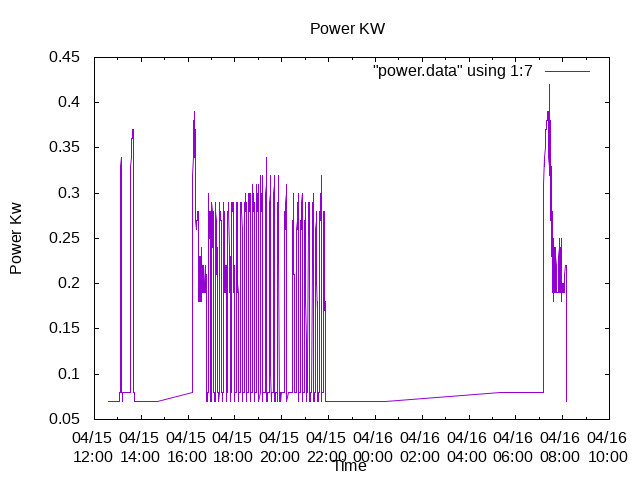
My Power measurements clearly show continued Hyper-Cycling …

So I still have hyper-cycling …
In close up the cycling is…

The Cycling time is 21 mins …an improvement , but I will await several more days of data before cheering too much.
The Noticeable Initial leading edge power pulse is a result of charging the Motor Charging capacitor.
As a visiting SAMSUNG ENGINEER said, “This charging current causes the PCB Relays on the SAMSUNG CONTROL board to Arc , and eventually prematurely fail”.
The SAMSUNG Engineer recommended fitting the in Series Power Relay shown on page 23 of the old SAMSUNG manual.
ian
A comment by a visiting Samsung Engineer, with perhaps a drop of Gallic cringe , says it all…
" Perhaps Only the Germans Really Understand how Samsung Heat Pumps Really work!"
ian