Incompetent Installers , incompetent regulation Do I need a MIM-B19N?

Hi Glyn,

My visiting SAMSUNG engineer could not explain why the PWM driver does not work on many SAMSUNG Heat PUMPS.

He, himself, could not get the PWM motor driver to work.

That is the probable reason that the Motor(S) are still destroying relays, and that the in series Relay shown i on page 23 of the Samsung manual should be implemented.

ian

Have you checked to see if the PWM connections to the pump are correctly connected on your controller

That’s interesting - my Freedom HP installation manual doesn’t suggest any connection to that.

I have 2x UPM3 AUTO 25-70 130 ZZZ; I’ve tried varying the speeds on both but performance seems best with both running at top speed.

Hi Glyn , Christian,

Given the Admission by my visiting SAMSUNG Engineer that the “PWM Subsystem may not work” I must assume that many SAMSUNG HEAT PUMPS have the PWM subsystem disconnected.

My Wiring is exactly as per your diagram.

No Signal is output on the TWO PWM Signal pins , with the Green LED issuing a 1 HZ Warning that it can see no signal.

The Grundfoss manuals states that “when working the PWM Green LED will oscillate at 12 HZ”.

A meter on the pins shows DC of Zero volts.

Sorry, but many SAMSUNG heat pumps Do NOT have PWM Motor control installed.

The Further admission by my visiting SAMSUNG Engineer that the Additional Series Relay is intended to “reduce contact sparking” further adds to the disquiet.

Now suffering from “Short Cycling on both my primary AND secondary Water loops” a working PWM control would both reduce energy consumption and reduce the Violent switching , short cycling , on my primary water circuit.

ian

Hi All,

As an example of the power consumed when operating without a Ballast tank on my primary water loop please examine the following on 29 th March…

3297

When the ballast tank was used …the result is the following…

3289

Conclusion
A 50 lire ballast tank greatly reduces , but does not entirely eliminate short Cycling.

Short cycling is also apparent on the secondary water loop…

349

ian

Following the visit of a SAMSUNG Heat Pump Engineer the following points have emerged.

  1. The GRUNDFOSS MOTOR Pulse Width Modulation Does NOT work on many SAMSUNG HEAT PUMPS.

  2. When the Pulse Width Modulation is ZERO the Motors will be driven at MAXIMUM speed . This is a safety feature to transport excessive heat following a electronic malfunction.

3.When No PWM signal is available , the motors will be driven at maximum speed consuming a larger amount of energy.

  1. The Larger starting currents are carried by, and damage the PCB mounted relays.

  2. The PCB relays can be protected by the addition of another Relay in Series with the PCB relay.

  1. When operated with WEATHER COMPENSATION, aka SAMSUNG WATER LAW , the RUN demand from the control box to the Outdoor Heat Pump is the logical AND of the Water LAW Thermostats AND the ROOM Thermostat.

7.With a Heat Exchanger fitted to provide isolation of the HEAT PUMP from the RADIATOR water circuit the system may Short cycle at TWO oscillation frequencies, one for each water circuit .

  1. Multiple Short Cycling could be limited with the use of a “LOW LOSS HEADER”.

My Installation is still not working despite 10, TEN months of complaints!

Fitting these upgrades is anything but trivial!!

ian

Hi ALL<

Can anyone supply the name of a supplier of a SAMSUNG HEAT PUMP PCB with a working Pulse Width Modulation , PWM, driver for a Grundfoss PWM Motor?

A visiting SAMSUNG Engineer was unable to explain why so many PCB’s DO NOT supply PWM signals to the supplied PWM Motors!

Virtually ALL GAS Boilers have PWM Motors fitted and working , including the gas boiler removed from my house before the "installation " of this SAMSUNG HEAT PUMP have PWM Motors with working drivers!

I have been told yet again:

"THe MCS , NIC and the RECC cannot help when your “installer” has been stuck OFF.,

You must seek legal advice "

As a 75 year old OAP I cannot possibly "take legal advice !.

ian

COP and REAL COP

The following graph shows the difference between the Samsung claimed COP obtained from the Energy usage on the front panel and the ACTUAL COP i Obtain on the RADIATOR CIRCUIT.

My Tank and piping losses are averaging 25% and that with the HOT WATER SWITCHED OFF.

I will experiment by restarting the HOT WATER system but expect the actual performance to further deteriorate.

The System continues to oscillate consuming yet more electricity …

power

The "Regulatory Charities , the MCS,NIC,RECC continue to deny any responsibility, advising “Legal Action”.

So much for "light touch regulation by Registered Charities "!!

ian

PWM on SAMSUNG Heat pumps is not matched to my supplied Grundfoss PWM Motors.

With a blushing SAMSUNG ENGINEER weakly trying to avoid eye contact when explaining why the PWM motor driver does not work on many SAMSUNG Heat Pumps, I have abandoned confidence in SAMSUNG.

On many SAMSUNG Heat Pumps the Range of the PWM Signal output from the SAMSUNG PCB does not match the Water Flow required by the heat pump.

.My own PWM PCB output , monitored with a Scope , shows no sign of activity , probably having been removed because of the mismatch between the PWM signal and the required Water Flow .

My Heat pump will continue to short cycle on the Radiator Side of my Heat exchanger.

The PCB motor Relay will continue to arc.

The System will continue to consume excessive amounts of electrical energy in running two Grundfoss motors .

ian

A NEW VERSION of the SAMSUNG INSTALLATION manual is available!!

https://midsummerwholesale.co.uk/pdfs/ehs-install-guide-samsung.pdf

Get your copy out NOW …It is a vast improvement on the old version!!

A world record for a Hyper-cycling SAMSUNG HEAT PUMP.

Have a look at my Hyper-Cycling ( my new word invention ) SAMSUNG HEAT PUMP!

2178

I make it 94 Oscillations in one day.

My Cycling Juice consumption is also a record …circa 9 KWh!

2178

My HEAT PUMP PWM continues to fail , resulting in the % loss rising to circa 25% !

losses-14-04-23

These graphs were obtained when the HOT WATER subsystem was switched OFF, being far too expensive in Juice and Money!

iantelescope

Hi Ian,

New to this forum.

I am currently at work so only skimmed the prior discussions but to catch up:

You have a Samsung heat pump which has a plate heat exchanger on the cylinder so assuming Freedom heat pumps.

Is the system glycol filled or using anti-freeze valves?

Heating cycling - assuming weather compensation (water law) is set and room temperature is stable? (Make sure your controls do not have TPI) if you have third party thermostats.

Is it a radiator system or are do you have UFH/Radiators/Fan convectors?

When your installation was done, you should have received a full heat loss calculation, this will include design outdoor ambient temperature and room x room outputs.

Sorry if this has all been discussed prior :slight_smile:

Ant

Welcome, Ant, to the OEM forum.

I think you will need to take time (quite a lot of time) to catch up on what’s been written so far, and I’m sure all ideas will be welcome. Collectively, I think we’ve managed some improvement, but more would be gratefully accepted by Ian.

Hi Anthony,

My SAMSUNG-TELFORD HEAT PUMP with tank was put together by TELFORD using a , then standard, SAMSUNG 5Kw Heat pump .

The System was originally designed as one of a pair of Heat Pumps for a location in the “South of England”.

The original order fell through and the Double order divided into two separate Heat Pumps.

One of the Heat pumps, sold to "City Plumbing in Warrington was transferred to Glasgow , Hillington where it was sold to my chosen “installer”.

The delivered Heat is not what I ordered and all of the original documentation “has been lost”.

My “installer” has been Struck OFF Twice for his performance with both my own Heat Pump and another .customer.

None of the original " installer designs and computations " correspond to the subsequent installed system.

This horror story has been running for some 10 months with the "Regulatory Charities, MCS,NIC,RECC " now intent on giving my "installer his NIC "licence back!

So if you live in Scotland check the recent history of your “installer” against the NIC inventory for the year 2022-23.!

Technically the Heat Pump to Heat Exchanger is loaded with Glycol , the secondary Radiator loop being loaded with an anti-corrosion substance.

The secondary Radiator circuit was “designed” by my “installer” , however, he maintains that he has “lost the documentation”. Heat loss calculation are meaningless in these circumstances.

The Heading of this forum spot On:
Incompetent Installer , Incompetent Regulation from the Registered “Charities” MCS,NIC and RECC.

ian

Hi, thanks Robert.

Hi Ian, not sure how one “loses” their calculations, they would have been perfect for checking your flow rates, temperatures, radiator sizes etc. as I’m sure you are aware.

SO,
Based on it being a 5kw ASHP, predicted flow rate in the primary circuit around 15-16l/min maximum?

Whenever I have conversations regarding heat pumps, the three big points are:

Volume for Defrost (I see you now have a volumiser).

Flow rate (this is the problem with the pressure drop on plate heat exchangers with this type of cylinder). I recently had a conversation with an installer who had a 16kw Samsung with the Telford Pre-Plumbed cylinder and with the primary pump at maximum it was only producing around 18l/minute (roughly 6kw) and so the heat pump never got the house warm, and consumed a lot of electricity in trying. They then swapped the plate HEX for a low loss header, ditched filling the entire system up with glycol and used AF valves. now they are seeing 38l/min (around 13kw) and so the heat pump can match the house load.

Outdoor heat pump clearances (So many heat pumps are only 100mm from the wall).
I won’t mention any names but needless to say this Mitsi had a hard life.
Mitsi1

The secondary side flow rate would ideally have a close DT, something like 5-7degrees difference and will be similar to the primary. Retrofit installations that fail often tend to have the secondary side still set with a 20deg differential, reducing the MW-AT. The heat pump then has to run alot hotter to compensate.

Also, assuming with you using the two “water law” curves then your property has split heating zones, it is worth just double checking that the room thermostats are ones that do not have TPI enabled. If they are Salus, Honeywell etc. then this will send On/Off signals to the heat pump causing unneccesary cycling.
I’m, pretty sure (not certain) that the Salus RT520 has a 6 start per hour logic for radiator systems so if both zones had this then that’s a lot of starts per hour.

Another person, may not be helpful, had their weather compensation set too high, they increased their room thermostats to say 25degC (random figure above room temprature requirement) and reduced the weather compensation flow temperature until the room sat at a steady 20degC. Then bring the room thermostat down to 21degC and so it would only act as a “over heat thermostat”. The heat pump would just run at it’s lowest temperature in order to keep the room at the desired outcome.
The only other way I can think of extending run time vs cycling is to slighlty widen the hysteresis on the room thermostat from 0.5degC to 1degC for instance. The room temperature would be slightly less controllable but the heat pump would have more work to do each time it is called for.

Ant

Hi Ant,

Many thanks you have restored my confidence , in thart I have thought about most of the fixes that you advise.

Hyper-Cycling and Flow rate
My Heat Pump was supplied with TWO Grundfoss, Pulse Width Modulation, PWM Pump-Motors.
The PWM does not work possibly because the PWM output signal from the SAMSUNG PCB does not correspond to the input requirements of the motor.
An PWM output signal with the correct mark to space ratio would vary the flow rate continuously eliminating the Hyper-Cycling .
Theory…

To get the SAMSUNG PCB to control the Water flow without constantly switching , or cycling On and OFF
has proved very difficult!

My PWM Motor control does not, so far, issue any PWM signal for my PWM Motors!

This would eliminate the Hyper-Cycling caused by the primary water loop, but not those caused by the secondary, radiator , water loop!

LOW-LOSS HEADER.
A low loss header would ADD a volume of water to both the primary and secondary, Radiator water circuits. Such an added volume would increase the Hyper-cycling width in proportion to the volume added.
A great idea but my experience with my “installer” in his previous attempts at installing a volumising tank fills me with dread!

Proportional Integral
I would love to interface a continuously variable Temperature Sensor instead of the Binary Thermostat interface supplied with the standard SAMSUNG HEAT PUMPS!
The room thermostatic input on my SAMSUNG are simple switches, with a continuously variable sensor input seemingly only available in the USA , and that at great expense!
The Temperature sensors use the F1,F2 RS485 control bus to gain entry to the Heat pump controller, not consumer friendly!

Variable Hysteresis
Variable Hysteresis Thermostats seem to be unavailable in Europe, with again the USA being the only source …at great expense.

This represents only a fraction of my attempts at getting a functioning, stable and efficient SAMSUNG HEAT PUMP.

ian

Hi Ian,

Personally I am not sure why PWM is not standard on these systems as they are with many other manufacturers. As you say it would iradicate many issues, especially when the heat load is only proportional to the worst case design scenario.
Without PWM it is a fixed speed output (useless).

If I remember rightly, it is only Midsummer that seem to offer a working PWM Grundfos pump variant which is the Grundfos UPMM 25-95 but i’m not sure they’re allowed to sell them on their own as they are an OEM product. I think the UPM4 25-75’s can be used on the smaller capacity units.

I have had a look at your cylinder photo and I am intrigued as to how your volumiser is installed. Looks to be tee’d in to the flow before the plate heat exchanger but I can’t see where this then reconnects back to the system (around the back of the cylinder)?

The low loss header would hydraulically separate the system pumps whilst reducing pressure drop which would mean the circulating pumps could be “knocked down” from max to medium providing they it offered the desired flow rate. (and could possibly reduce any temperature distortion).

In reference to yours, I have never known a Samsung to work with two temperature zones, (terminals B22 + B24 from memory), it always use to throw up all kinds of problems and “suppliers” always used to avoid dual weather compensation on the Samsung Gen6 units and would only commit to a single zone/temperature system. Not sure if that has now changed.

I’m not overly ofay with Samsung but, am I right in thinking that if it is purely cycle related, can’t you adjust the miniimum run times/anti cycle times on the Gen6? It might be worth consulting Samsung prior to changing any minor breadcrumb settings but I’m sure you could set from 5minutes to 10 minutes to 20 minutes. etc.

Ant

Hi Ant,
The source of my problems is my “installer”, my builder , TELFORD, and my manufacturer, SAMSUNG.

I also think that a low loss header would be a solution to my problems…but,
given my experience every fix seems to have a cost , both literally and technically!

I ordered a “simple” SAMSUNG without Volumising tanks , Heat Exchangers or another Expansion vessel…

I now have a SAMSUNG with all of this stuff added …my motto would be “Start Simple and add bits slowly when necessary !”.

The Volumising tank was installed to fix two different problems with solutions from Two different companies.

Problem one, Hyper-Cycling on the primary water loop.
The solution to the short-cycling was the introduction of a 50 L volumising tank fitted in parallel across the primary of the Heat Exchanger.

Problem two, De-icing uncompleted.
The solution was here to fit the 50 l tank into the return pipe to the Heat pump.

Both solutions were generated by different parts of SAMSUNG servicing.

My “installer” then got in on the act and then described the SAMSUNG advice as “ludicrous” saying that he would do it himself!.

The “engineer” at my “installer” who described SAMSUNG as “ludicrous” was then secretly fired, with the 50 l tank left for two months under his desk!

Two of my “installers” "engineers appeared some two months later , saying that they did not what they were doing nor where to install the tank.

The Tank was installed across the primary of the Heat Exchanger to solve the “short-cycling problem”.

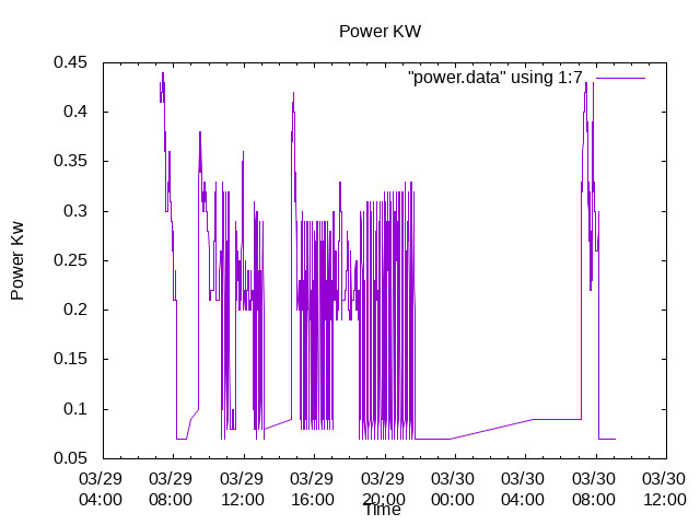
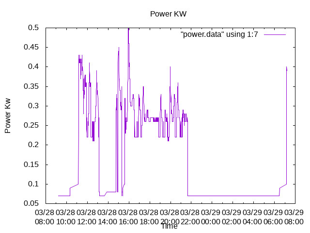
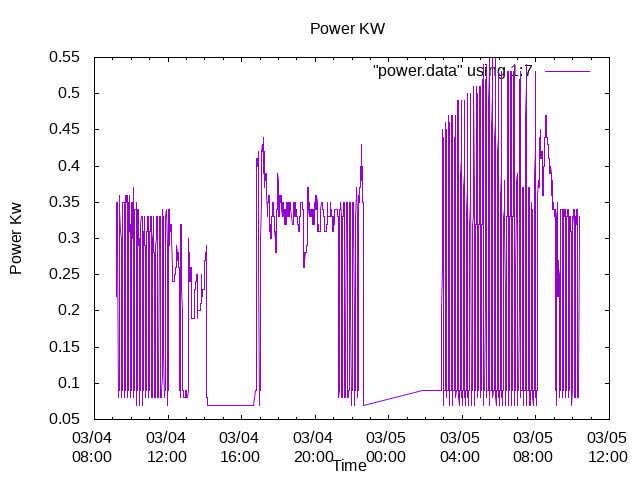
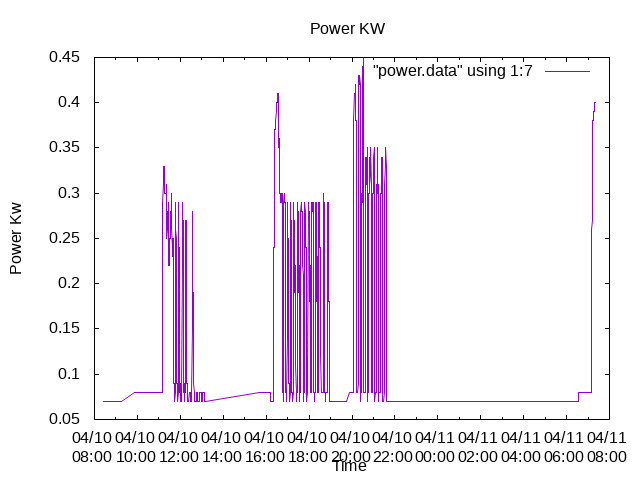
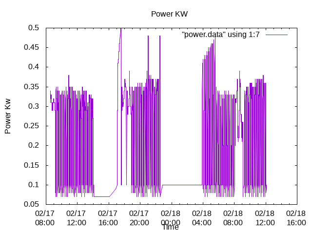
The De-icing has worked throughout winter and the shorty -Cycling has been replaced with Hyper-cycling
and an increased Energy use-age.

Yes, a Low loss header would be a solution , but, not “installed” by my “installer”.

Changing the field parameters has been my “hobby” for the last three months.

ian

Samsung aren’t wrong in that fitting the volumiser would improve defrost situations as there is quite a lot of thermal energy required for defrost. I have experience with quite a few people that have a primary volume of 10 litres (or less) and suffering from a heat pump freezing up with no thermal energy available to defrost the outdoor unit. Certain Samsung suppliers started offering a relay that allowed the secondary pump to become live whenever the primary became live meaning that although the primary was separated via a plate heat exchanger the primary could have “access” to the secondary thermal energy. This would in turn cool the room slightly but would stop the heat pump becoming stuck in defrost. It worked to a degree but every samsung engineer visit would shun the idea and recommend minimum volumes.

Fitting the volumiser in parallel in my view will just allow a short circuit for the water and so will have to be balanced/reduced flow to get any sort of benefit. We always look at volumisers to go on the return but on the heating side of the primary. Not sure if that would be possible on the pre-plumbed as everything is piped together, anywhere else on the return and heating the cylinder coil becomes a lot of extra work (i.e. heating 50ltrs of water before the cylinder starts to warm up this prolonging hot water cycle). This will become expensive as if you have the DHW heat up mode set to standard it will start to use the immersion heater after an hour.

Is the secondary side pump operating as it should? If the flow is not adequate on the secondary side then the return temperatures back will be too cold. Recently I was with an installer of a different make who had a terrible COP and the primary flow temperature was 55degC and the secondary flow temperature was… 45degC! That’s 10degC extra because the secondary circulation was so slow and return temperature coming back too cold. If the separation (small buffer) wasn’t in the design then the heat pump could have operated 10degC lower in temperature for a similar result.

It would absolutely be worth performing your own heat loss calculations, if the heat pump is too small or radiators are designed to operate at 55degC flow temperature then no matter what settings you try you will never have a system operating to its optimum conditions. You can download the MCS calculator I believe as an Excel spreadsheet.

Ant

Hi Ant,

Great to talk to someone with experience, inexperience and vanity seems to be endemic with heat pumps!

The fitting of my Volumising tank across the primary of the Heat Exchanger almost certainly resulted from an engineer at Samsung failing to appreciate that my Heat pump was fitted with a Heat exchanger.

Fitting a Heat pump in parallel has become standard practice as a replacement for Low-loss-Headers, as in "Buff up your knowledge of Buffer tanks " from Kensa.

The DE-icing problem has never appeared as the parallel tank seems to store and dump 3.5 KWh of energy from my Hot Water tank!

The parallel tank has , however, further worsened the energy efficiency. Everything has a cost!.

My “installer” performed several calculations …but then supplied a totally different Heat pump before firing the “engineer” who “designed” the “system”.

At this point I want to grossly simplify the system into a One Water loop system.

Drop the heat exchanger, Drop the Volumising tank, drop the extra Expansion vessel !

A simpler solution …a program to design water systems

In Water, pressure is analogous to Voltage in Electrical circuits.

In Water, flow rate is analogous to electrical current in electrical circuits.

In water Temperature is analogous to Voltage in Electrical circuits.

In Water Thermal Energy flow, Joules/sec, is analogous to current in Electrical circuits.

Why can’t we generate a Computer program to solve all these , currently intuitive, solutions with exact mathematical solutions ?

Do these programs exist?
ian

1 Like