As it’s d.c., and only milliamps at best, you probably have little choice other than to do an almost exact copy of the voltage side across your sense resistor - but with the op.amp gain changed, of course. (I’m assuming R2 isn’t always going to be a nice resistor.)
One point I forgot to cover - earlier you asked about unmatched resistors around the op.amp. You can make one (only one) a slightly lower value and put a low value selected resistor(s) in series to get the best balance, or go higher and put a high value in parallel. I’d tend to choose my R5 for that.
Hey Classy,
Just trying to get my head around how you managed to correct for the phase difference. That PHASECAL value wouldn’t have compensated for the ~35˚ difference of the zmpt module. Was there anything else going on in your circuit or code?
You can still use the same general differential amplifier for everything - for current (a.c. or d.c.) you’ll generally be looking at a differential voltage from a shunt, which is likely to be below 1 V, so you’ll need very careful trimming to remove the common-mode signal and of course some gain, rather than attenuation. That could be quite challenging, and you might want or need to look at dedicated I.Cs for that.
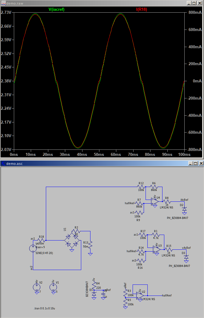
I can get a reasonable outcome but not perfect and the gain is limited to circa 0.7v per 800mA. I’m not expecting any more than this and would like to bump it up, what would you suggest? I can think of a second op-amp or using a higher value shunt (better resolution)?
For trimming would you suggest a POT for R1 (gain) and R14 (something like a fixed 3.9k res + 1k pot) for balancing? I can see how this could become tricky but the solutions I’ve seen like the INA chips are for DC not AC.
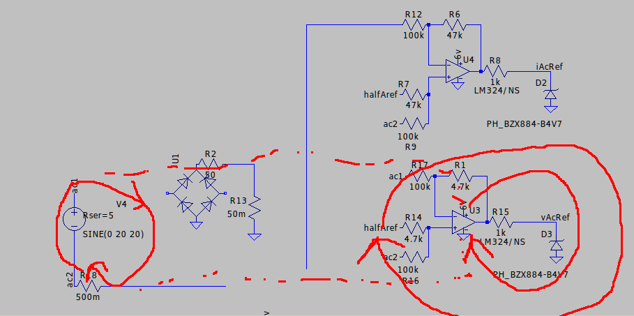
Your generator is about 30 V rms, so I’d suggest aiming for up to half a volt across the shunt (about 10 × what you have now). All engineering is a matter of balancing all the factors so that you get the best overall result. If you monitor the voltage after the shunt, it doesn’t matter how much voltage you lose to it, nor does the input load of the amplifier matter (within reason), so you can afford to reduce the resistors R9 & R12 by quite a lot if necessary. And the load of the voltage monitor is 100 kΩ, so insignificant as far as the current is concerned.
No. It’s correct in principle, in practice the adjustment that will give will be far too coarse to be practical. If you have 1% resistors all round, then work out the worst case values and how much you need to change the one you’ve chosen to have the series potentiometer to get back to a balance. The value of the resistor should be reduced by that to ensure that adding the potentiometer will give a balance, and its value should be such that you only just get a balance with all of the potentiometer included when all the tolerances go in the opposite direction.
no there was nothing else going on in my circuit or code. i connected the ZMPT directly with arduino nano and connected the SCT as shown in the LEARN section of this website.
i just adjusted the Calibration values until i got the best response. my calibration values were
I have no idea where @danbates got 35° of phase error from. The phase error for the ZMPT101B transformer alone (without the buffer amplifier of the ZMPT101B module) is claimed to be ≤ 20’ (minutes of arc), so your phase calibration value is entirely believable.
However, the circuit diagram that I have seen for the module incorporates two op.amps with a band-pass response tuned to about 29 Hz, so there is a huge phase error of around 40° at 50 Hz (55° at 60 Hz) so he might well have measured that.
That sort of error means that this module is unusable for real power measurements.
And that, unless you have the know-how and the test instruments, is the only way you could do it.
@danbates did a detailed analysis on ZMPT earlier. he posted it in this thread. you can find it at the top of this thread.
can you please explain it a bit? i believe i’m getting correct readings even with varying resistive and inductive loads. what problems might occur during real power measurements?
Not following what you mean with the resistances. My impression was the resistors had to be as equal as possible, i.e the 2x100k’s and 2x680k’s. If I use 1%'s and use the floor/ceiling values I see quite a change in the accuracy. It would be easier to trim them out with a low value POT (the 1k was a bad example, the value would be to cover the % error of the resistor in question). The way I see it I need two POT’s to balance one side equal to the other.
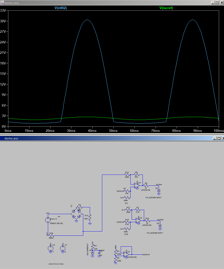
Although my generator is 30v, sometimes, it’s inductive and easily saturates so under load 6V or similar can be expected. For that reason I don’t want to go crazy with the shunt resistor value.
One more consideration, in the current sense application the voltage seen at the op-amp pins is much closer to the generator voltage, so I could blow the op-amp after 36v or whatever it is for the LM358 I’m using?
But I think he had converted your power factor of 0.8 to get that, which is not quite the same thing.
It means that if you use the module that I have seen the circuit diagram for (which is not the same as the suggested circuit on the transformer data sheet), then you’d need to shift the phase back by the 40° or so that the two amplifiers and the two 2nd order filters introduce. That of course is possible, but makes for a very complicated sketch when a much better solution is to get the hardware right to begin with.
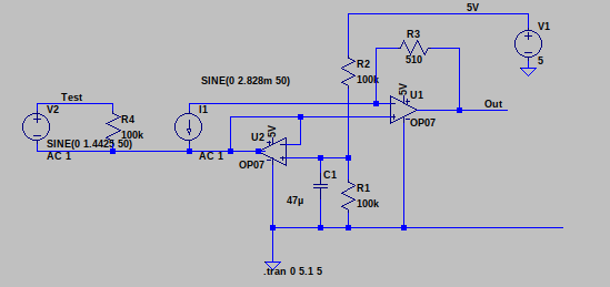
I’ve been looking at this configuration, no burden for the c.t. as it drives straight into a virtual earth. It’s not optimised yet, but it looks promising. The op.amp shows a phase error of -0.1° (-6’) at 50 Hz, which compares well with the 20’ from the c.t. itself, and seems OK to me.
Making the resistors equal is one way to achieve the result, but it’s actually - when you write out the equation for the gain of that stage and do the maths - the ratio that needs to be the same. So adjusting just one out of the 4 is good enough.
Yes, you must stay within the common-mode range of the op.amp’s inputs.
These were the different results from adjusting the amplitude potentiometer, which, clearly can also be used to set a phase shift, which is good to know.
My module might be different for some reason. Who knows! It’s only a single sample.
It’s also a bit noisy, which is something mentioned before by another.
That’s what I thought. In which case as my generator can go to higher voltages I’ll have to drop the aproach for AC current monitoring. I was hoping to avoid the ACS712 or similar but may have no choice. Technically the generator I have is fixed current variable voltage (aren’t they all?), so ideally I shouldn’t need to monitor the current. In reality perhaps it differs a bit by frequency/load (no idea).
Or arrange that the difference in voltage between the place where you monitor the current and the op.amp’s ground reference is within the acceptable range, then if necessary level-shift the op.amp’s output.
My problem is I don’t know what the overall scheme of things looks like, so I can’t step back and have an overall view.
My brain is still struggling to accept the previous without the external supply having a ground reference. To better understand I drew the current loops and so to make a loop for the external supply the comparator must internally have some minor current connection to the pos and ground supplies.
Let’s go over the ground again, because I’ve never managed to tie together all the pieces.
You have some sort of generator, and you want to measure its output voltage and current. It’s supplying a load via a rectifier, and one side of the load is grounded. What do you want to measure about the load? I think you’ve said that one side must be grounded?
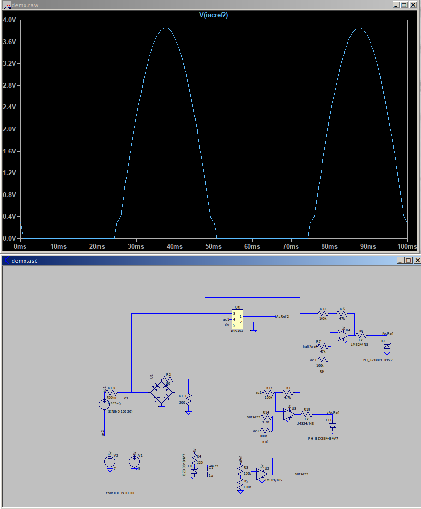
If you can limit the generator shunt voltage to 80 V absolute maximum, it looks as if the Texas INA193 would give you the generator current.
In theory, you can use the same differential amplifier - ground referenced - and keep the voltages on the input pins within the limits specified by your op.amp (i.e the supply voltage). The practical problem is getting and maintaining the balance condition so that the common-mode voltage is adequately rejected. This is where a specialist device that guarantees that rejection will be advantageous.
you have a power source, 0-100v, inductive and saturates, max about 10W, generator so fixed current at ~500mA. Variable frequency 5-200Hz. Measure the power being delivered and the phase delta between voltage/current.
there’s something in the middle like a buck, you have no control over it. It may do phase correction. It outputs into a load which you can control. Measure the power being delivered into this load.
From this efficiency and phase optimisation can be determined.
I’m using a Arduino Mega at least to begin with and since it’s tasked with other things and the CPU and RAM is limited it is best not to introduce phase errors, hence the appeal of non-isolated techniques.
80V shouldn’t happen in almost all situations, I’d be happy to shunt a little before that, so the INA193 may fit the bill!