What is the source of the voltage you’re trying to measure?
This is the transformer’s data sheet that I have seen, where it suggests an OP07:
http://www.interplus-industry.fr/index.php?option=com_content&view=article&id=52&Itemid=173&lang=en
What is the source of the voltage you’re trying to measure?
This is the transformer’s data sheet that I have seen, where it suggests an OP07:
http://www.interplus-industry.fr/index.php?option=com_content&view=article&id=52&Itemid=173&lang=en
It’s a generator, inductive.
So phase changes also based on resistance if the phase < 20d according to the datasheet, then corrected by the op-amp with the CR.
As I’m dealing with variable speed I’m thinking then the op-amp has no purpose and I’ll have to measure the phase for varying frequencies and correct in software (no idea how but will get to that later).
The main reason for using a transformer is to provide galvanic isolation from the mains, because both line and neutral conductors are considered to be live.
As the voltage is not too great, 100 V, and provided that it’s earthed somewhere, why not use a differential input op.amp? or even an ADC with a differential input, with a suitable resistive divider network on the inputs? Plus some protection against spikes. As long as you use several resistors in series to minimise the danger should one go short-circuit, a total resistance of 100 kΩ or so would protect you from electric shock, given that the input terminals and these components would be shielded.
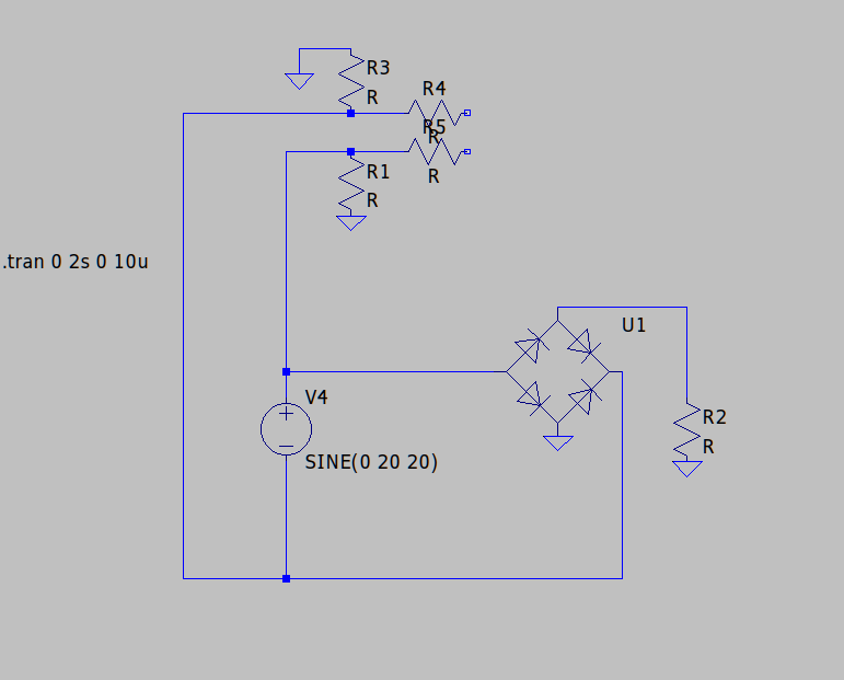
The reason I didn’t initially consider this is in this approach one of the AC lines is normally attached to ground but in my use-case the same AC line is going through a bridge rectifier one output forms the common ground. A diagram might explain what I mean…
What’s R2 there for - earth fault detection? And do you really mean those diodes like that?
That should be OK provided the CMRR is good. You might get some weird waveforms looking at each input individually if there is an earth fault, but the difference should be what you’re looking for.
No R2 is a load. The bridge and load will be an auxiliary circuit (which I have no control over).
The thing is, without isolation I can’t see a means to measure the AC without being affected by the auxiliary circuit as this is what is providing the ground, so the measurement is always affected by the diode voltage drop.
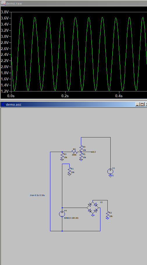
For example can see here the voltage isn’t balanced around the mid-point. Perhaps the way to go about this is to connect the auxiliary, sample the mid-point when the AC is off and use the delta from Vdd/2 in the ADC calculations. I think this would work, so long as the auxiliary circuit doesn’t change the characteristics of the grounding diode (i.e diode heats up, mosfet active rectification)…
Edit - worked it a bit and managed to eliminate the loads effect on the read.
Edit 2 - wrong, change voltage and it fails.
What do you want to measure - the voltage at which points? Can you put labels on the diagram please?
Voltage across V4
PS) I messed the diodes up, should be rotated 90 degrees.
So, the diode bridge feeds rectified a.c. to R2. R11 represents the resistance of the wiring, and everything else are your suggestions for the measuring circuit?
Yes that’s it. In addition there is voltage/current monitoring through the load at R2. V1 doesn’t derive power from the source but it has to have a common ground if it’s not isolated, so the loads diodes always come into play (unless bypassed by some sckottys but either way it can’t be as accurate as isolation. Won’t have the phase issue though…
I’ve got it to a reasonable level by playing with the resistors. It will need a voltage follower now.
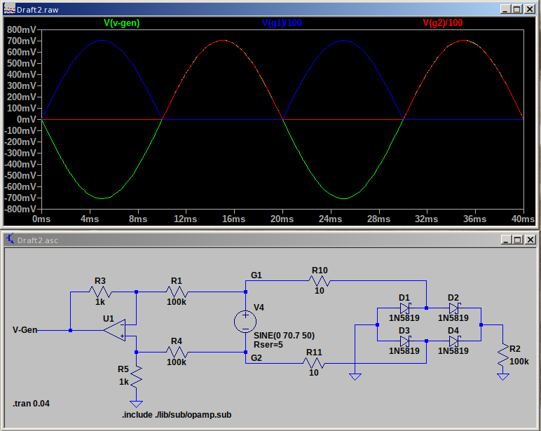
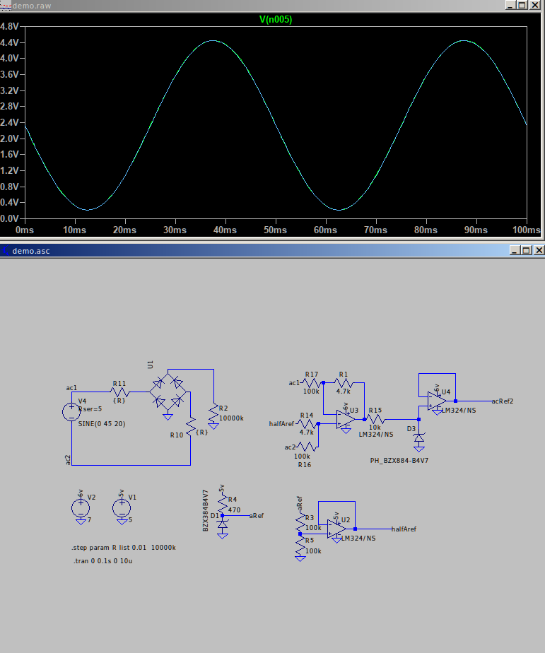
What I had in mind is something like this. The generator (V4) is 50 V rms (70.7 V amplitude), and the differential amplifier U1 has a gain of 0.01, giving a peak-peak output (green trace) of 1.414 V. It matches exactly the two legs of the generator voltage G1 & G2 - (when both are divided by 100 and the former is inverted, as you would expect).
If the ADC input is unipolar, then the op-amp “ground ref” to R5 needs to be at half the reference voltage.
Obviously, I don’t know your ADC input voltage range, you adjust the op-amp gain to suit according to the maximum generator voltage you expect.
There’s no a.c. coupling, so it should be good from d.c. to the op.amp’s limits - which will be well in excess of 20 Hz.
Only problem is the level differs based on the loads rectification circuit.
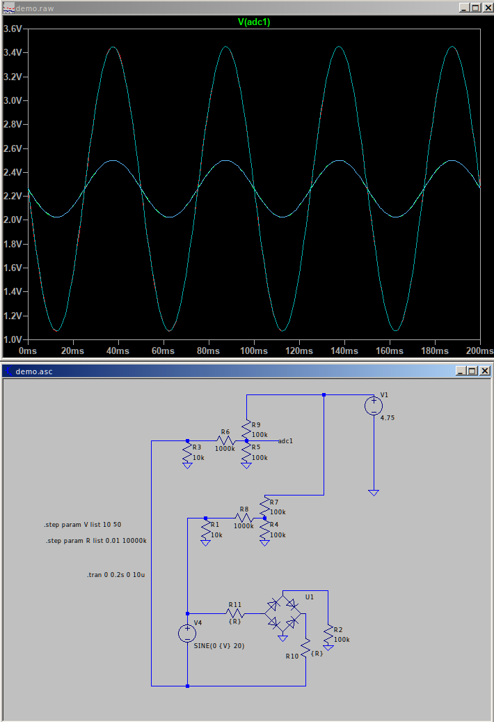
My version, the resistances are so high it’s happy to use the 10k’s regardless of the loads diodes. Upside is it’s load dependant. Downside is it’s consuming a little source current. I’m also wondering what happens when I have difficulty finding resistors perfectly matched for each side. 
I don’t understand what you’re thinking with some of those components and their placement.
Can you explain again what the diode bridge and R2 is? As drawn, when the generator output is positive, the +ve end is clamped 0.65 V above GND by a diode, the -ve end swings to -56 V and + 72 V peak, with the current limited by the diode voltage drop, cable resistance and the generator’s internal resistance. When the generator output is negative, the diodes block all current flow. Either way, effectively no current flows in R2 - or rather, it’s the measuring circuit’s loading resistance and grounds that provide the only path for current to flow in R2.
A few more points that puzzle me:
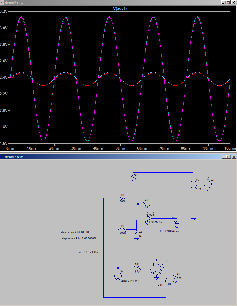
In the top circuit, what is D1 doing? Only clipping the op.amp output at 0.65 V or thereabouts. Why?
And what is V1 & R5 doing? If you want to offset the output, by far the best way is to lift the end of R4 that’s grounded up to 1.65 V (or 2.5 V, depending on the ADC input voltage range), rather than squirting current into one input.
In the bottom picture, what are R1 & R3 intended to do? They are only loading the generator, not contributing to the measurement circuit in any way.
An AC power supply powers a device which outputs to a load, for example a USB power converter to a phone. Find:
A) Input voltage
B) Input current
C) Output voltage
D) Output current
The focus here is A.
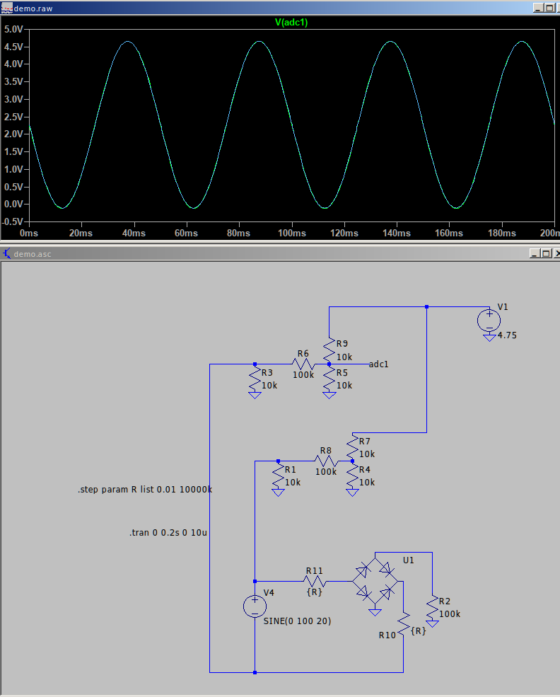
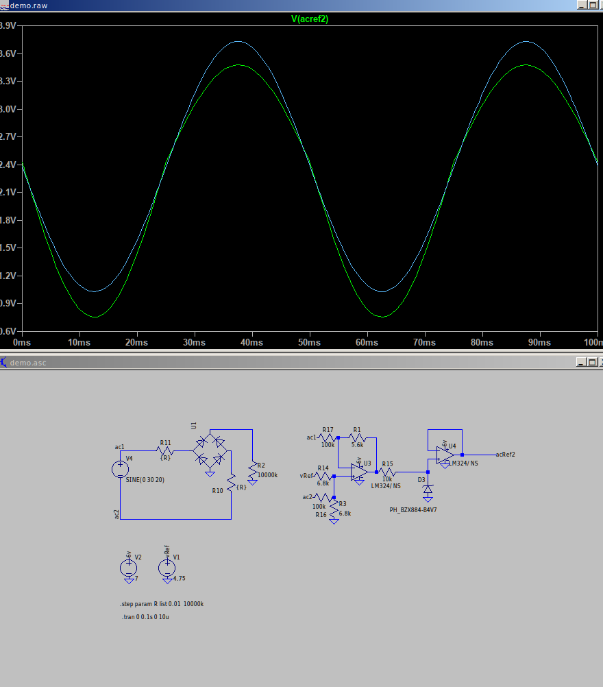
So you have no control over the device being powered or the load it puts into, represented by the diodes and R2. You can’t assume what diodes are being used. The two resistor R10 and R11 are merely switching the device in and out (via very low resistance and very high resistance by way of the .step Param R list. This is to prove that the AC voltage measurement value is not skewed by the device being there (even if it’s taking zero power).
In my case I set the resistors to clip the signal at about 50V AC input, just because I’d not interested in voltage above that and would prefer the resolution at the lower end.
Ultimately why does mine work? If the device isn’t there (switched out) there is no means to reach ground so nothing can be measured. This is the point in R1 and R3. The combined impedance of R5/R6/R9 is so high that R1/R3 exhibit very little voltage drop, thus they act like an ideal diode.
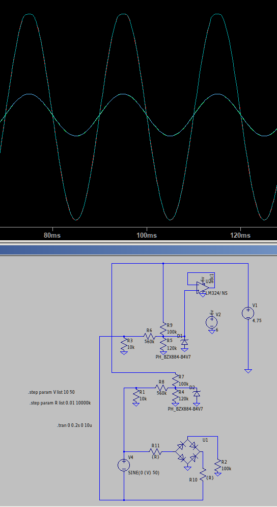
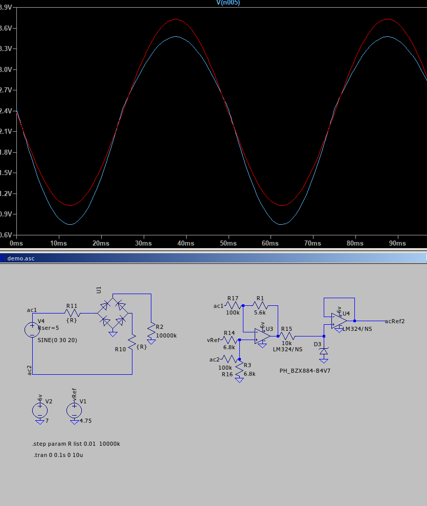
If you make R10/R11 on yours the same with the .step param R command, so you get an AB test, you’ll see that yours will fail when the device is removed.
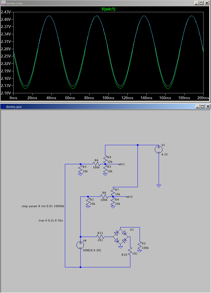
I somehow reverted the bridge diode and didn’t spot it, so my work is wrong. Here’s yours. I’m back to thinking it’s impossible without isolation.
Yes, but…
The source will have some internal impedance, no matter how “good” it is as a voltage source. Therefore the load will affect the measurement. If it’s negligible, that’s a different question. If the effect is too small to measure, that’s also a different question.
I don’t understand that. resistors will load the generator and reduce the voltage - proportionately, they won’t do what I understand as clipping.
From what you’ve been writing about how things seem to change and you can’t explain it, I’m afraid I rather think it doesn’t.
That’s not true. The exact analogue of that is you can take a meter to a battery and measure the voltage of it with absolutely no ground connection there at all. Why should this situation be any different? In fact, there is no such thing as absolute voltage. Voltage is always a difference between two points. It’s normal practice to measure with respect to ground, but that’s only a convention. In your car, you measure with respect to the body shell. There might be some voltage between that and the ground it’s standing on. (It will be small due to the conductivity of the tyres, but that’s a different story.)
I think you are on the wrong track there. R1 & R3 together mean that the generator voltage is centred about ground, so the voltage on the two legs is symmetrical about ground. At the instant the voltage is (say) 50 V, the + leg will be at +5 V with respect to ground, and the - leg will be at -25 V. R3, R5 and R6 can be lumped together as a single resistor, with a value of 9.84 kΩ, and you wouldn’t know the difference. And a resistor will never act like a diode.
I think it is. That’s what the differential op.amp is there for - the two inputs measure each leg with respect to the common voltage (1.65 V in this case) and it computes the difference between the two legs. That’s what I understand you’re interested in.
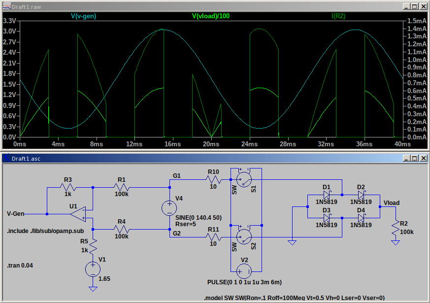
So, as you’re worried about the loading effect on the generator, I’ve put two genuine switches in series, and so that you can see the effect on the generator voltage, I’ve driven them on for 3 ms and off for 3 ms.
To make the generator just a bit more realistic, I’ve given it a 5 Ω source resistance. It’s only when I make the load resistance 100 Ω (one thousandth the value you have, drawing 400 mA), that I can see a slight step in V-Gen.
Which is exactly as I’d expect.
When the switches disconnect I was thinking the only loop is around R1 and R4. I’m forgetting that the neg pin has feedback so there is a loop there to get to +V. I’ve learned something, thanks.
Strangely I can not replicate your work. The layout is the same other than resistances-switches and yet I see a distinct change in the read. Now the delta is the same so once the RMS calculation is done it won’t make any difference, but I am curious to see how there’s no affect in your sim.
No it’s not. You’re offsetting the op.amp output by injecting a current into the NI input. I’m lifting the bottom end of it’s input divider by a voltage. They aren’t the same thing. You must have missed that earlier.:
I see. In reality the ref has impedance as it’s half the aRef fed into the MCU. Sorted and looking good.
I think I’ll kill two birds with one stone and try to do something similar for the current using a sense resistor.
Thanks A lot Sir.
Your detailed analysis helped me in solving my issue. i had to develop two energy meters and both of them are working well within acceptable error range.
so for anyone else trying to use ZMPT Module to measure Ac line voltage may find my calibration values to be helpful in making the emonlib work perfectly with ZMPT module.
all i did was to adjust the PHASECAL and VOLT_CAL values. i didn’t had an oscilloscope or any other means of visualizing the waveforms and finding the exact phase differnce and logically alter these values. so i relied on alter and test methodology and kept changing both these values in small steps and kept testing with an incandescent bulb - considering it to be a resistive load.
my final values were:
VOLT_CAL was 730
and PHASECAL was -0.3
for these values the resisitive load power factor was 0.96 to 0.98. i then used an auto-transformer in series with a 100W bulb as an inductive load. The greater the inductance the lower the power factor was (as it should be). i took alot of readings and the came out to be quite close to the actual readings.
Therefore if you are using a ZMPT to calculate line voltage to be used with emonlib then all you have to do is to adjust the calibration values. i have provided both the values that are working fine with me. if these values didnt work for you than you may consider changing them slightly.
i used SCT013 (30 A) sensor for measuring the current. i am using arduino nano.
my final line in my code looked like this…
emon1.voltage(0, 730, -0.3); // Voltage: input pin, calibration, phase_shift
i hope this would help others trying to use ZMPT101B instead of an Ac adapter to measure ac line voltage.