That makes no mention of having to ground the load, so why do so? Measure everything from the grounded side of the generator instead.
I think this infers the device and it’s load are connected to a grounded generator side as well, which they probably aren’t.
This might be useful, the LMP8603.
lmp8603.pdf (2.0 MB)
Probably a final suggestion, because I’m running out of ideas:
If you can’t measure the generator current with sufficient accuracy with the measurement side grounded, then you need two separate measurement ‘devices’, one for the generator and one for the load.
The generator’s will be measuring generator current (effectively low side) and voltage, comprising two ADC channels all isolated with a separate power supply.
Do roughly the same with the load, measure its current and voltage, ground referenced.
Optically couple the generator’s measurements (digitised) into the processor that’s grounded and processing the load measurements, and process all the measurements as required.
I did think about that but framing the reads with the others will be more troublesome.
I’ve won with the AC voltage monitoring. How much phase does an ACS712 or similar introduce? It may be my best option, if a little inaccurate.
They’re good those ACS7xx’s, it’d simplify your current monitoring a lot. I don’t know about phase but it wouldn’t be more than 5˚ I’d guess… Their bandwidth should be good for your 200Hz too.
There’s this in the shop, I could chop the price down by now as there’s quite a few PCBs sitting around, and a few ACS… Or if you wanted to take the PCB and source your own ACS, I could arrange that.
Dan - I need a little more integration, sorry!
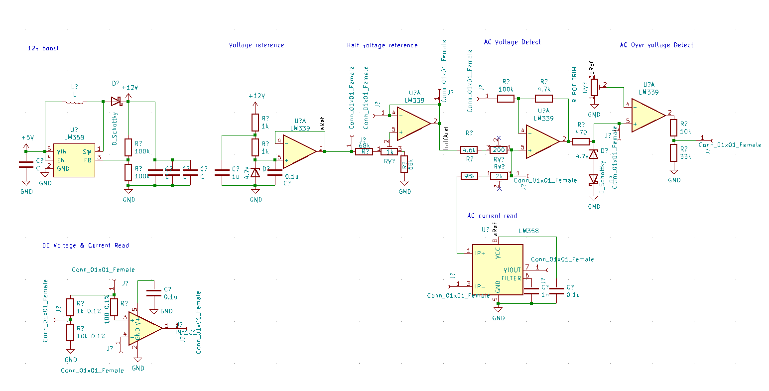
I spend a few hours and came up with this. Most is already simulated in LTSpice. Ignore the resistor values, first chip is MT3540 etc, but the approach seems ok - any feedback much appreciated as I’ll run a few off next week.
Points -
- The MCU should be getting high impedance reads which hardly change due to the filtering and op-amp followers.
- Minimal phase other than the ACS712.
- I’m aiming for a 50v AC max with an over-voltage alert. If there’s a better way of limiting the voltage out of the third op-amp I’d be interested to know it.
- Hopefully the approach with the resistor POT’s is correct to balance the third op-amp.
I have a prototype board up and running. One question though is how to balance the 100k and 4.7k resistors, that is, what the output should be that I am aiming for.
I propose for the 100k if I feed an identical signal into AC1 & AC2 then the POT should balance so that halfAref = output.
Then the same signal is fet into AC1 and AC2 separately and the second POT is adjusted so the swing on the output is equal.
