i want to use a ZMPT101b for measuring the Mains voltage instead of using a 9v Ac-Ac adapter. but i could not find any circuit diagram or guide about how to connect ZMPT sensor to arduino in order to ensure proper power factor and other calculations.
Please guide me in the right direction
google seam to be your friend
And if that fails, try searching here. A similar question has been asked and answered and discussed numerous times.
I put together this circuit and it worked very well. I would put an extra 10k between the Neutral and transformer nowadays… The two opamps of the ones I tried had a 3Mhz and 5MHz bandwidth, and were both rail-to-rail.
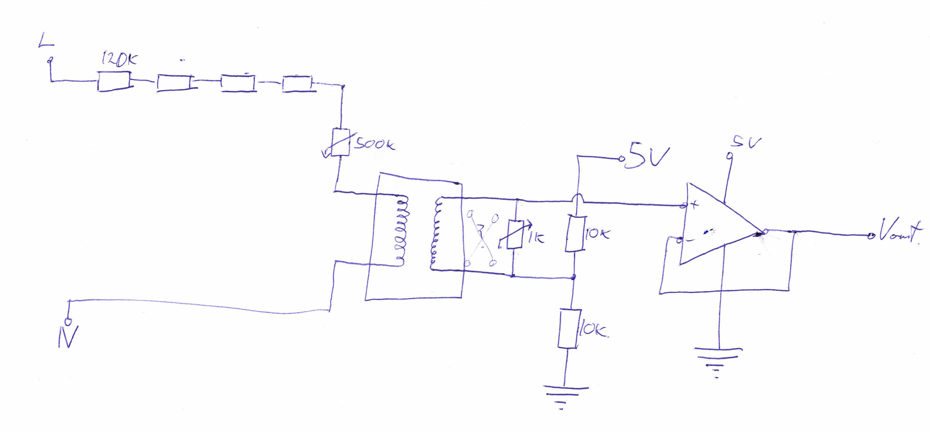
The X in the middle by the transformer is not a skull and crossbones, it’s to indicate swapping the wires to invert the phase… I used a 1k potentiometer to play around with a variable burden size…
I’ve got an image of the protoboard I soldered up somewhere…
i have already measured the values and correctly calibrated ZMPT and SCT sensors seperately and correctly measured apparent power. but when i used emonlib to measure power factor it gave a laging power factor of 0.8 for pure resisitve load. both ZMPT and SCT sensors gave very accurate readings when i measured current and voltage seperately without using emonlib.
what might have caused the problem?
in my views i think that ZMPT needs some extra components for being compatible with the emonlib without making any changes. right?
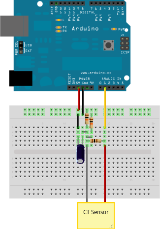
i used the following circuit diagram for connecting ct sensor.
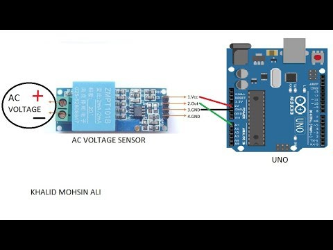
and connected the ZMPT directly to arduino using the following schematic.
please refer to the new comment i just added below on this post
please refer to the recent comment i just poste below
Most likely it is the almost complete absence of phase error in the ZMPT101B.
Did you follow the calibration procedure in ‘Learn’ regarding setting the phase compensation? You’re likely to need a value quite a way off the default setting. That’s because there’s no such thing as absolute phase, it’s the difference between the phase errors of the c.t. and v.t. that counts.
I’m afraid pictures of an Arduino don’t help me - I can’t read what the terminal names are. If your ZMPT101B module is the same as the one I have a circuit diagram for, the output is biased to 0.5 VCC, so it should be able to be connected directly to the Arduino input (assuming a 5 V Arduino).
The ZMPT101B within that module, with filters and opamp, does create a significant lag. I desoldered the transformer and built the simpler circuit above instead, which performed better.
You might be able to add capacitance, or an RC filter, to the CT circuit to bring it back in line with the ZMPT module as it stands.
Blockquote
what exacctly is meant by the absence of phase error?
yes i read and applied (did my best) the calibration procedure for phase compensation but it was unable to completely solve the problem. the error in power factor reduced but didnt vanished completely. i vaired the PHASECAL value from 0 to 3.
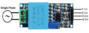
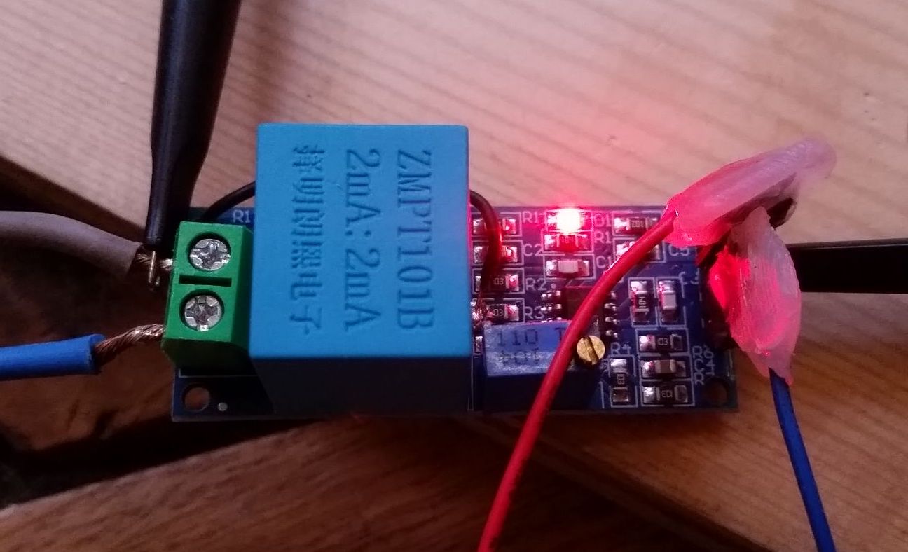
yes, my module can be directly connected to arduino and it produced the expected results without much error. for further clarity im attaching an image of my zmpt sensor…
@Robert.Wall I think we need to take a closer look at this transformer within the context of the complete module as seen above.
I’ve several of these ZMPT101B now, one of which I might reassemble the complete module with. I’ll wire it up to the scope to see what this phase error is like.
it would be a great help for this amazing community. please share your findings with me as well. m sure it would help me alot…
All transformers have a phase error - meaning the input and output waveforms are not quite in step. There are three factors that mean the Arduino gets the power factor wrong, and it needs to compensate for the combined effect of all three. They are the phase errors of the two transformers, plus the time difference between reading the two readings. Because the ZMPT has a tiny phase error (compared against the normal a.c. adapter - it’s 0.5° against about 6°), you’ve run out of range on PHASECAL.
I’m afraid the answer will be that you will need to modify your copy of emonLib to either swap the order of the voltage and current reading, or maybe even store one of the readings to manipulate the time delay (which is equivalent to a phase shift).
I’m going to need some time to work out what you might need to do.
So the approximate phase error at your approx. power factor of 0.8 will be cos⁻¹ 0.8 = 36.9º
As Robert points out your power factor will be the result of a combination of factors.
I’ve reassembled my ZMPT module:
I had to route a wire around the other side of the pic as one of the vias got pushed out! Far too easily too tut tut tut cheap board.
Connected to a 5V supply regulated from a car battery:
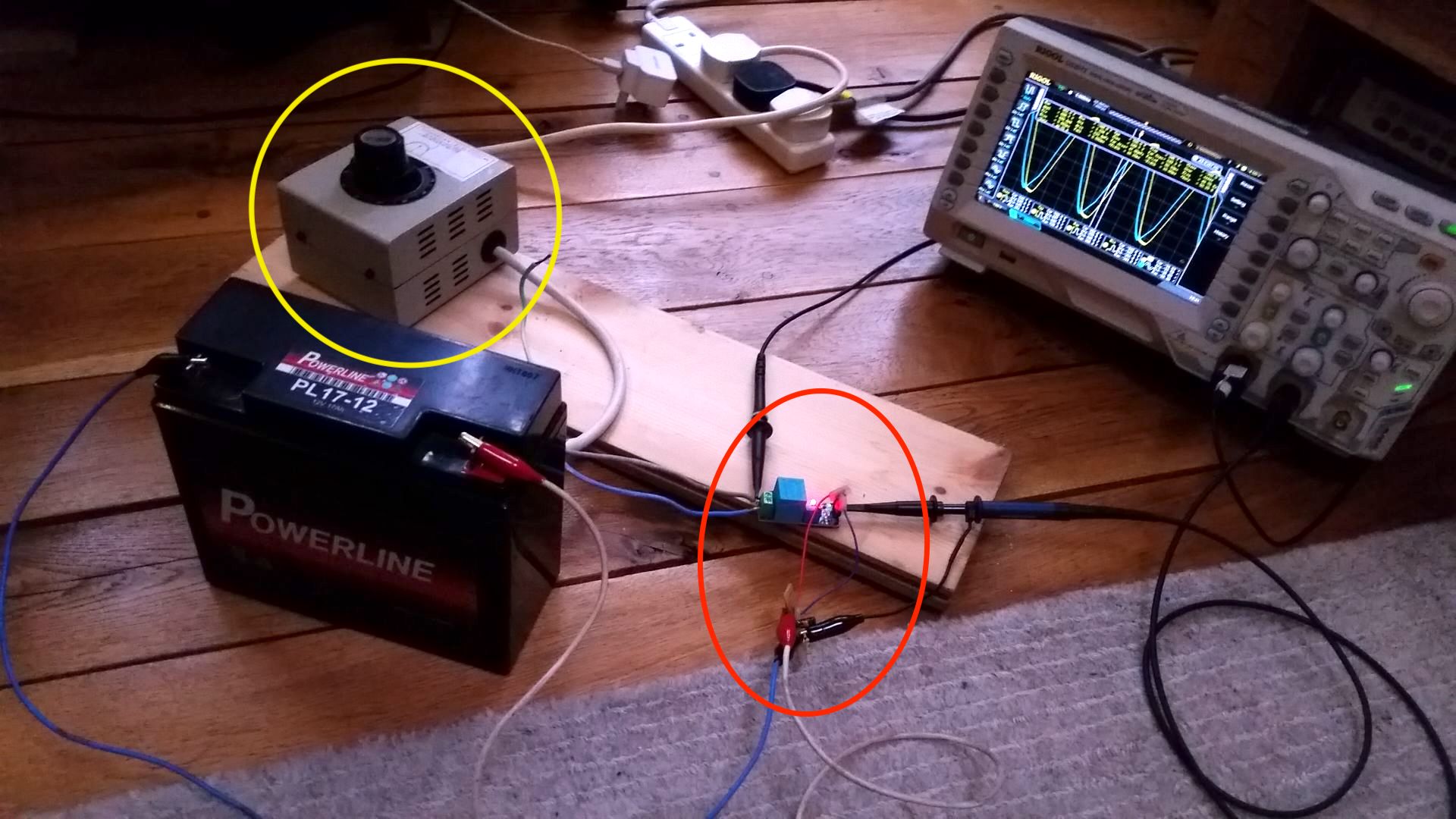
- yellow oval : Variac for voltage adjustment
and isolation. - red oval : the module and 5V regulator
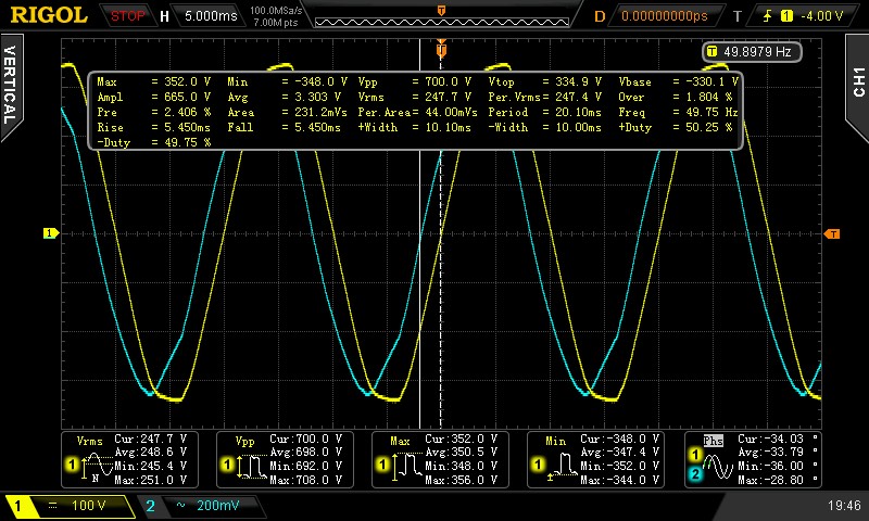
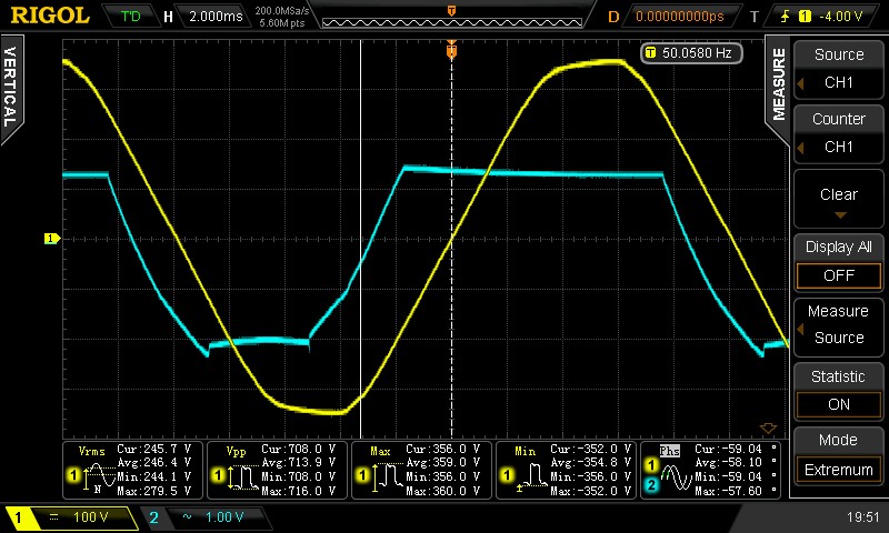
ZMPT101B against Line Voltage, phase error shown at bottom right. Phase difference -33.79º Average. I’m taking about 30 seconds averaging and then stopping the scope…
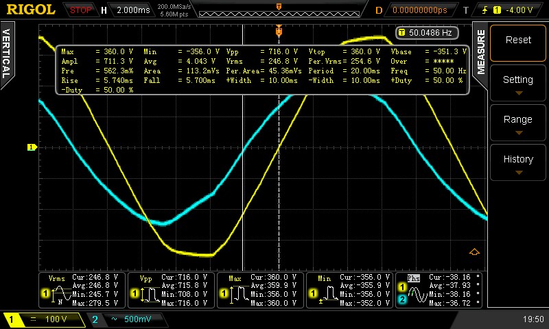
Amplitude adjustment screw on the ZMPT101B turned as high as it’ll go without clipping. Phase difference -37.93º Average.
Amplitude adjustment screw adjusted further!
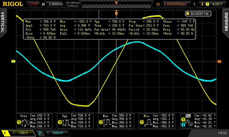
Turning the screw right down. Approx 300mV peak-to-peak output signal. Phase error -43.39º Average.
The phase error seems relatively consistent over the voltage range too. 0.5º difference between 110Vrms and 240Vrms input.
Oh no it isn’t - adjustment, yes. But a Variac is an auto-transformer. It does NOT provide isolation.
Ah, true! I just measured the input/output impedance and it’s not at all isolated on either the Line or Neutral! Darn!
I need to get hold of a decent 1:1 isolation transformer.
I’ve made some measurements on emonLib and these give you all the information you need to modify your version of emonLib to suit the ZMPT101B.
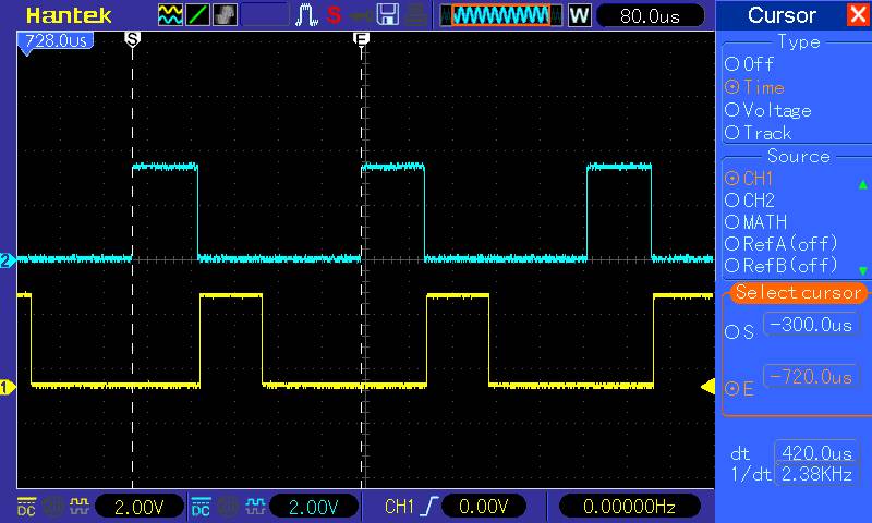
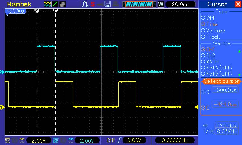
I modified emonLib to write to two digital outputs and recorded the waveform. The blue trace goes high immediately before the line
sampleV = analogRead(inPinV);
and goes low immediately after, and the yellow trace does the same for the line
sampleI = analogRead(inPinI);
These two images show that a pair of readings is taken every 420 µs, and the time between reading voltage and current is 124 µs. Driving the digital outputs took 4.8 µs each, so say 400 µs and 120 µs.
The other things you need to know are, the phase error of the ZMPT101B is claimed to be less than 20’ - so you can probably neglect that, and the phase error for the YHDC SCT-013-000 can be got from the test report in ‘Learn’ - it varies with the current and the burden resistor, so you’ll need to estimate the value based on the conditions you use it in. If you use a different c.t, you need to check its data sheet. It is phase lead, which means the output appears to lead - come before - the input. You must convert this error in degrees to a time, you know 360° is equivalent to 1 cycle of mains, which is 20 ms (or 16.67 ms in the 60 Hz world).
You can look at the code in emonLib to check the details, the way to work through the problem is you look at 2 pairs of voltage and current readings. Mark their positions on a scale of time on a sheet of paper. These are the times that the readings arrived in emonLib. Now mark where the voltage wave was measured - because the error is very small, you can say it happened at the same time as the voltage reading was made. Do the same with the current wave, but this is offset later by the phase error.
Now to relate this to PHASECAL. One unit of PHASECAL is the time between a pair of readings - 400 µs . PHASECAL calculates a new value for voltage based on interpolation or extrapolation using the last voltage reading and the present voltage reading. A value of 0 uses the last voltage sample, a value of 1 uses this voltage sample, the idea being to choose a value (and you can have negative values) so that the adjusted (“phase shifted”) voltage coincides exactly with the current sample.
It is a bad idea to have a value of PHASECAL too far outside the range 0 - 1, to keep it inside that range you can swap the order of readings (i.e. read the current first, then the voltage) or you can store the sample before the last one and use that in the calculation.
There is an explanation of the PHASECAL algorithm in the ‘Learn’ section.
Hi all,
In have a related question which fits in with this thread. In my case I’m to measure a source of varying frequency and voltage (0-200Hz, 0-100V).
I’d like to minimise phase correction and noise. It seems this common ZMPT101B module (which I have) adds both at the expense of minimal current draw. What is the standard recommendation? I like using the op-amp as a pure voltage follower as it doesn’t induce phase, though I’m also not really sure if it’s needed given MCU ADC pins tend to perform well with 10k impedance.
Welcome to the OEM forum, Andrew.
I’ve no experience of using the module, I’ve only looked at the data sheet. Other than the choice of op.amp, there’s no real reason for it to be excessively noisy, so one obvious question is, is the noise generated by the op.amp, or is it coming in via the supply?
I don’t know what’s inside your particular module, one circuit diagram I’ve seen has a pair of LM358’s with a variable attenuator between them, but the resistances don’t look wrong from a noise point of view.
The ZMPT101B Transformer data sheet suggests an OP7 in virtual earth mode, with the transformer secondary feeding directly into the virtual earth. This will probably cost rather more in terms of supply current, as the op.amp needs to source and sink the transformers secondary current. I haven’t done the maths for a noise calculation on either configuration, so I can’t advise you.
The major point though is - you can’t get 0 Hz through a transformer. I know people who’ve tried, it’s usually accompanied by a nasty burning smell. That’s not likely in this case as it’s a c.t., but the transformer data sheet does specify the frequency range as 50 - 60 Hz. Though I’d be more inclined to expect usable output above 60 Hz, it might not go to 200 Hz without significant phase and amplitude errors, and I certainly wouldn’t expect it to go very much below 50 Hz. How far below it will go depends on how much iron there is in it, i.e. the core’s cross-section.
I think my first move would be to establish over what frequency range you get an acceptable accuracy in amplitude. If it’s “good enough”, then it will be worth checking the phase error.
Yes I should be a little more accurate, the realistic frequency floor is 10Hz, and the typical voltage level is around 6-10V. It’s inductive hence with no load it can rise to 100V though I’m only really interested in anything below 40V, so above could be left to clip.
I thought a 1:1 transformer wouldn’t give any phase error as the inductances being equal would cancel each other out, with phase introduced by the capacitance on the output side and the op-amps bandwidth. Although the MCU’s ADC technically adds phase (sampling capacitor) I suspect it is minimal - if I’m wrong that would explain the benefit of the op-amp.
I found the module in question to be extremely noisy until I added a 100uF capacitor on the input. I also added a filtered 4.7v supply but couldn’t get the output to swing above 700/1023 of the 4.7v supply (also used for the MCU Aref) without clipping when I upped the resistor across the transformer. I’ve now ripped it apart ready to DIY.
So the question is whether to op-amp or not for the circuit Daniel posted. The thevenin impedance equivalent presented to the ADC indicates it would have little benefit for the tiny value of the MCU’s sampling capacitor.

Not related, I was hoping to use this communities Arduino code to handle the phase calculations but it’s a one-shot pony. I’m doing other stuff like RPM calculations, screen output and so on so having to write an interrupt based approach. I’d be interested to see if anyone’s already done something like this already.