You’re welcome Sam. You make it easy to help you, with clear questions/answers, good graphs and frequent updates and your original post gives lots of great background info. This thread will help others in the future. The NIBE systems are well-engineered and very highly configurable so I’m sure you’ll get a great outcome; you’re well on the way already.
Yep; that’s curve #12 which sounds far too high for what you’ve said about your heat loss. I’m on #5 (albeit in a nearly-Passivhaus) and I think the factory default is #9. I’d put it on #10 and be prepared to drop it some more if it’s still too warm.
That will definitely be a worthwhile addition. There’s a configuration setting which determines how much ‘influence’ the indoor temperature has on the WC calculated S1 Target, so it’s a no-regrets addition.
My experience is that the best location is as close to the middle of the house as possible. Mine’s on the 1st floor landing (in a 3-storey house) which works well; that only has a North-facing window. You want to avoid too much direct influence on the sensor from the passive solar gain. I think I’d be inclined to put yours downstairs. You can always have the UFH switch off via the room stat when the upstairs is getting solar gain. Otherwise I suspect the downstairs might not get warm enough (but depends on whether you prefer the bedrooms cooler anyway).
Do you have a “speed in wait mode” option at 5.11.1.2? I believe “wait mode’” = standby, i.e. compressor off.
No I didn’t have that option available, I do now so have made the change as you suggest. Sometimes reading the manual does indeed help…I had the “Operating mode” set to intermittent rather than auto and therefore the option was not available to me on the screen
today I managed to drop the curve down to 7 without any noticeable discomfort in the house, if anything it was still a little warmer than necessary. The off periods between cycles seemed to be around 1.5 hours which is better than yesterday and today is also colder outside. The changes made were to reduce the curve down to 7 and run the charge pump at 10% in “wait” mode.
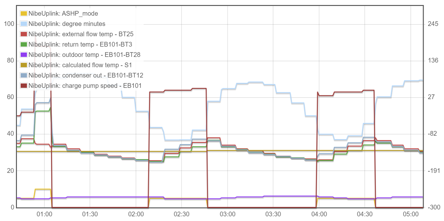
I have had lots of problems with the uplink API calls today, a lot of timeouts so my available data is limited but the behaviour today was generally in line with this snapshot
One thing I notice a lot after a period of heating, is a spell of DHW for a short period. Is this normal Nibe behaviour? An example of this is shown at 1500 where the ASHP_mode jumps up from 5 to 10 (this signal is my own one determined from the API to show the operating mode of the ASHP 0=off 5 = heating 10 = DHW). At this time there was no direct hot water used in the house so I am not sure why it wants to inject some heat into the cylinder.
Looking good Sam; those graphs are much more ‘normal’ for a NIBE system. Vastly better than a week ago!
My older F1145 doesn’t have a variable-frequency compressor so it’s only ever On or Off; your F2040 has an inverter so I’d expect it to be modulating down and doing more slow-speed-running and less cycling. It’s worth taking a look at the Compressor Curve (probably in menu 5.1.23) to see what that’s set to. Maybe also add Requested Compressor Frequency to one of your graphs (if you don’t have that already) so you can keep an eye on how ‘hard’ its running.
I have my DHW reheat ‘blocked’ on a schedule so it’s only allowed to run overnight (on cheap-rate power) - mainly because I have a solar PV diverter that does most of the hot water via the immersion heater, so I give that chance to do its thing during the daytime. Other NIBE owners seem to get regular DHW runs during the daytime, more like you are describing. What ‘comfort mode’ do you have your DHW set to - Economy? Luxury?
It’s typical behaviour for a NIBE system to do a hot water ‘run’ at the end of a heating ‘run’ (or vice-versa) - but only if it thinks it needs to.
Thank you for all the help as I get towards “normal”. I am not yet seeing this translate into reduced electricity usage but I don’t have any form of baseline to measure against and the weather has taken on a cold snap just as things have started to improve.
I havent got that logged from the API as yet, I will add to my script. In the next few days I am going to fit some energy monitoring (emonTx) to the heat pump circuit and start correlating this against the data from Nibe - this and DHW are probably my next two areas of focus. Longer term I will fit a heat monitor and look at the SCOP too.
I have thought about this as a way to reduce the perhaps unnecessary reheating, I have not been able to understand how to “block” though. Is this option in the settings or does it need external hardware into the controller - I think I recall this from some of my earlier reading on the Nibe systems.
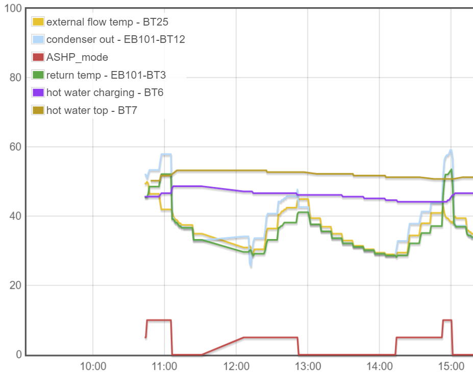
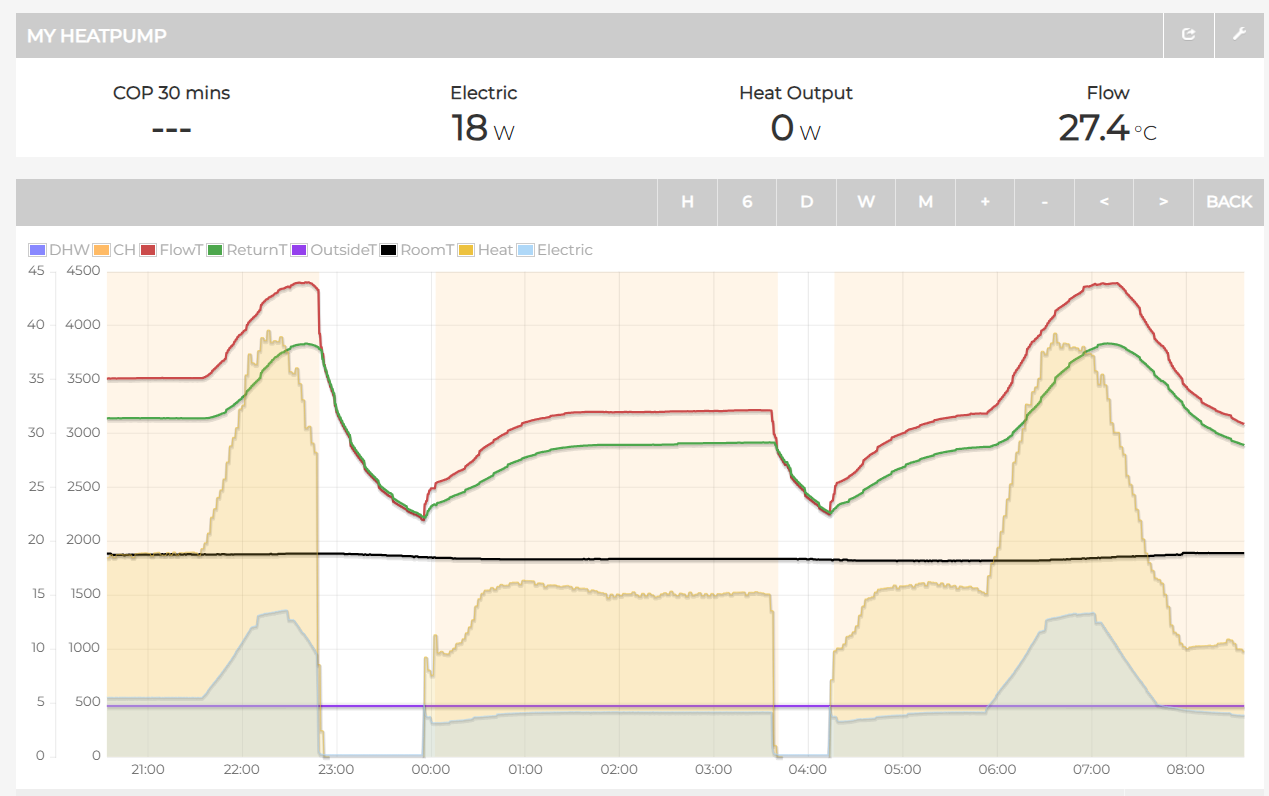
This is what is still confusing me, why it “needs” to do a hot water run. As per the below graph, I am losing temperature in my water cylinder but it isn’t dropping to a level below my lower limit in the settings. My lower limit is 42 degC and upper is 50 degC for Normal comfort (my selected level). On the graph for BT6 the value at just before 1300 is 47.2 and when the ashp starts the recharge BT6 is measuring 44.2, this is above the 42 degC lower limit. It as though the ASHP is “predicting” the lower limit is being reached and starting the cycle whist the ASHP is still up and running.
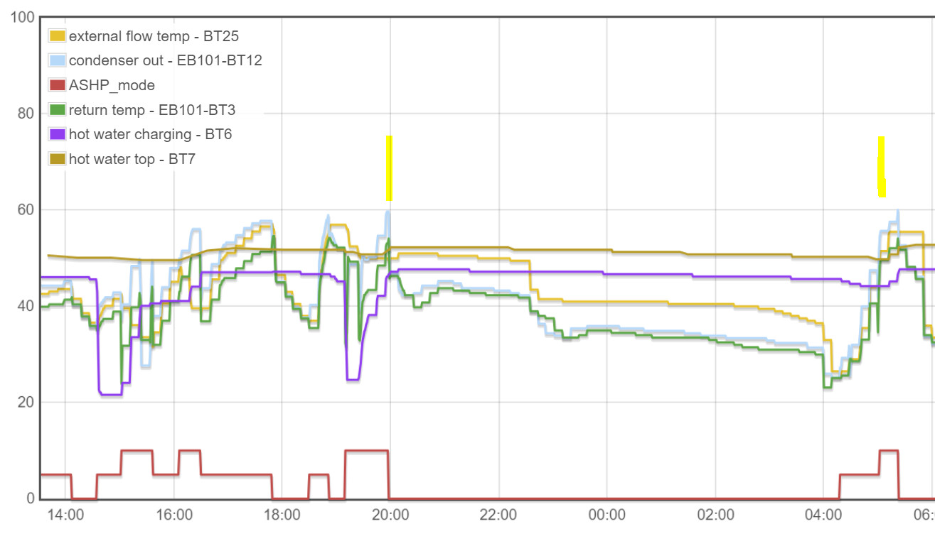
And a final thought, a 3deg drop over less than 2 hours seems too much especially considering there was zero demand for hot water at the time. Looking back at some of my data, I found a period of no ashp activity over night and BT6 is shown to drop just 2 degrees in around 8 hours, but as soon as the ashp / circulating pumps run at 0400 the BT6 decrease accelerates and I see the same reheat at the end of a heating cycle. Again there was no DHW use at this time.
Yep - should be under Hot Water, 2.3 ‘scheduling’. I have mine set ‘off’ from 04:30 - 00:30 every day, so it only kicks in after 00:30 and before 04:30, which means there’s always 50C hot water for the morning. The immersion heater (solar PV divert) thermostat is set closer to 60C so if that has got to temperature the day before the heat pump doesn’t attempt to heat the DHW at all.
Yes; that’s too much, and worth more investigation. My DHW tank was 56.9 at 00:00 then 53.9 at 08:00, so losing 3C in 8 hours (more like your best-case 2C in 8 hours). On complex installations with multiple DHW tanks there have been cases of the CH pump circulation ‘stealing’ heat from the DHW tank coils but based on your schematic there should be no chance of that if the 3-Port Valve is working properly.
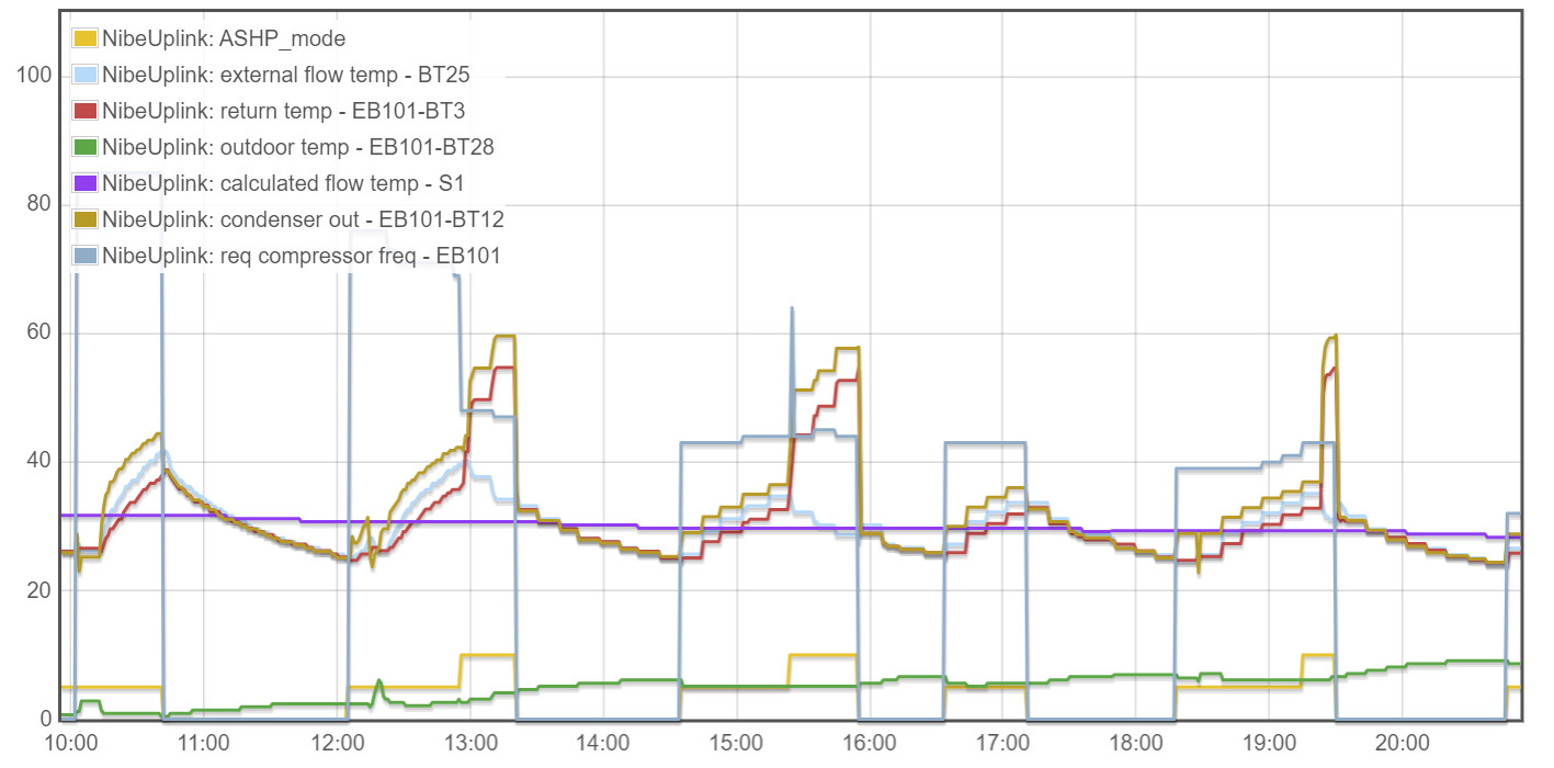
Today I went to curve 5, the house was probably a little on the cool side but not cold. I added compressor frequency, the first two cycles are at a higher duty but then the last 3 are lower. I am not sure why? The only difference I can see is delta T on the first 2 is near 7 deg whereas for the last 3 cycles its down at 4deg.
I am consistently getting the hot water recharge at the end of a heating run so I am now going to focus on that because it doesn’t seem right. I plan to add some probes to the flow and return in/out the hot water cylinder and see what is going on during the heating cycle - this will take a few days to get set up but I will report back any findings.
It’s because of the outdoor temperature, influencing the compressor frequency via the Compressor Curve. The first cycle in particular was at close to freezing, so it picked a higher frequency (speed) than for the later ones. If you can tweak the Compressor Curve down a bit it should run less ‘hard’ (although I’m not sure how much lower than 40% it will be happy to go).
Sounds like a good plan. As Marko pointed out, there may be some thermosyphoning going on which another valve might be help to prevent (either a simple non-return-valve on the Return from the DHW coil, or a two-port valve wired in parallel with the ‘DHW’ position on the 3-port-valve).
Thank you and thank you to @marko for the advice / areas to look at. I will investigate and keep this thread updated to help anyone else with future similar problems that they may see.
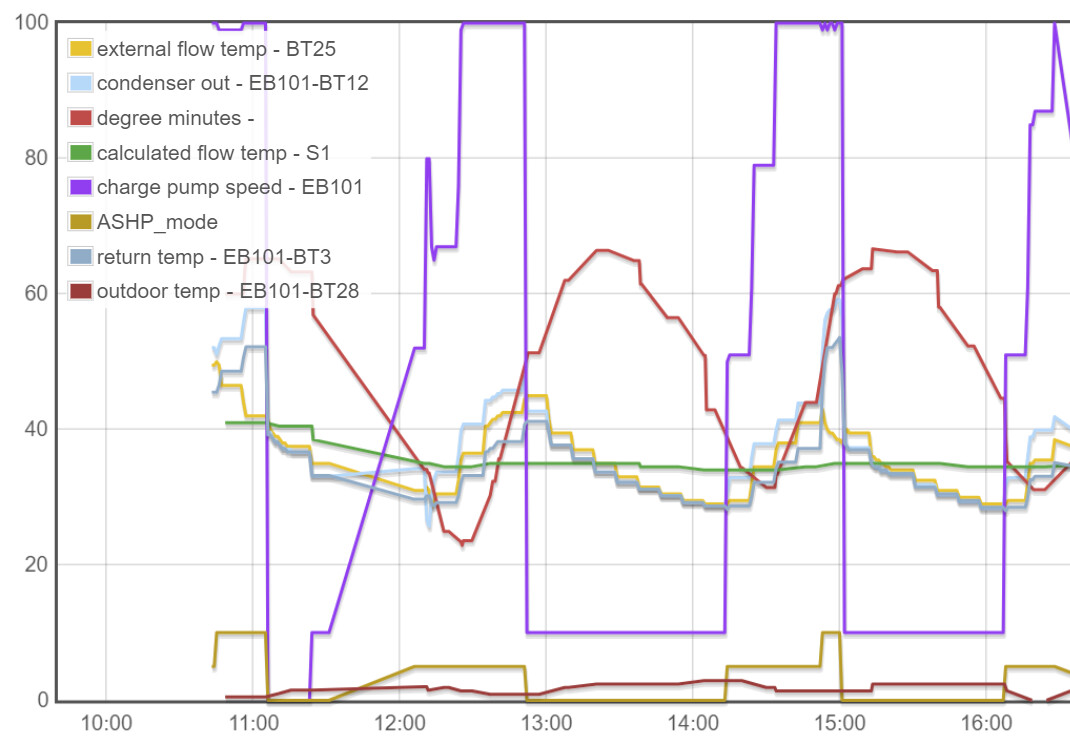
hello again. I am still instrumenting up the hot water tank to determine what is going on with the hot water temperature when the heating is running. In the meantime I have had some stable running and wondered if the following observation was correct and if indeed this is “normal” or best practice.
As per earlier advice, I have switched my buffer tank pump and underfloor pump to run 24/7. When the heating demand is satisfied and the Nibe control system detects this with 0 degree minutes the ASHP shuts down and the ASHP charge pump stops. The buffer pump and underfloor pump are still operating and circulating the previously heated water. I can see from my graphs that the ASHP flow, ASHP return AND the buffer BT25 flow all very quickly converge on the same temperature and there is no dT between them. This suggests to me the water is being pumped outside and is cooling rapidly through the ASHP (which isn’t running). As a result this cooler water circulates through the radiators / UFH and BT25 quickly drops below the target temperature (S1) and the degree minutes go negative, the house hasn’t really cooled down but the ASHP starts again. I have tried running the charge pump in idle mode but if anything this accelerates the effect.
As per my original schematic, is this normal to circulate the heating water (if indeed this is what is happening) through the ASHP when the ASHP is not operating? Or should it just be circulating on the heating side of the buffer tank?
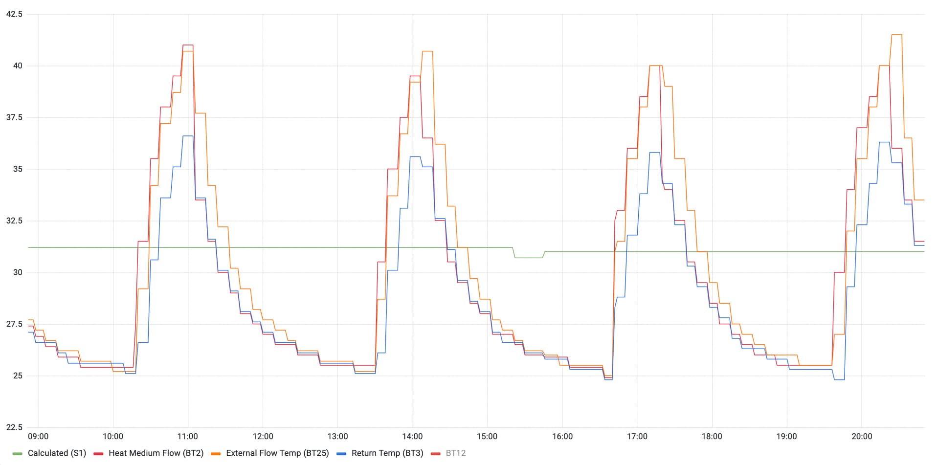
A graph below shows the quick convergence of flow, return and buffer tank until the time the degree minutes hit -60 and the ASHP kicks in again.
Here’s a graph from my system - looks pretty similar to yours, I’d say: BT25 (Orange) stays a couple of degrees higher than Flow (Red) and Return (Blue) but Flow and Return converge as soon as the compressor shuts off.
When the Charge Pump is off, there will be little water moving through the outdoor unit; your other pumps are circulating via the Buffer Tank, which gradually cools. I don’t think you’re seeing the water cooling via the outdoor unit - you’re just seeing the effect of heating the house.
Bear in mind the ‘Degree Minutes’ are just measuring how the actual flow temp (BT12) compares with the target flow temp (S1) over time. The WC logic is trying to make these temperatures average out the same, not answering any ‘call for heat’ or responding to the temperature of the house:
The compressor starts at the configured number of (negative) DMs; sounds like you’re on the default of -60 (I’ve made mine a lot more negative to reduce the number of cycles, since I don’t have a variable-frequency compressor)
The compressor runs until the DMs reaches 0 then shuts off; the residual heat in the system keeps increasing the DMs for a while (but they’re capped at +100)
Once the flow temp goes below the S1 target, the DMs start reducing and the compressor re-starts when it reaches the configured limit
Any progress with installing the BT50 internal temperature sensor?
Hi David, what is still confusing me is that the temperature as measured at the buffer tank inside very quickly matches the temperature as measured for flow and return outside in the ASHP. If no water is flowing between inside and out would I not expect some kind of delta between buffer (BT25) and flow/return like your system? Unless the heat loss at the flow/return measurement points exactly matches the heat loss in the heating system and they naturally converge together…? Maybe I am missing something fundamental here in my understanding of the plumbing!
is it your understanding that the WC compensation logic uses BT12 (flow at ASHP) and not BT25 (buffer / flow at heating system), I was under the impression it uses BT25 from previous reading but I could very well be wrong.
DHL have delivered it…but now its a case of finding a way to cable it up without chopping too many holes in the walls and ceilings. Then I have to figure out how to set it up so I might be back for some advice on that one too.
From those graphs it appears you have some form of night set back? the flow is down at 30 overnight? How do you achieve that on the Nibe control system? also what size unit do you run? your electricity consumption is considerably less than mine…I dont yet know if mine is normal for the size of the unit (its a F2040-16) as I dont have any history, My power usage overnight is below (I dont yet have a heat meter)
Using BT12 (or BT2 in my case) was my understanding, but I’ve been watching my system closely this morning and now I’ve swapped to thinking it’s BT25 instead, as you suggested. It is BT25 dropping below S1 that appears to prompt the DMs to start decreasing. I guess it’s BT25 that provides the most accurate indication of what temperature the emitters are seeing.
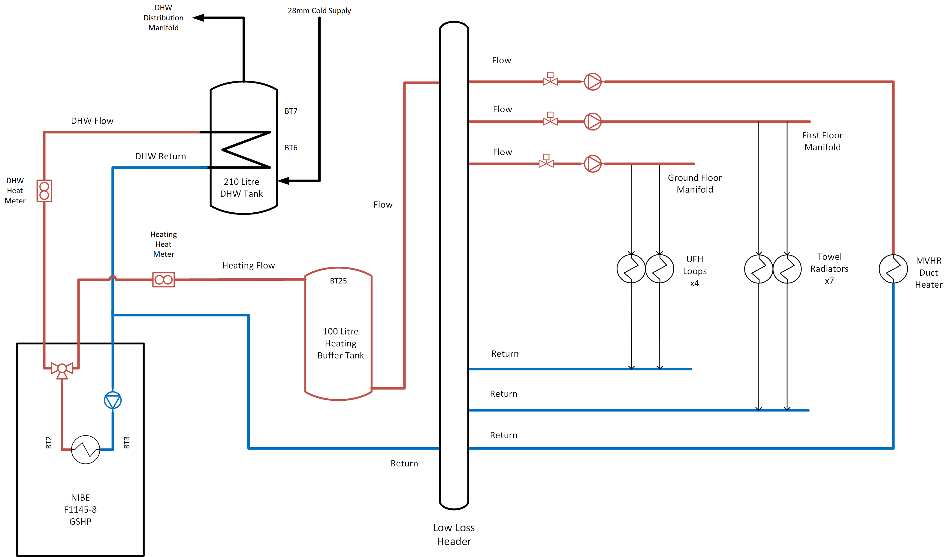
My system is unusual in being plumbed much more robustly than most seem to be:
I have a 100 litre Buffer Tank just to add Volume, to guard against short-cycling
I have a Low-Loss Header to provide Hydraulic Separation - given I have 3 pumps on different circuits for UFH, Radiators, and MVHR Duct Heater
With your set-up, when the Compressor (and Charge Pump) are Off, your other pumps will be pulling ‘Return’ water up through the Buffer Tank - as well as pulling a bit through the Outdoor Unit.
I know my LLH does an excellent job of Hydraulic Separation; when the Charge Pump is Off, even with all three of the Emitter Circuit Pumps running, the Heat Meter only registers a tiny flow through the Heat Pump (but I do run the Charge Pump almost all the time, since I need to empty the Buffer Tank). Your Buffer Tank is probably rather less effective at Hydraulic Separation.
My system’s schematic for comparison (not to scale!):
Wire the sensor as per the Room Sensor section of the SMO 40 Installer Manual (with the power off, obviously)
At power-up it should start displaying the Indoor Temperature on the main display
Menu 1.9.4 lets you set a “Heating Factor” which governs how much the indoor temperature influences the S1 Target; the default factor is 2.0 but I’m currently using 4.0
You might want to temporarily connect the sensor near to the SMO 40 while you sort out the wiring route to the preferred long-term location.