thank you, I should have it installed by the weekend so will report back how its going.
I am going to get a heat meter fitted so I can look at the SCOP too but to be honest I am a bit lost what size meter I need, I will probably buy a bundle from the OEM shop. I run a 16kw ASHP so do I need to get the largest heat meter? Apologies if this is taking the thread of course a little…
thank you, all set up now so will see how it performs overnight with a -3 set back (I can only set steps due to no internal sensor). I can see it has adjusted the S1 target temperature from the time I set the setback, so it does seem to be working.
New to the forum but a well versed NIBE user. I have an F2040 12kw. 100L buffer. 175sqm slab with UFH. WC curve is 5 with -2 offset.
WC does indeed target BT25
Hot water - you’ve done the right thing scheduling it. I have mine off except for 2 hours during my off peak cheap tariff.
Heating Schedule - I also use the heating scheduling to set a temp offset of -2 over night.
Charge pump - if your wait mode minimum is too high, it will cycle water out to the ASHP and you will lose heat energy. Mine is set to 2% in wait mode.
dT - after much tinkering 7 appears to be optimal. This also matches my UFH. With dT 5, the charge pump runs on max and caused more of a mismatch in flow and thus pulled more water from the buffer rather than the floor, which then messes with the ASHP sticking to its dT
I have been tinkering for a long time with mine, but still cannot get it perfect, and I believe this is due to mixing in my 3 port buffer, so I am now planning on a re-jig to either remove completely and run direct from charge pump only, or run it as an inline volumiser.
I should probably now look at how I get my data into energy monitor.
Welcome, good to get advice from a further Nibe user. Everything so far has been excellent and I am definitely learning from Nibe users in this community.
How are you determining what is optimal? my data suggests my Nibe can hold a pretty solid 4 for dT all the time. I dont know if this is optimum though…?
my charge pump turns off when in wait mode, so the only thing running are the circulation pumps on the buffer tank and the underfloor heating. I have set these to open loop 24/7. This soon drags the BT25 buffer temperature down below the target temperature so the ashp starts up again and the charge pump runs at about 50% - I assume to maintain dT of around 4.
mine is not scheduled yet, I lose too much heat out of it when the CH is operating so I fear if I scheduled it I wouldn’t have hot water when needed. I can lose up to 2 degrees at BT6 (charging) during an hour of running the ASHP in heating mode. This is still under investigation as to why heat is being drawn out the cylinder via the return pipe when the ASHP/ circulation pumps are running (when they don’t run the temperature is maintained in the cylinder). As a result I do a lot of hot water charging which isnt helping the bills in the cold weather!
For me personally - because it matches the dT of my floor, but I was also led to believe that the NIBE default for the uk with ufh selected in the climate flow setting (menu 5.1.14) was also dT7
I dont think it can turn off in wait mode. If your system is operating in auto mode, (menu 4.2)the charge pump is activated once the avg outdoor temp, goes above the set temperature in menu 4.9.2. and wont be deactivated until the avg outdoor temp goes back below the temp set.
In menu 5.11.1.2, the charge pump settings, you’'ll have the option to set the speed in wait mode, and “off” or “0” is not an option for me. 1% is the minimum.
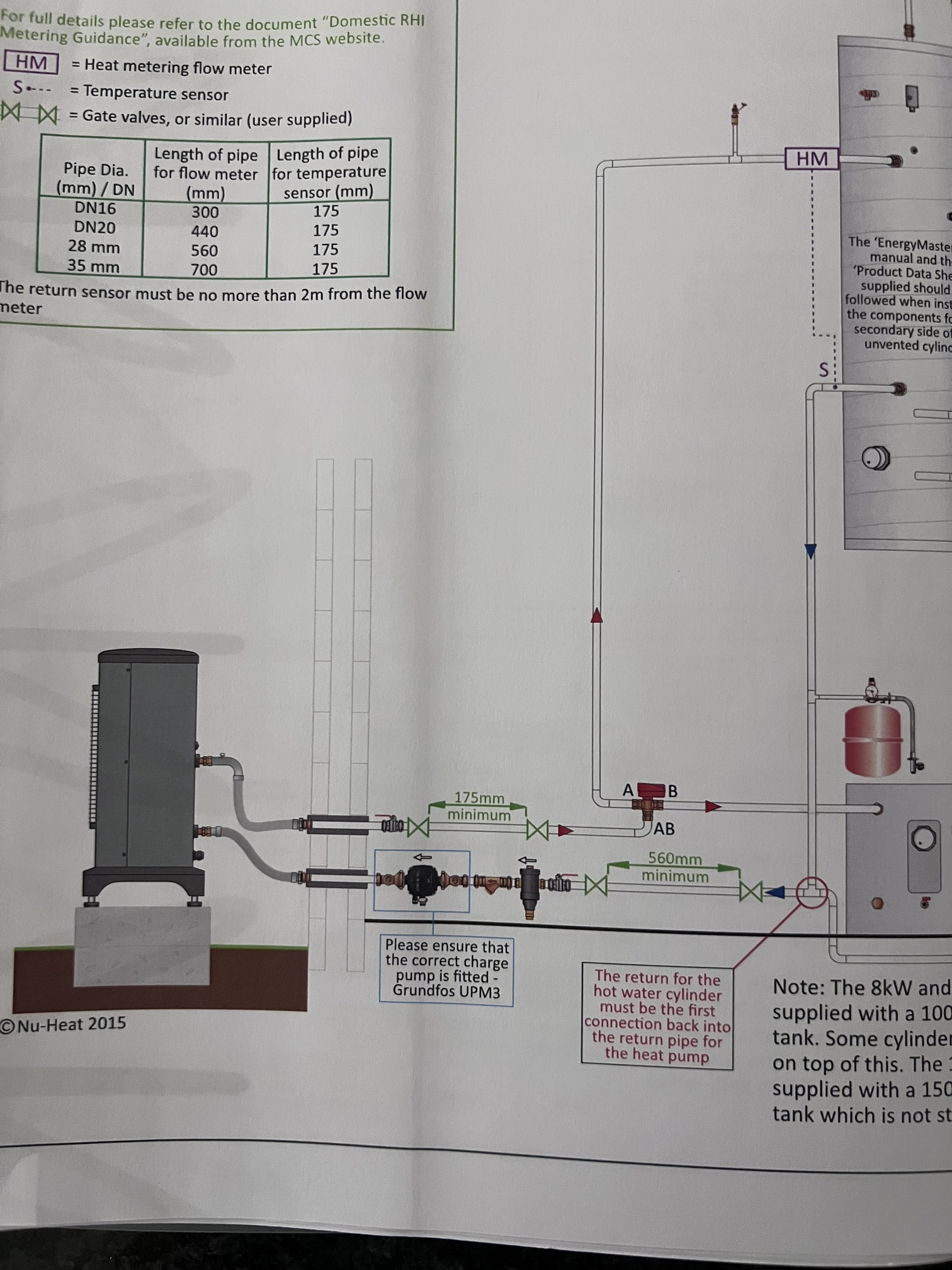
I assume you have the red shuttle valve? With tank feed in the higher tapping, return in a lower tapping? Do you have a hot water recirc circuit to the taps etc?
Is your hot water return the first on the main return pipe to the ASHP?
Good to have you on board John. From that drawing it looks like you’ve got a Nu-Heat set-up very similar to @prwv
Is the UFH your only heating emitter? If so then it’s not clear what a 3-pipe buffer is adding, like you say (apart from volume, in case the UFH pump is off, maybe?).
Sam (like me) has multiple emitter circuits with separate pumps that can (in principle) run independently, so some sort of hydraulic separation is required. My Low-Loss Header seems to work fine for that.
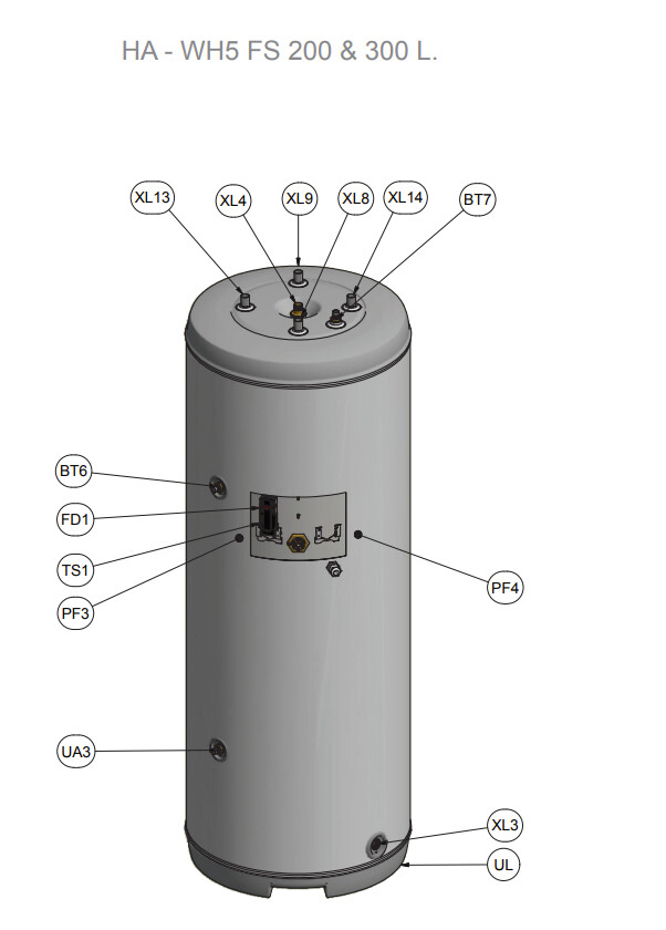
I have a Nibe titanium megacoil 300, unfortunately I dont have any design pictures / schematics so I spend a lot of time in the plant room looking at pipes to trace them. My flow and return to the ashp are on the top of the cylinder. (xl8 and xl9). The cylinder is the first connection into the return line nearest the ashp. It is this return line out the top of XL9 which is getting very warm when the charge pump and/or the circulation pumps are running. It is a lot warmer to touch than the main return line into which it connects. This happens when there hasn’t been any DHW charging so I dont believe it is residual heat in the pipe.
I don’t an option, my charge pump mode is set to intermittent, so I can only set the minimum during heating operation, which is at 50%. When the ashp is idle the charge pump is off. If I set the charge pump mode to auto, it is as per your description, the minimum I can set is 1%. @dMb and I have discussed changing my charge pump speed in idle mode, I changed it to auto and had it running in idle mode but it didn’t seem to achieve anything so I put it back to the original settings. I do not yet know which is best for me, I am chasing a few things at present.
It is indeed a Nu Heat system that was designed very poorly. There is really no need for it to be a 3 port buffer and technically I have enough minimum volume in the system already as I run it completely open zone off the WC.
They also designed if for a flow temp of 45 degrees at -3. I’m currently at 33 degrees -3. Heatloss by my calcs is also nowhere near 11kw at -3, it’s about 8.5kw tops.
The UFH pump is on constantly, but it’s not really needed, so could be done away with.
I can set whatever minimum I like in auto but I have left it as 1%, because during a cycle it’s never below 60%, and as soon as the compressor goes off, it switches to idle mode. In your scenario, I would guess with intermittent it switches off when the compressor turns off?
Have you checked your shuttle valve is wired correctly / isnt faulty?
My return connection is always cooler as it’s at the bottom of the tank. Yours are both at the top - have you checked the temperature on both the supply and the return pipe to / from the tank to see if they are same temp. My supply pipe to the tank is up top, and is always very hot regardless of a water cycle or not.
I am only losing about 4 degrees in 12 hours.
Just a thought - I wonder if you could test that by watching the bt25 reading during a hot water cycle, as if the shuttle valve was faulty you get water leaching the opposite way?
yes it switches off 20 seconds after the compressor stops.
yes, it is plumbed wrong but the wiring is inverted in the SMO40 controller to make it work…generally a bad installation throughout. The logic of the shuttle valve seems correct (45-50 degree water to the cylinder when DHW charging), however I dont yet know if its faulty in any way and contributing to my problems
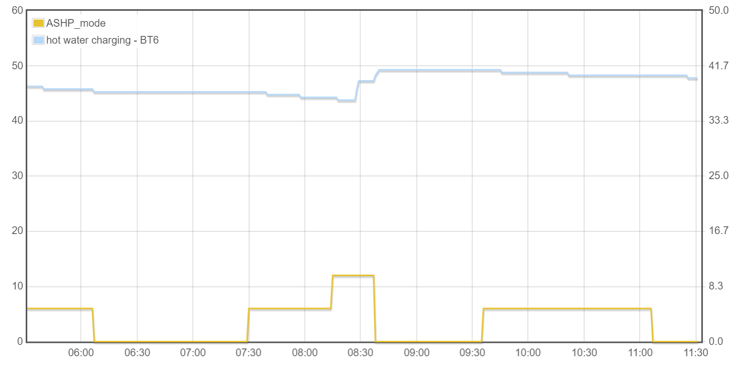
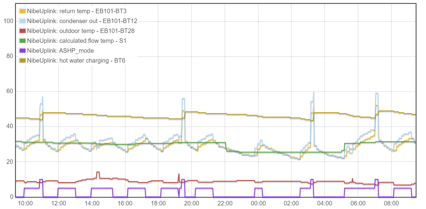
my BT25 is connected into the top of my buffer tank, when the ASHP is charging hot water the circulation pumps are still running water around the emitters and BT25 steadily drops. I have observed some hot water charging without the circulation pumps running and BT25 remains steady so I don’t think I have water leaching the other way from the heating. I am in the process of fitting some temperature sensors around the various legs of the pipes, I can then plot this onto my nibe uplink graphs and hopefully it will shed some light on what is going on. The below graph clearly shows my problem.
When the ASHP is idle (shown by the yellow line at 0) the BT6 charging temperature remains the same (flat blue line), when the heat pump is in heating mode (shown by the value 5 on the yellow line) the BT6 temperature starts to drop. After a few heating cycles the SMO controller decides the water needs charging as seen at around 0830 (shown by the yellow line with a value of 10). There has been no use of hot water so its definitely the action of the heat pump and/or circulation pumps dragging heat out somehow. If I don’t run the heat pump or the circulation pumps I lose about 2 degrees in 12 hours which seems normal heat loss out the cylinder. I have had a couple of heat pump installers visit and so far a solution has not been identified.
My common AB is definitely the right way and is the flow from the ashp.
I’ve narrowed it down to the operation of the charge pump causing the problem. The ashp was off for an hour so the charge pump was off, the return pipe out the cylinder was cold to touch. I then forced the charge pump to run (set the operation mode to auto and 1% speed in idle) and the return pipe immediately got hot as hot water was pulled out the cylinder. the flow pipe temperature into the cylinder (a non scientific touch test) doesn’t seem to change which may indicate it’s not leaking past a faulty shuttle valve.
I’ll post some photos of the actual plumbing tomorrow to see if anyone can see something obvious!
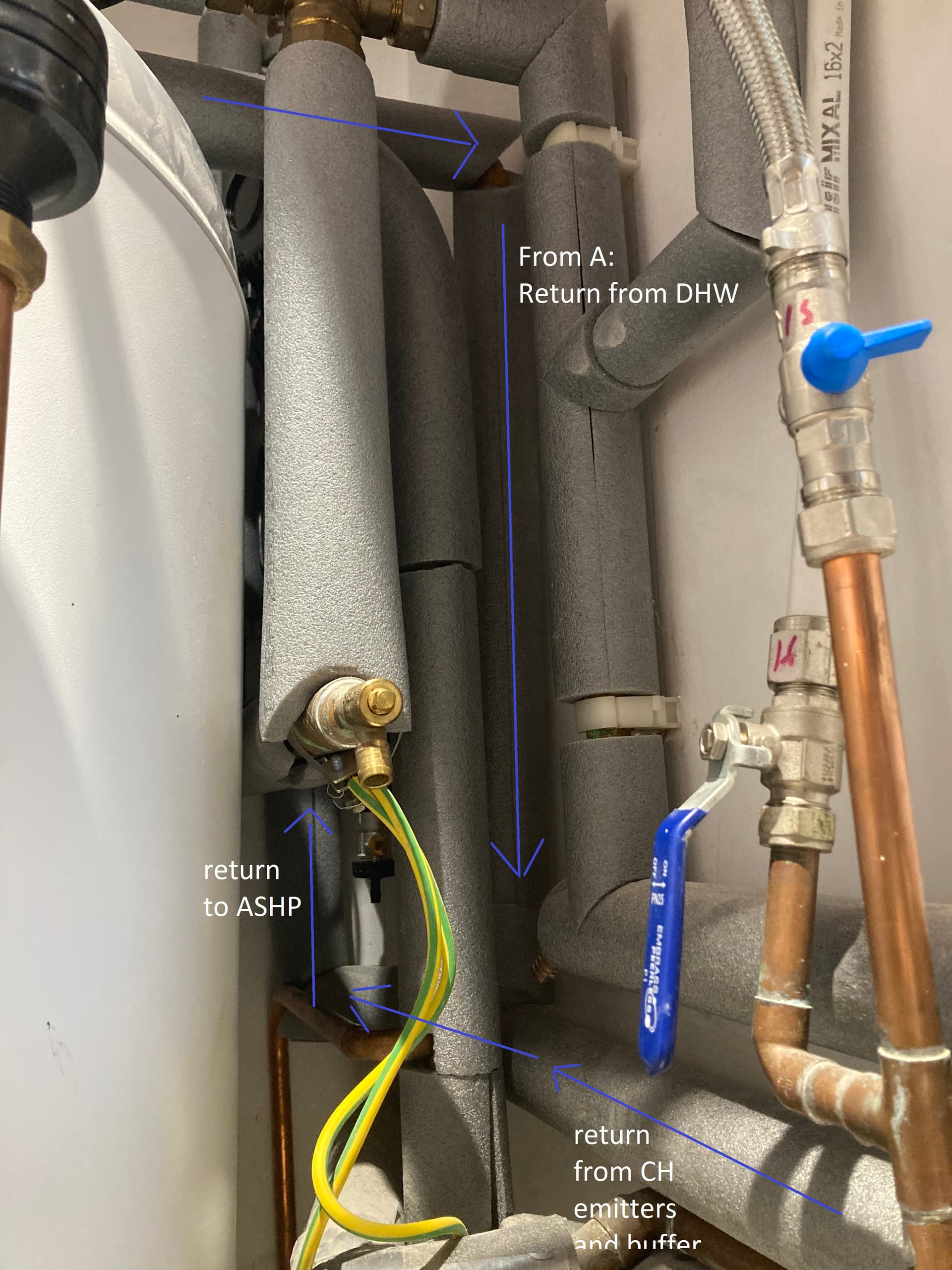
I am really not sure if these photos will help spot the cause of my problems with DHW temperature loss when the ASHP is running a heating cycle. It is a tight plant room with a lot of pipes.
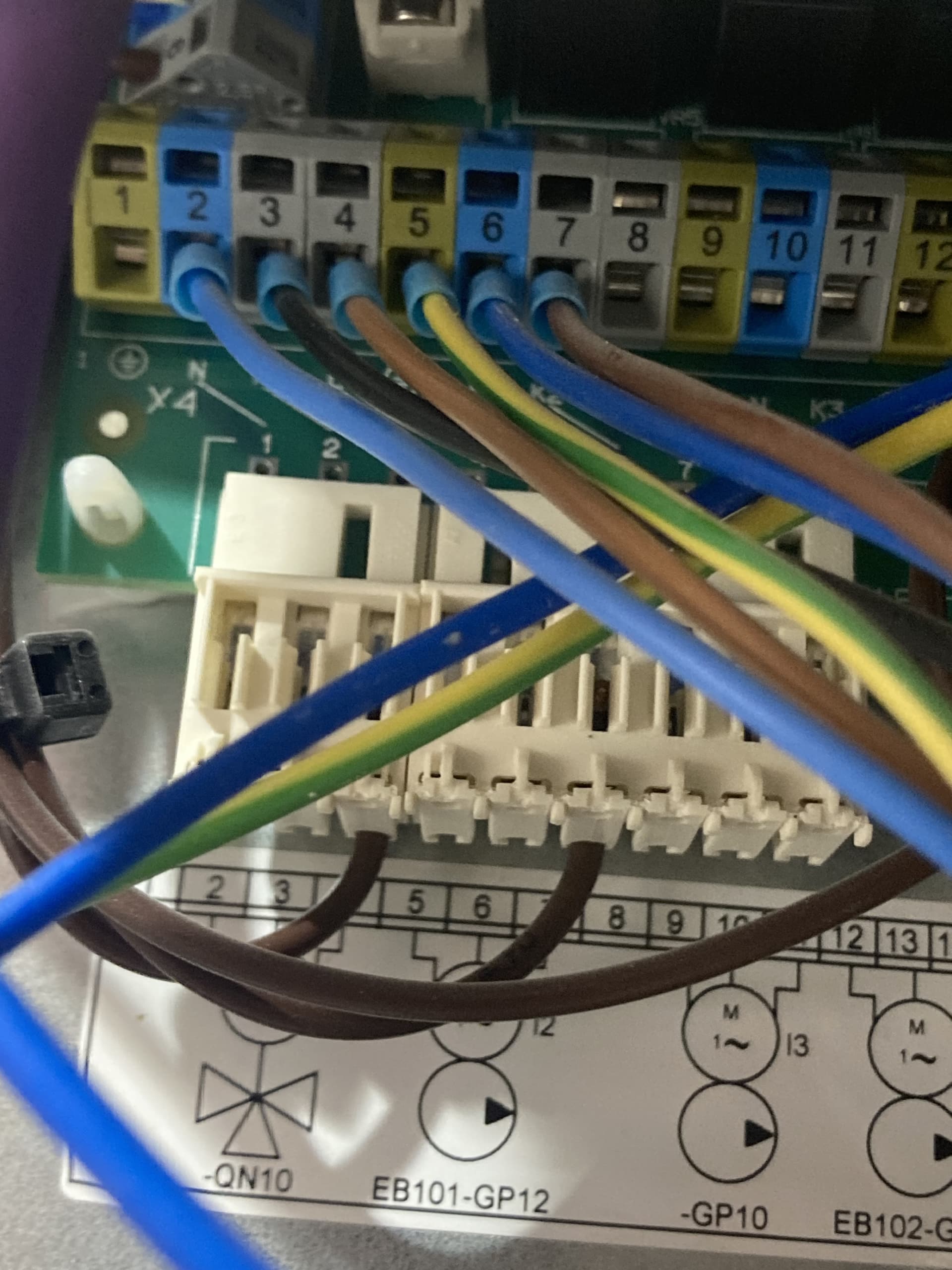
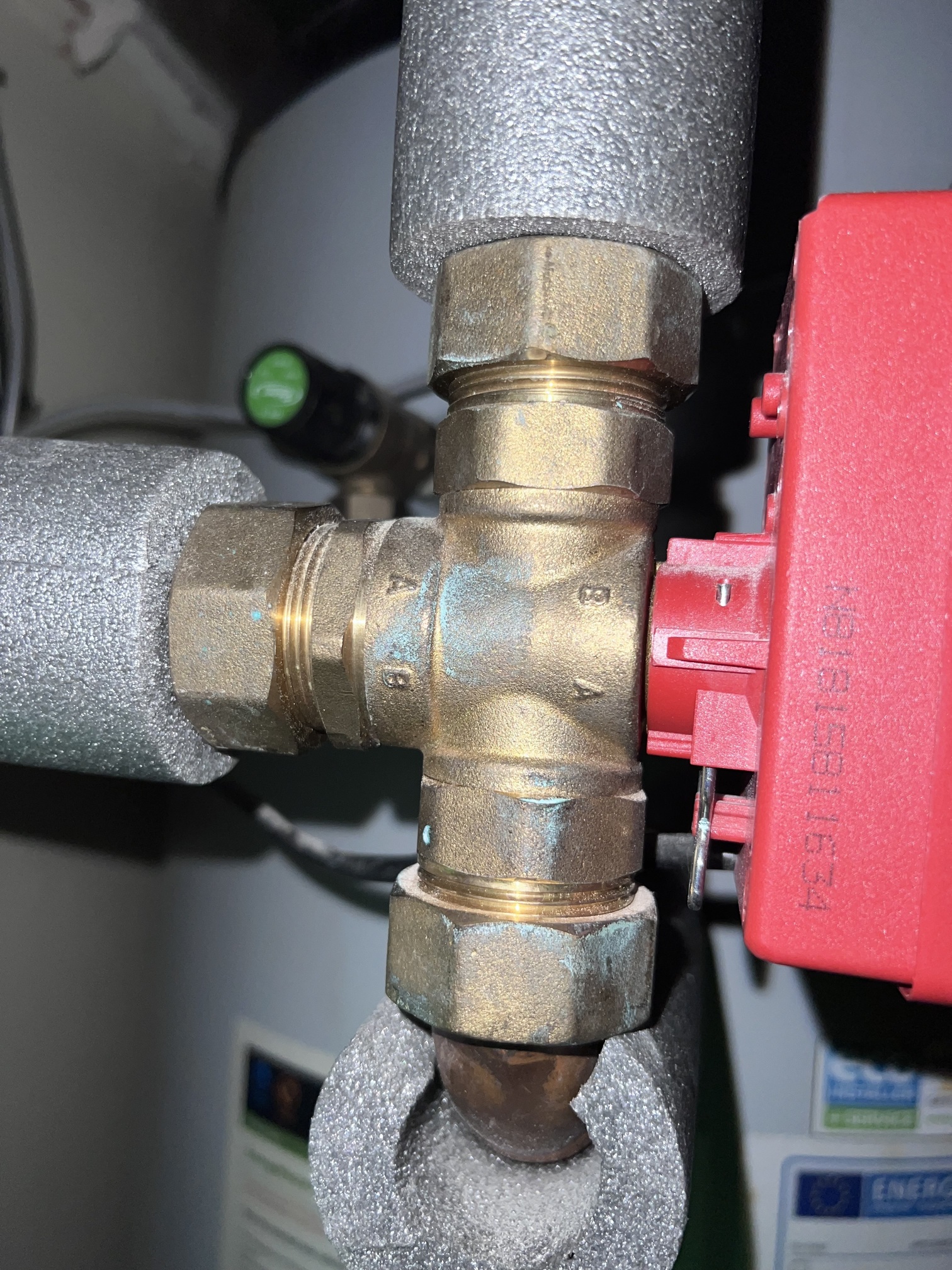
The top photo shows the ASHP flow comes down from the ceiling, round a “U” bend in the pipe work (hidden behind the tank in the photo) to the shuttle valve where it splits off to DHW or CH. The return from the DHW cylinder comes out the top, drops down behind the shuttle valve and connects into a return pipe (shown better on the bottom photo). It is this horizontal return pipe with the auto air bleed valve which is getting very warm with water pulled up out the cylinder coil when the charge pump is running
The bottom photo shows the return pipe coming down from the cylinder, connecting into a T piece on the common return pipe from the buffer tank / radiator / UFH returns before heading back upwards through the charge pump to the ASHP.
Do I have some kind of syphon effect going on? The only solution I can think of is to fit some kind of motorized zone valve or ball valve on the horizontal return out the top of the cylinder which is only open when the shuttle valve is in the DHW position. This would allow water to flow through the DHW charging coil when charging water but prevent any flow through when the charge pump is running with the ASHP in idle mode or CH mode.
I am really not sure if these photos are clear or helpful!
Also below is another graph (my logging is becoming more reliable so getting better representations of what is going on). This is around 24 hours, all is looking well apart from the saw tooth hot water charging (BT6) trace.
You do have quite a lot of Vertical pipe runs which would encourage thermal syphon effects…
If you’re happy the 3-port Diverter valve is good (and you’ve explained why you think it is) then I reckon the best way to be sure there’s no flow through the DHW coil - except when there’s meant to be - is to add a 2-port motorised valve on the return side of the DHW coil, wired in parallel with the ‘DHW’ position on the 3-port valve.
I have changed my mind…I ran another test tonight with the following results (sorry another long post - I hope all useful debug and diagnostic information for someone in the future!)
allowed a hot water cycle to finish and the ASHP turned off as there was no CH demand (positive degree minutes). With the charge pump mode in intermittent nothing was running.
The flow pipe into the cylinder was very hot and remained hot as you expect following the DHW cycle
Switched the charge pump to automatic and ran the minimum speed as 10% with the ASHP in idle mode
The flow pipe into the cylinder very rapidly cooled down (around 10 seconds) and water was obviously being drawn the wrong way (by the charge pump) through the shuttle valve and through the cylinder backwards
I think this explains why the return out the cylinder is getting hot and I am losing heat in the cylinder, I am pulling cooler weather compensated CH water up through the cylinder which in turn cools the cylinder.
I now need to determine if my shuttle valve is faulty or set up wrong.
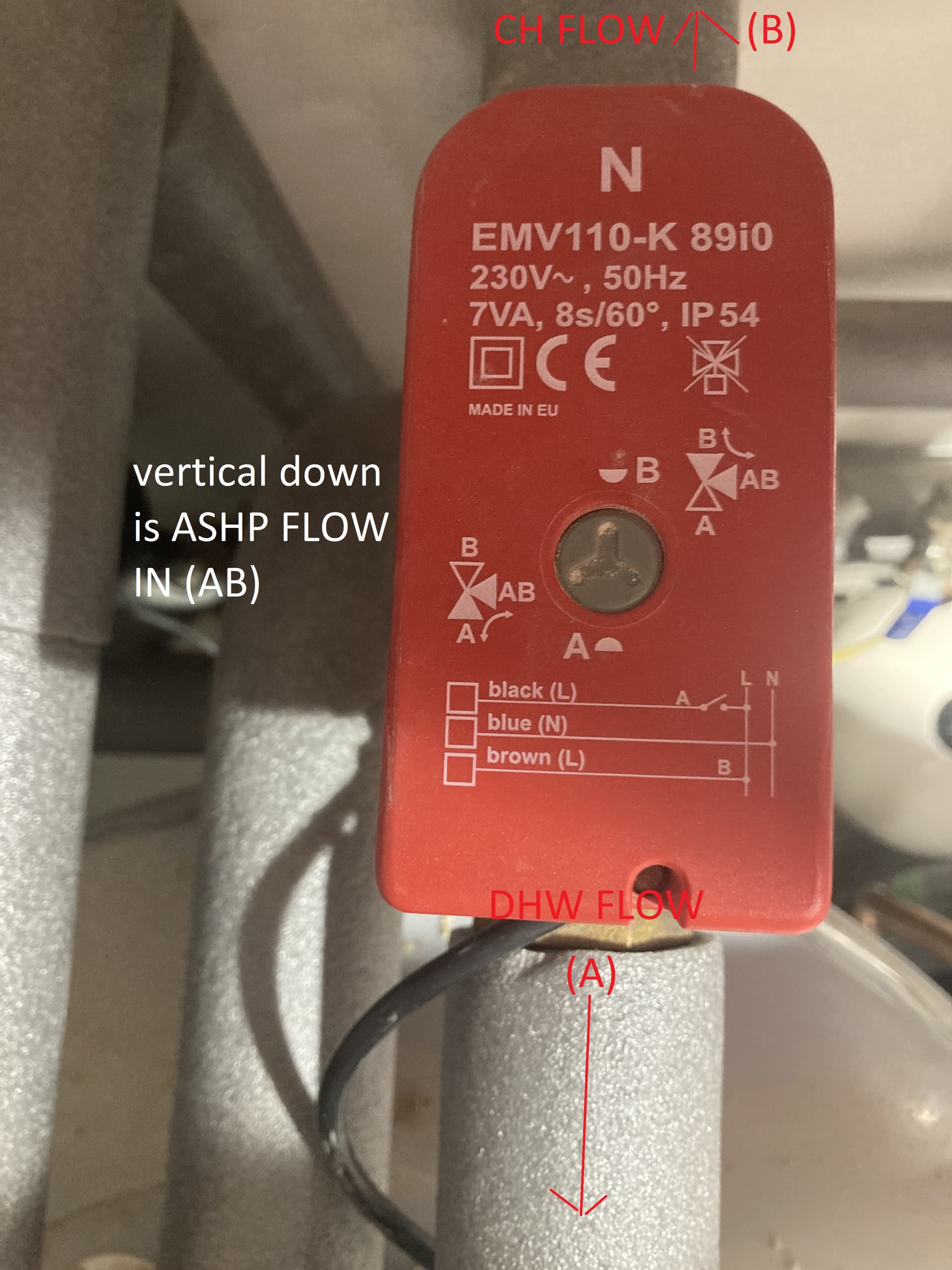
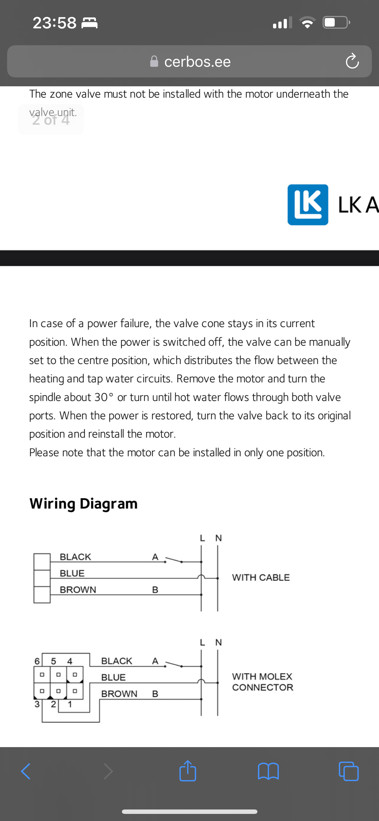
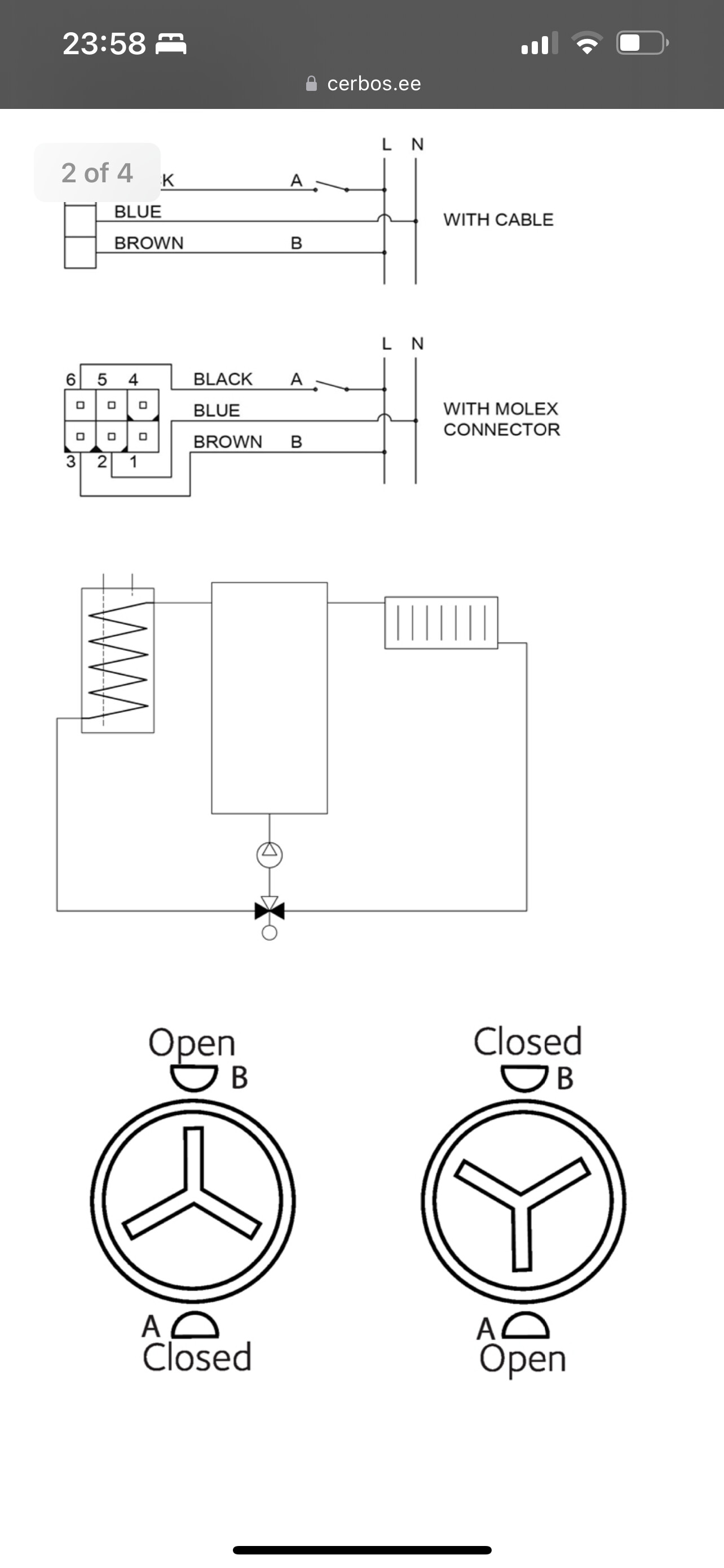
I can see that the head indicates that flow direction B (which I assume is the default position) should go to the CH but the actual brass valve underneath has this as direction A to the CH (and vice versa for the DHW). I cannot determine if the wiring is inverted to match as I dont quite understand the wiring diagrams and how the SMO40 works for switching this valve.
UPDATE 1: With the heat pump in idle mode pin 4 is live which is the brown wire, according to the shuttle valve head this puts the valve in position B. Looking at the plumbing position B is to the hot water tank. I think this means if the charge pump was running this would allow water through the cylinder.
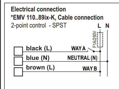
My reading of the manual (and the diagram on the top of the valve) is that:
The Blue wire is Neutral
The Brown wire is ‘permanent’ Live
The Black wire is ‘switched’ Live - and when that goes Live the valve moves to position A; otherwise it’s in position B
So I reckon you can’t infer much from checking only Pin 4; you need to also know if Pin 3 is Live or not. If Pin 3 is not Live then I agree the valve should be in (default) position B.
The puzzle is that your DHW tank is clearly heating up OK, which implies the DHW coil is seeing ‘hot’ Flow from the ASHP when it thinks it’s doing a DHW cycle - and BT25 is seeing ‘warm’ Flow from the ASHP when it thinks it’s doing a CH cycle.
It might help to check what position the grey circular indicator on the top of the valve shows for:
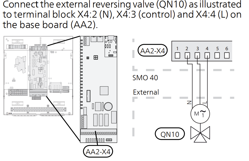
I can confirm my shuttle valve is wired as per yours:
Blue pin2
Black pin 3
Brown pin 4
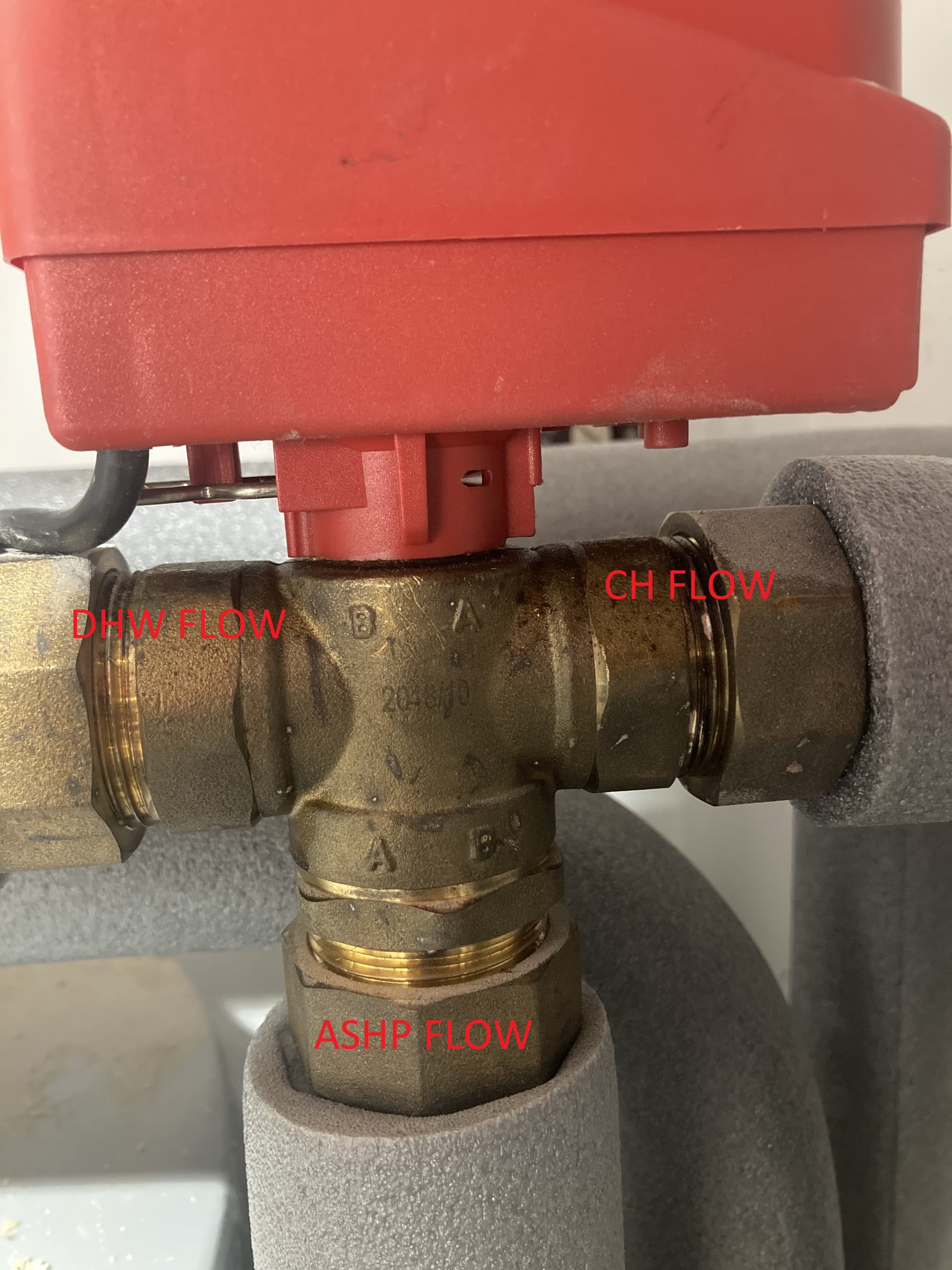
However from your pic the shuttle valve body is the wrong way around in conjunction with the brass body labels.and the pipe connections are on the wrong sides.
Your pic of the red casing shows A towards DHW and B towards heating
Your pic of the brass connector shows DHW on B and heating on A.
The thing I don’t understand is how you are getting heating and hot water still, given the above.
The way I see it: your shuttle is sending hot flow to the tank as required, but, is also allowing warm flow through the central heating and tank at the same time.
Could the mis matched orientation be allowing that?
Just looked online and the shuttle can allow dual flow the valve is at 30 degrees and not 60. I wonder if this is what has occurred with yours?
so according to the plumbing and indicators on the brass fitting this shouldn’t work, but it does (kind of)
At present I think I know that:
When doing DHW the head is at position A but the brass body has position A plumbed to the CH flow. touching the pipes confirms the water is only flowing to the DHW via position B on the fitting and not to the CH.
When idle or CH the head is at position B but the fitting has position B plumbed to the DHW. My current theory is that I’m actually getting CH flow through both A and B but I can’t see how or why.
I’ll get the motor off the brass body and see if I can determine what the actual valve position inside the brass fitting is doing.
I haven’t figured this out yet, but is there an easy way to force CH or DHW rather than waiting for a naturally occurring cycle? I’ve seen the service menu has some forced start options and one of those seems to allow me to just fire the shuttle valve - so maybe this is all I need to move the valve and then take the motor off to take a look.
Yer, forced start should allow you to put a particular mode on.
So you confirmed that during DHW that hot water was going via B. DHW and pipe got hot, and CH pipe did not.
Did you do the same during CH and see if both CH and DHW flows were equal temp?
Once you pop it off the brass, you can manually move the valve and then assure yourself where it should be for a particular position, eg B and then refit the valve body with that in position B.
I don’t know what the internal gubbins are inside, but I wonder if the mismatched orientation could be the issue?