Hi I am not a great authority on the Nibe unit, but First of all take the heat pump out of this issue for now and look at your system schematics.
Is the 3 port valve just a normal mid position valve or an open and shut to one.
So you should have hot water priority the heat pump will only charge the cylinder to whatever you have set the thermostat too and no water should be going to the buffer. When the cylinder is satisfied the valve the heat pump should go off.
If you then have a demand from your heating the 3port will switch to to open the circuit from the heatpump to the buffer to charge that and which ever zone stats you have selected they will open and your pumps will run to heat each circuit .
Your buffer is there to create hydraulic separation and smooth out the different flow rate demand from your ufh and radiators.
Now the problems you face are your weather compensation curve is only heating your buffer and you will have a flow rate set to give you a delta t of 5-8 degrees.
You now have to set your underfloor to do the same and the your radiators.
You do not want any of your heating circuits robbing each other or you will end up with constant cycling.
So if your underfloor only requires a low flow rate and your pump speed is too high your delta t could end up being 1 degree flowing from and returning to the buffer which will result in short cycling. If the you put your rads on which will have a greater demand and require a faster flow rate that will result in robbing your ufh circuit and creating a greater delta t at the buffer.
Your buffer should have flow and return sensors to monitor your temps, your circuits don’t care what temp is running through as they will only turn off when satisfied the important thing is the buffer control.
If you don’t have good stratification in the buffer the flow and return water mixes and the heat pump becomes inefficient.
Thank you. It all makes good sense. I’m on a seemingly more fundamental problem though, the flow and return are likely swapped over so flow out the heatpump connects to the returns in the house. It might explain the strange observations in measured flow and return temperature. I’m getting that double checked and then corrected if needed. Following any necessary remedial works I can then see what’s going on with the heating circuit side
If that is indeed the case, that would explain most - if not all - of the anomalies in your graphs. The Charge Pump is meant to be on the Return side, sending water back to the Outdoor Unit. If that’s connected to the Flow side instead, the water will be going the wrong way through the Heat Exchanger in the Outdoor Unit and thoroughly confusing the Weather Compensation and Charge Pump Speed Control algorithms.
Once that’s corrected (if it’s confirmed), the heat pump operation will be vastly more predictable.
As others have said, you may still face some challenges with optimising the flow through the UFH and Radiator circuits - especially if the pumps for those are switching on and off in response to a ‘call for heat’ - but we can help you with that later.
It was confirmed that the flow and return were indeed plumbed the wrong way around, it has been like that since installation in 2019 it would seem. It is early days with a new set of monitoring but so far flow temperature are now higher than return as measured at the ASHP sensors…and no charge pump operation at 1% as yet. I will post a new graph tomorrow and update my original post as I progress my journey to optimising this installation. Thank you to all for the advice so far.
Thanks for the update Sam. It’s great to hear you got that confirmed and sorted so quickly.
It’s a surprise that something so basic could have been wrong for so long (and not picked up as part of the initial commissioning) but I guess that also shows the value of your monitoring.
Between myself and Dom we have a good idea of what ‘normal’ looks like for a NIBE system so when you’re able to post some updated graphs we’d be happy to give you feedback on those.
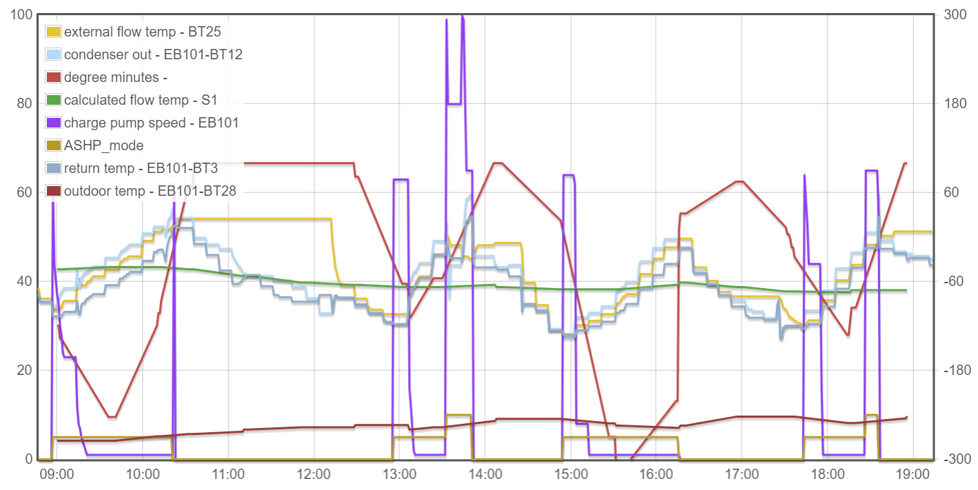
here is a day of running today, there still seems to be some strange behaviour that doesn’t look ‘normal’ based on everything I have read and seen of your NIBE systems.
The flow and return temperatures are now showing a delta T in the right direction (after swapping the hoses on the back of the ASHP). The WC algorithm generally seems to be as I would expect from how I understand the nibe unit to work. The following seems wrong to me so I welcome thoughts, maybe I am misunderstanding:
When the degree minutes drop negative the ASHP runs and the charge pump operates at a high percentage but will then drop to 1% and run like this for however long it takes to get the degree minutes back to a positive value, this can take some time and the ASHP seems to ramp up the flow temperature to way above the target temperature (S1) whilst doing so. The “zones” may have stopped “calling for heat” by this point but the ASHP still runs until the WC is satisfied. This seems unnecessary heating effort for the ASHP to ramp up the temperture especially as the WC wants a much lower temperature
Once the degree minutes are positive the buffer will hold the temperature steady (BT25) until either the underfloor or the rad circuit does a call for heat, the heat in the buffer is then harvested by those circuits and the whole process repeats. During that early heating the radiators are very hot due to the high temperature stored in the buffer. Examples of this are at 1100 and 1900. The 1900 example is strange because it seems a switch to DHW has continued to heat the buffer tank (BT25)
The ASHP is complaining about high condenser out temperatures and kicking into defrost cycles. A defrost cycle is shown at about 1330
I have very inconsistent cycling and quite long cycles at 1% charge pump.
I am wondering if I should set both the UFH heat pump and the rad pump to run 24/7 and open up the zone valves and see how the system behaves, but I am not 100% clear if it is the zoning causing this behaviour or something else.
(ignore the very variable outdoor temperature. The NIBE outdoor sensor was relocated to move it away from a heat source as it was measuring 5 degrees too hot all the time, it now seems to be in direct line of the ASHP fans and hence is showing a lot of variance - I will move it again)
Thanks Sam; that’s definitely looking better but like you say, not quite ‘normal’ yet.
That’s a good idea - at the very least to eliminate it as a variable. In general, the best approach is to ‘get the heat out’ - keep the water circulating through the emitters and let the WC decide on the temperature of that water. The flat yellow line from 10:15 until 12:15 shows hot water sitting in your buffer tank; presumably there was a ‘call for heat’ at 12:15.
It’s normal for a NIBE system to dump heat into the heating circuit at the end of every DHW cycle so that’s not necessarily an issue.
Long cycles are fine but the 1% charge pump is the next thing to focus on, I reckon. High temperature errors are often related to a lack of flow so probably related to that too. The charge pump speed is adjusted to try to deliver a specified delta-T between Flow and Return. It’s hard to see from the graphs; what sort of delta-T are you getting on the ‘stair-steps’ when in heating mode?
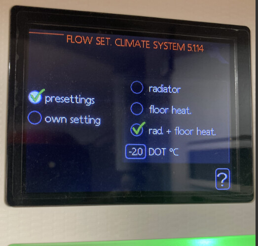
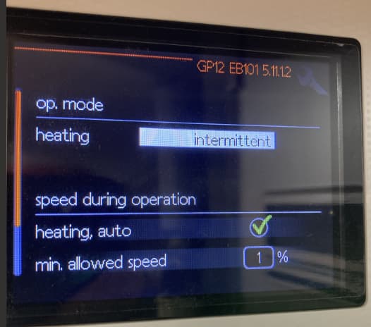
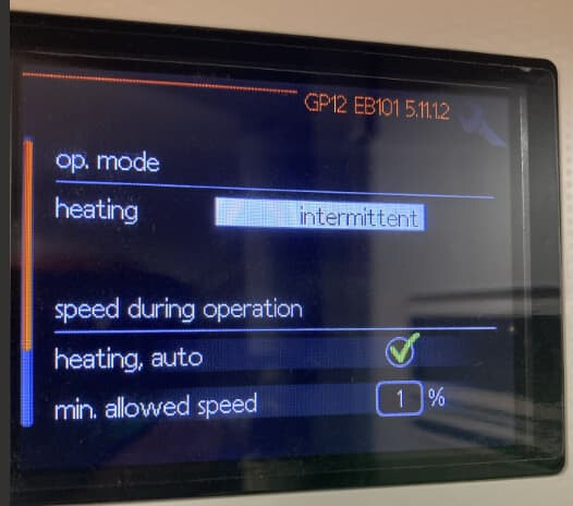
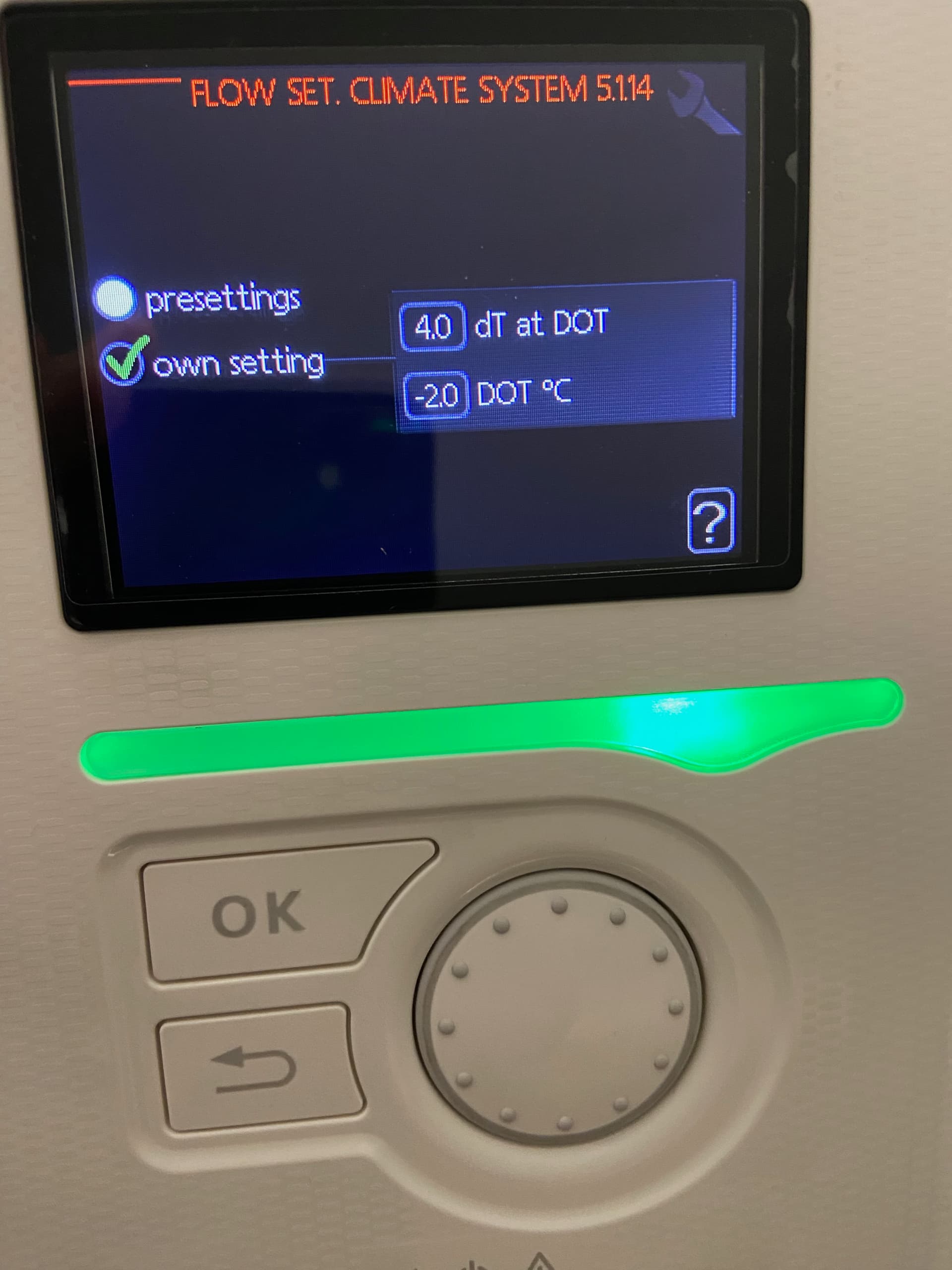
Are you familiar with the ‘Service’ menu you get by pressing and holding the ‘Back’ button on the controller? There are some settings in there which relate to the pump speed control - for example 5.1.14 “Flow Set. Climate System”. Could you check what that is set to (and any other settings that relate to charge pump speed - as Dom wrote the other day, there’s a minimum pump speed setting in there somewhere, which I’d be inclined to set to 50% or thereabouts).
I’m not sure how easy it will be to read since the lines are split across 3 graphs, with a lot of empty space, but here’s what ‘normal’ looks like for my system:
The narrow higher-temperature peak is a DHW cycle. Note I have the Degree Minutes value for Compressor Start set extra-negative at -500 to reduce the number of cycles. I wouldn’t advise trying to match that.
Also, I have 5.1.14 set to a delta-T of 4.0 (at -2C) which is a smaller delta-T than the default, hence my Charge Pump runs at 100% to try to achieve that lower value.
The pumps on my emitter circuits run 24x7 so there’s always a ‘call for heat’.
It seems to depend which emitters are in circuit. If just the UFH then its around 3 deg dT and with the radiators in circuit it is between 4-7deg dT. From the logging I don’t know how many emitters are in circuit at any one time because I do not log the “call for heat” from the thermostats. This will become easier to see when I put all emitters in circuit and run the UFH heating pump and radiator pump 24/7.
As per David’s advice I would definitely try upping the min. allowed speed.
I personally have ours set to 25% but you could try higher, like 50% as suggested by David and then dial it back if that is too much.
The DOT could be increased to say 4C.
thank you, sorry I am not sure if I was correct or not above? Is the DOT the delta t or the dimensioned outdoor temperature showing -2? to change the delta T only seems possible with the “own setting” option and then I can set 4 degrees at -2. I have no information about what this should be from design or anything so am a bit blind when changing this.
I’d have no hesitation in changing those two “1%” min. speed settings to be much higher. My charge pump isn’t allowed to go below 20% even when the compressor is off.
I’m with Dom; set it to 50% min. speed for now and see if that reduces the incidence of high temperature alerts.
Thank you. I have made those two changes as recommended. I will report back with a new graph following further monitoring but initial indications look positive
today I ran with a delta T of 4 degrees at -2 and a minimum charge pump speed @ 50%. I also removed all zoning and let the UFH and radiator pumps run all day.
My general observations from a comfort perspective is that the house got too hot by the end of the day.
My observations from the data is that the heat pump ended up running all day with the exception of 2 small periods, but as soon as the heat pump turns off the circulating water loses heat and the WC kicks the heat pump back in. Would dropping the flow temperature help with this?
The heat pump defrosted 3 times but it hasnt raised any high temperature alarms when running in this configuration today.
I do not yet have any form of electricity usage being monitored so I will have to wait until tomorrow when the Octopus app gives me a whole house usage and compare that to previous days.
It’s looking better, isn’t it, and an absence of alarms is always good
I was half-expecting the Charge Pump speed to be bumping along on the minimum 50% setting you’d specified but it’s significantly higher a lot of the time, which is excellent; maybe that’s the lower delta T helping.
I’d be inclined to set a minimum Charge Pump speed of say 10% when the compressor is off; it looks a bit odd when it falls off a cliff when the compressor stops, and there must be some heat in the compressor which wants to come out.
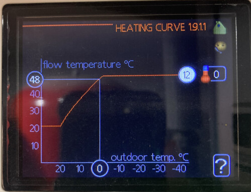
If the house is getting too hot that implies you’re on too high a WC curve, and I’ve been thinking an S1 target over 40C is really very high (though it depends on your heat loss). Which curve are you? I’d recommend dropping that down one or two (which will lower the flow temperature for a given outdoor temperature),
Do you have the optional internal temperature sensor (BT50 in NIBE Uplink) and do you get much passive solar gain?
I have the “problem” that my house went from 21C to 22C between 12:00 and 14:00 today despite having no heating since 09:30, due to some south-facing patio doors on the ground floor. Without BT50 the WC algorithm can only work off the outdoor temperature so it can’t adapt to how hot or cold the house actually is.
I have significant solar gain upstairs on the new extension, this has a lot of glazing in all directions and is very well insulated via the SIP construction - this is where the UFH heating is.
Downstairs in the bedrooms (the house is upside down) there is minimal solar gain and this is the original 1960s bungalow which isnt that well insulated. The emitters are radiators which do look large so I assume have been sized and fitted to support the ASHP installation.
I dont have the indoor sensor fitted (many problems with my installation not just flow and return mixed up) so it isnt showing on the uplink and the WC isnt using it. A local installer has promised to post me a spare one so I aim to fit that as soon as possible. I just have to choose the best location, upstairs to assist in understanding such things as solar gain or downstairs so the WC can understand the heatloss a bit better in the part of the house that isnt as well insulated.
I have not seen how to do this in the settings, it only seems I can set a minimum for heating or for DHW production. Is this in a different part of the service menu?
I dont think my heat loss is overly high, when the ASHP is off the indoor temperature holds steady fairly well and will slowly drop over hours. I have also thought the target is too high but have been waiting to understand more before adjusting. I am running on what I think is curve 12 as per the below. I shall drop it down a couple and rerun a day with all other variables the same.
I spoke too soon, I had one at the end of a 45 minute DHW water cycle an hour. The ASHP reported a high condenser out temperature and the logging shows BT12 got to 59.7
Thank you for all the ongoing help and advice, I really appreciate it and this community is such a great resource.