If my math is right, and it puts out 0.080A at 200A input, and I don’t change the burden resistor on my emonPi pcb, the voltage will be 0.08 * 22 ohm = 1.76v. Is that too high for the emonPi? I’ve read that the input is normally 1.1v with the SCT-013-000 CT so should I change the burden resistor to >13.75 ohms (I can put a 39 ohm resistor in parallel with the 22 to get ~14 ohms, for ~1.125v? I could put a 36 ohm resistor in parallel to get 1.096v.
The datasheet from YHDC doesn’t show a diode to short the outputs on this CT, whereas the sct-013 does have one… http://www.yhdc.com/en/product/900/
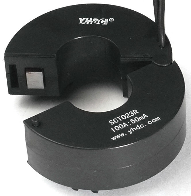
For reference, the reason I’m looking into this CT is because I have 4/0 gauge wires on my 200A panel (I’m in the US). and I’d like to measure whole-house. This CT has a 23mm (0.9") opening.
Hi Bill,
Yes, I’ve read that, and every post I can find in this forum (and others), but those CT’s are $40+. I was hoping to use something cheaper
I’m not afraid of any hardware modifications that I might need to do, but when it comes to software, I’m not as good. I can make changes to code as necessary but I’m never sure that if I do a software update, my changes will get blown away or not.
Seth
Even though you have 200 Amp service, you’re limited to quite a bit less than 200 Amps by the transformer that your house is connected to, as well as the number of other houses that may also be connected to that transformer. Three or four houses sharing a 15 kVA or 25 kVA transformer is common practice.
Add to that the fact you don’t normally run everything in your house at the same time, and the number you end up with is significantly less than 200.
That’s great, thanks! But I was under the impression (and I must be wrong) that I needed a 200A CT for each leg of my 200A panel…? I was having a hard time finding a cheap one with a large enough diameter to fit 4/0 wire because I was looking for a 200A CT
If you were to use a 200 Amp CT, you’d be using only a small portion of the CT’s total range. As a result the resolution would suffer. Operating at the bottom of the CT’s range results in measurement innacuracy, especially with reactive i.e. non-resistive, loads.
To maximise measurement resolution, the voltage across the burden resistor at peak-current should be equal to one-half of the ADC’s analog reference voltage.
If you use a 200 Amp CT, you’ll likely be using only the bottom 25% of the CT’s range.
50 Amps at 240 Volts = 12000 Watts. You’ll find your typical load is much less than that.
To put it another way, add up the numbers on all the circuit breakers in your load center. You’ll probably find they total more than 200. How could that be, you ask. It works because you don’t operate everything on every circuit in your house at the same time.
We have a name for that: Diversity. In the UK, there are rules for how much allowance can be made. E.g. It is assumed that the actual demand will be:
Lighting: 66% total demand
Heating and power: 100% up to 10 A + 50% balance
Cookers: 10 A + 30% balance + 5 A for socket
Water heaters etc: 100%
But in all cases, if you know that there is a particular load, you must use the actual value for that and apply the rules to everything else.
I was also curious about the A/D that the raspi uses; everyone talks about the 1.1v (max?); I thought that the raspi had 3.3v tolerant inputs, so we should be able to map as much of the maximum current to 3.3v instead of 1.1v…? Or are we talking about the Atmega328, which even has 5v tolerant inputs. The 1.1v sounds like the 328’s internal 1.1v analog reference; is that where all this comes from?
Sorry for all the questions; this forum is excellent, though!
Seth
It boils down to the building occupant having enough sense (and we both know there’s a shortage of that)
to not run their aircon and electric heat at the same time.
If they decide they want to run their clothes dryer, space heater, stove, and oven as well as the usual loads e.g. lights computer TV, etc, then say the water heater stat closes, (this example is of an all-electric house) they’re probably going to trip the main breaker, or pop the pole mounted fuse on the transformer high side.
According to the data sheet I’m looking at - the genuine YHDC one linked in the top post - no it doesn’t. I would not trust the Fleabay data sheet - even the photo there clearly shows 50 mA, and historically others who have factored YHDC CTs have published incorrect data, so there is precedent.
The YHDC data clearly says it is 200 A : 50 mA, the same as most of the YHDC CTs, so it will work straight away into the emonPi with no hardware modification. (And if you’re considering the 100 A version, that too has a 50 mA secondary.)
However, if you’re considering operating either up to the maximum current (expect linearity to suffer if you do), then you do need to add a parallel burden resistor to lower the effective burden resistance.
Unless you’re using the 100 A version to 100 A max only, emonhub.conf will need a minor edit to the “scales = …” line to give the correct scale factor.
As the top post pointed out, no protective device is shown, so it would be advisable to fit a TVS or a pair of zener diodes on or in the plug so that the CT is not open-circuited if the plug is pulled out of the emonPi.
Talk about inconsistencies of Chinese FleaBay listings…
The listing says 200 Amp input, 80 mA output. The picture shows a 100 Amp:50 mA unit.
I don’t think I’d trust 'em any farther than I could throw 'em!
Yeah, I noticed the discrepancies as well…I blame the chines-english conversion. The actual YHDC website had better, more consistent specs. BUT, I just decided to follow Bill’s advice and I picked up 2 WattCore WC1-100-MA100 CTs off eBay for $50 shipped. A little more than I wanted to spend, but I’d rather get good stuff than question the cheaper stuff.
I wouldn’t be quite so fast to dismiss YHDC. I can only speak for the STC-013-000, but since I first tested one back in February, 2012 both the build quality and the performance has steadily improved, while the price has remained much the same.
rI just purchased 2 sct230r-200A to test them. If they do not work, I will get magnelab or wattcore, like Bill suggested before…and take on the required mods.
Because of the large NA wire size, I have purchased two SCT023R CTs from YHDC. They are marked “200A:50mA” After soldering on the plugs, according to the group’s guide, I don’t seem to be reading anything on my input #1. I have connected the CT to one leg of my 220-0-220 mains to test it. It seems that I should be showing something on the input. Not being an engineer, I’m not sure what is going on here and what I need to do. Does some component (resistor?) need to be added to the EmonTX.3.4? If so, what? I’ve read the configuration guide but lack the expertise to understand what I’m missing.
I have calibrated my 9v AC/AC so that Vrms reads correctly (thanks Glyn!). I have tested input #4 using an SCT-013-000 and it seems to be working correctly.
When I test the SCT-013-000 with an ohm meter I get a reading (150 ohms) but when I test the SCT023R I only get an open circuit. Is this normal?
Sorry for the elementary questions but I’m lost at this point.