That’s definitely NOT normal. I’ve not tested that particular model, but I’d expect you would read about 100 Ω - much the same as the SCT-013-000 - looking into the C.T. with nothing else connected. It sounds very much as if you have a faulty one.
They’re usually close to 100 Ω. That’s a bit higher than I’d expect, but I wouldn’t worry about it.
Ok, I have connected the good CT to power 1 but am not getting any input. I deleted the input and feed and recreated it. Also cycled the power on the emonTX3.4 and rebooted the Rpi3. Only see a “0” Other inputs and feeds are working fine.
Have I missed a step here? When I attached the CT, I felt a slight vibration so it should be getting some input.
That’s credible. It has the same number of turns as the -013-000, I’d expect them to use the same wire, but each turn is going to be quite a bit longer.
Hopefully a silly question - how did you connect the C.T? Tip and sleeve?
White to tip and black to sleve. I checked the plug on the “bad” CT and think that was faulty–wires gave 184 ohms when I connected directly. The CT I have connected now gave a good reading from the plug, however, it may be losing contact some way when plugged into the cmonTX.
Will keep pluggin on this (pun intended) until I’m sure of the connection at least.
Many thanks–I’ll post the results (or questions)
Bob
If you insert the plug with the cover off (and the emonTx not powered), you should read the internal burden resistor of 22 Ω in parallel with the secondary winding resistance, so about 19.6 Ω. Anything more - especially 184 Ω - means a bad connection.
It’s not unheard of for the plug tip and its solder tag not to be connected, and I have had similar problems with the sleeve too.
You might have to push with quite a bit of force to make sure the plug is fully home in the jack.
(Although ususally when that’s the problem, the result in emonCMS, or at the emonTx serial port, is random values vice zero)
I think I’m finally set. By replacing both plugs with two from another source, power1 and power2 seem to be reading correctly. I had to reverse the CT on power2 for some reason I don’t understand, because it was reading negative–now one CT is pointing the opposite way from the other.
Robert, the 184 ohms was reading across the CT leads. It was not connected to the emonTX or the mains.
The next phase of my project is to combine power1 and power2 to read whole house consumption. I’ll study the information Robert sent last week.
Many thanks and much appreciated for all the help today! Time for a beer… Cheers!
Bob
That’s normal. The current in each leg of a split-phase system flows in opposite directions, hence the need for the CTs to face opposite directions to yield “positive” numbers.
OEM Convention says consumption is viewed as a positive value and export (e.g. from a PV system) is viewed as a negative value.
Sounds like a plan.
Good to hear you made progress.
Re the SCT023R protection when not connected to an external load. I note that several Aliexpress sellers show a schematic with no protection, yet YHDC’s catalogue page at Dropbox - 20 R series split core CT.jpg - Simplify your life shows a TVS (but no info it its specs).
But, remember that Chinese datasheets are even less reliable than Chinese product.
They may have evovled the product to now ALWAYS include a TVS as shown in the datasheet, they may not have.
BTW, their SCT013-000 with EITHER a TVS or a burden resistor… at the customer’s choice. So if you pick these up on eBay, they could be either.
That could be slightly misleading. The 100 A version with an internal burden resistor is the SCT-013-000V
The characteristics of the TVS in the latest SCT-013-000 are in the test report in “Learn”, so you could have looked there.
I don’t know what your data sheet from dropbox says, but that’s what mine from YHDC lists. Please attach your external document to your post as opposed to putting it on a third party site. If, for some reason the image becomes inaccessible, your post loses it’s value.
I have noted various sellers of SCT023R that show a schematic with no burden and no TVS, no overvoltage protection essentially.
If a seller shows that schematic, that is what you should expect to have delivered if you buy from them.
I could not find a daasheet for that CT on yhdc.us (which appears to be their ‘official’ website.
The dropbox link was in an unsolicited email from yhds trying to sell me CTs, and the dropbox contained a datasheet that showed one schematic and it included TVS (without characterisation).
Are you chiding me for publising in a dropbox. Take your complaint to yhdc, it is probably their dropbox and the existence of the 2017 catalogue with product that is not easily found on the website might suggest the website is out of date.
Could tha Aliexpress sellers showing no TVS be correct? They may be, it could be that the product in the reference I gave has been revised but kept the same part number.
Re the SCT013-000V, yes the suffixed item appears in some datasheets and not in others that contain the general statement that the customer can choose either TVS or resistor without mention of part number codes. Some datasheets show the output as xxmA or xV and that hints whether it has an internal burden, but it would be wrong to assume that in general CTs contain effective protection agains overvoltage, in fact it is safer to assume otherwise until the configuration is proven.
If you buy a SCT023R from a seller that shows a schematic without TVS then you should expect it does not have a TVS, but since a presumably more recent datasheet promoted by yhdc just days ago shows a TVS, it may well have one. If it doesn;t, it would be wise the wire a bidirectional 9.1V TVS (eg P6KE9.1CA) or inverse series 9.1V 1W Zeners into the cable to protect the CT if it is unplugged from the monitor when primary current flows.
I’ve taken apart a bunch of these, you can pull the guts out without tools and see the little circuit board. In my experience with ten or so various models, they ALL have the TVS diodes. The voltage types (005, 020, 030, 050) all have a burden in addition to the TVS. I’ve seen some with two burden resistors in parallel to get the desired value. I admit I have never seen an SCT-013-000V. I assume its the same with a 20 ohm burden, although I can’t explain why they wouldn’t call it an SCT-013-100 in keeping with their general naming scheme.
For larger cable or higher amperage, I prefer the SCT019-000. It has TVS diodes and also is available as a voltage type (with burden resistors). It has a 200A limit and a turns ratio of 6000.
We recommend you NEVER rely on any internal protection that a c.t. might have, but always ensure that it is removed from the cable (split-core types) or that the circuit is not energised, before disconnecting.
Note that it is always safe to short-circuit a c.t. In some cases (e.g when there is an internal burden), it _might _ be safe to open-circuit it, but in general terms it is not.
Therefore, if the c.t. must be left in place and the circuit needs to be put back into service when the instrument connected is removed, you should short-circuit the c.t.
(The mechanism that creates the danger is this: Without a burden, all the primary current is magnetising current and the core will be completely saturated except for a very short period at the zero crossings. There, the rate of change of flux is so great that voltages of several kV can be generated, and (usually) the insulation flashes over, destroying the c.t. There is obvious danger if this happens and anyone is too close.)
In the real world, it is not always practical or desirable to turn a circuit off to disconnect a CT secondary circuit, and if you take Robert’s position, the ONLY acceptable practical foolproof solution for this type of CT is a CT with internal burden, and SCT013-000 should be replaced with SCT013-000V and the emontx3 firmware recalibrated for the new combined burden (and at somewhat a loss of resolution).
For me, I am happy with the SCT013-000 with TVS (I have measured mine to be sure they are fitted) and I don’t lose sleep about low reliability connectors like 3.5mm TRS resulting in damage to the CT if the connection fails.
At least one of the competitors allows CT output leads to be addiditvely ‘combined’ in a Y junction cable, which hints that they probably use internal burdens in each CT and series them up in the Y cable.
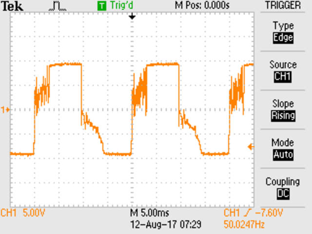
Above is output from my SCT013-000 with TVS, 25A primary current and no load. The action of the TVS is apparent.
I think you need to read what I wrote again, carefully, particularly the first paragraph.
In today’s world, it appears that everyone is responsible for everyone else’s safety except their own. Deplorable as this might be, it means therefore that warnings have to be put in place to protect those who don’t know, and worse, those that don’t want to take steps to learn, from their own ignorance.
Neither do I, because at the first hint of dirt, the voltage will automatically rise and burn it off. And the possibility that someone will be handling the connector then is low - especially if they have observed sensible precautions.
Are you confusing burdens and protection here? You can parallel true c.t’s, but you must connect internal burden types in series to add the voltage.