First steps with emonESP

So I’ve tried to set up emonESP on a Huzzah using via the Arduino IDE and not made much progress.

Whilst I am very much a novice with esp8266, I have previously set up and used an Arduino IDE with an Olimex ESP8266 and played with a generic ESP-12 some months ago but progress was slow and I moved on to other more pressing projects.

I use the Arduino IDE a lot and am familiar with most aspects of it. I have updated the IDE a few times since my original brush with ESP8266 and therefore start again with adding esp via the boards manager, so all fresh and latest builds.

I have followed the “Option 2: Using Arduino IDE” part of the EmonESP readme and had no issues beyond the ESP8266FS folder unpacking to <home_dir/Arduino/tools/ESP8266FS/ESP8266FS/tool/esp8266fs.jar instead of <home_dir/Arduino/tools/ESP8266FS/tool/esp8266fs.jardue having created the ESP8266FS dir as instructed in the prior step, but that was easily fixed once I went to use the tool and found it wasn’t on the menu.

Do have a couple of question’s though.

  1. “Install Arduino IDE 1.6.8 from the Arduino website” why? is there an issue with later builds? or should that be >1.6.8?
  2. “Select Tools > Board > Generic ESP8266 Module (required for EmonESP)” again, why? is there a difference? one would naturally assume if your exact board is listed, that might be the bast tool for the job.
  3. Having selected “Generic ESP8266” what other settings are required, because there are a few!

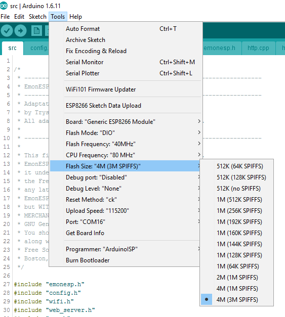
The default “512K (64K SPIFFS)” looked obviously wrong so I took a guess at “4M (3M SPIFFS)” as the Huzzah is a 4M device and the emonesp code has apparently run on a 512K device so 1M should suffice, should it be “4M (1M SPIFFS)” ? As for the other 7 settings I just went with the defaults you see.

One of my initial failed compiles was due to not having the “MQTT Lib” installed, I have now remedied that but for other “first timers” it might be useful to list the dependencies and/or how to include how to install the needed libs.

After a few false starts I was able to compile and upload to the esp8266, but have not been able to upload the data folder. Am I missing something, The file is now correctly located and the tool is listed in the menu after a IDE restart, but still no cigar!

The instructions step seems quite straight forward “Upload ‘data’ folder: Upload data folder (home.html web page etc) using tools > ESP8266 Sketch Data Upload tool.” But it doesn’t work. Even with both verbose compile and verbose upload set in the IDE’s preferences, this is all I have to go on.

`Arduino: 1.6.11 (Windows 10), Board: “Generic ESP8266 Module, 80 MHz, 40MHz, DIO, 115200, 4M (3M SPIFFS), ck, Disabled, None”

[SPIFFS] data : C:\Users\paulb\OneDrive\Documents\Arduino\EmonESP\src\data
[SPIFFS] size : 3052
[SPIFFS] page : 256
[SPIFFS] block : 8192
/config.js

/home.html

/style.css

[SPIFFS] upload : C:\Users\paulb\AppData\Local\Temp\builda6e400cad64a03f9af6b67e54a7cc6dd.spiffs/src.spiffs.bin
[SPIFFS] address: 0x100000
[SPIFFS] reset : ck
[SPIFFS] port : COM16
[SPIFFS] speed : 115200

warning: espcomm_sync failed

error: espcomm_open failed

error: espcomm_upload_mem failed

SPIFFS Upload failed!`

I can see the “emonESP_28481” wifi AP on my mobile and seem to be able to connect to it without any password but the guides “First Setup”
“On first boot, ESP should broadcast a WiFI AP emonESP_XXX. Connect to this AP and the captive portal should forward you to the log-in page. If this does not happen navigate to http://192.168.4.1” (obviously?) doesn’t happen and manually navigating results in an expected “/home.html not found, have you flashed the SPIFFS?”

I am using the “code_split_up_cpp” branch of emonESP and have v1.6.11 Arduino IDE installed.

Any pointers, anyone?

Should work with a later version. I normally always use the latest version of Arduino IDE when testing it still compiles ( I have been using Platform IO form most of the dev I have been doing).

Yes, you probably are better selecting Huzzah if using that board, will set up the flash size, etc for that board. Not sure there is any difference in the end result.

Did you reboot the Huzzah in to upload mode?

Although I did not touch the FS upload code on that branch probably worth sticking to the master branch for now. There are no functional changes on the code_split_up_cpp branch, just code refactoring.

Thanks for the reply Jeremy.

To be honest I’m not sure I know what that is exactly, The guide gives no futher info than put it in “bootloader mode” by holding the GPIO0 and pressing reset, compile & upload src.ino, then use the ESP8266 Sketch data upload tool to upload data.

I did notice the platformio section mentions putting it back into bootloader mode in between uploading the src.ino and the data folder so I have tried that too, Is that what you refer to as “reboot into upload mode”?

I took your advice and switched to the master branch and retried everything all over again using both the “Huzzah” board settings and the “Generic esp8266 board” settings. No change.

I have tried powering down and powering back up before trying to upload the data folder, putting into “bootloader mode” and just trying the reset button alone. I feel I am grasping at straws and missing a part of the jigsaw.

I did read on the platformIO docs (I’m not using PlatforIO but was desperate for info) it says the data folder must be on the same level as the src folder, which the emonESP’s is not, it is in the src folder. Is this relevant? I ruled it out as I am using Arduino and why would it effect just me, you and Glyn have managed to upload it! I sort of assume they might mean the src.ino file as PlatformIo doesn’t insist it is in a folder of the same name, that’s an Arduino quirk as far as I know.

I can see the Huzzah joining my other failed esp8266’s real soon.

Ok! So it turned out the programmer I was using isn’t able to do the “SPIFFS” part, I have no idea what the difference is with uploading the 2 different parts, but after many dead ends I tried a different programmer and it work pretty much as expected.

I have retested this discovery and programmerA will do src.ino but not SPIFFS, programmerB will do both ??

After uploading the src.ino and before using the tool to upload the “SPIFFS” data folder, the esp8266 must be put back into “Programming mode” (“bootloader mode” or “upload mode” ?) or whatever it is called when you hold the GPIO0 button and press the reset button. That step needs adding to the Arduino section of the guide.

At last, I can now get the emonESP home page open in a browser so I shall continue my travels!

Stay tuned folks, for the next exciting round of esp8266 vs pb66 !!

Hum, extremely odd. Do you know what chips are on the different programmers?

Not quite the way I phrased it when I worked it out! :slight_smile:

The one that I was using originally is an FTDI FT232RL and the one I’m using now is the CP2102 (OEM shop purchased programmer).

Note - I’m well versed with the fake FTDI units, I go through a lot of these as most of the emonTx’s I install are converted to USB and I use the FTDI eeprom for a description that can be picked out by udev rules and the serial number to identify the exact board. This one is either genuine or a “good fake” they are easily distinguished from the “bad fakes” as the eeprom’s are not writable on the “bad fakes”.

I only tried a different programmer as I knew Glyn would probably be using the shop one, so thought it was worth a shot as I was running out of idea’s. The fact the FTDI one functions perfectly for other tasks and uploaded the src.ino no problem, did not raise any suspicion and I was quite surprised by the outcome.

EDIT - It is the fact that I am currently converting emonTx’s to USB to be able to update the firmware (and poll for data), that I am interested in the emonESP, it would be of great help for me to be able to make all emonTx’s WiFi with OTA as that removes the need to use USB and therefore offers far better flexibility. BUT the sort of sites I am monitoring are very security conscious and I cannot have dozens of emonESP’s breaching the firewall and navigating the proxies, they must all report to a single emonhub (no emoncms on site) via a dedicated wifi network using the Pi in AP mode.

I have used both of those to program the FS, infact my normal go to is an Adafruit FTDI Friend (so I assume genuine FTDI). I wonder if it is the voltage? I have to give the Huzzah 5V for reliable operation, although I normally see failures when using WiFi rather than programming. Thinking about it the OEM Programmer will definitely be supplying 5V to the Huzzah. So that may very well be the problem…

Anyway good that you have found a solution and got going.

Looks like you could be right about the power supply,

I have a 1mtr USB extension I use when messing with USB stuff at my desk to save keep ducking under the desk to the USB sockets.

The FTDI has a mini usb connector and therefore I had a short (2ft) USBA to mini USB lead in the mix too. When I switched to the shop programmer I no longer needed the shorter lead as the shop one is full USB-A (it’s actually the one before the currently stocked version).

Just tried connecting the FTDI using just the mini USB lead direct to the PC and it too now works, either the extra meter or the extra connector pair seems to cause the issue, despite the FTDI being “5v” .

I’d have split this into another topic if I could remember how!

I have recently discovered the world of USB power cables. I downloaded an app to my phone to measure the charging current and was astonished by the variation from the same power supply depending on the cable. All I need to do now is find a reliable quality cable to use :frowning:

Hello, similar problems, i have a nodemcu devkit 1.0, so no upload mode to pull when uploading sketches. I have uploaded emonesp sketch correctly and also data folder but no wifi ap comes out. the nodemcu is flshing a blue led once every second. What should i do?

Serial monitor shows exception (3)

I had to erase flash and upload emonesp again to make it work. Thanks @glyn.hudson for the suggestion.
I would like to add arduino sensors to my wemos d1 mini…my question is any sensor will appear in the data value and sent to emoncms or should i manually change the sketches or add libraries?

Because i see from the sketch that input comes just from uart…no other pin of my wemos d1 mini would read data?only uart?

EmonESP will post serial:pairs data received on the UART to Emoncms:

e.g. power1:300,power2:100

Sorry, could you be a little more specific?
I’m new to all this…how can i connect a sensor to serial uart?let’s assume a pir sensor which has vcc, gnd, output cables. I should connect the output to a pin…but would emonesp read from it or should i tweak the code?
I am surely missing something. …very noob style:)

You need to connect UART Tx from your sensor to UART Rx on the ESP. See our example connecting emonTx V3 to ESP:

There is examples of how to serial print serial:strings in the latest emonTx and EmonTH code e.g.:

    Serial.print("ct1:"); Serial.print(emontx.power1);
    Serial.print(",ct2:"); Serial.print(emontx.power2);
    Serial.print(",ct3:"); Serial.print(emontx.power3);
    Serial.print(",ct4:"); Serial.print(emontx.power4);
    Serial.print(",vrms:"); Serial.print(emontx.Vrms);
    Serial.print(",pulse:"); Serial.print(emontx.pulseCount);
    Serial.println("");

Ok. So i assume that the pir sensor output is tx …i connect that to rx on the nodemcu…
Anyway to see that data is passing?like putty or arduino ide serial monitor?
Then i see that surely the data is different from the serial:strings that comes out of the emontx. Should i put your example code somewhere in the emeonesp sketch? Something like:
Serial.print(“pirHIGH:”); Serial.print ()

what is the PR sensor in question? You can’t connect a sensor direct to UART you will need to go via a microcontroller.

Yes any serial monitor e.g. minicom, Arduino IDE monitor can be used to view serial UART. The EmonESP uses 115200 baud

By microcontroller you mean FTDI? It’s not the matter of the pir really…it was the only input sensor i had by hand…i was doing some tests before connecting a dht directly to the nodemcu…and other sensors if this was possible…temperature, humidity, light sensors. And send data to emoncms. Why does emonesp read only from uart?

It also has a HTTP api. GitHub - openenergymonitor/EmonESP: ESP8266 WIFI serial to emoncms link

Or you could modify the EmonESP code to read directly from a sensor connected to the ESP.

That’s what i tought…adding a line in input.cpp here:

// If data received on serial
else if (Serial.available()) {
// Could check for string integrity here
data = Serial.readStringUntil(’\n’);
gotData = true;
}

To add input from pins.
What should i write?