ESP8266 WiFi power monitor

In my experience with this circuit, the MCP3008 ADCs need 5v to run reliably at 2-4Mhz. I tried 3.3V.[quote=“whatnick, post:31, topic:1692”]
But the point is moot since microsd is not 5V tolerant.
[/quote]

There is the spec for SD and there is the reality. As the schematic demonstrates, the card itself lives on the SPI bus, and so the tolerance to local conditions will probably vary with the manufacturer of the card. Even with the 3.3 level downgrade, I’ve had mixed results using the SD. For that reason, my next board will use an actual level shifter (recommendations welcome) for the ADC miso signal. The idea is that I’d like to preserve the high impedance of the ADC tri-state pin when using the SD card.

Knock yourself out, but I can give you the ExpressPcb file if you want. I tried the Eagle software and found it to be so clunky that I gave up on it. I haven’t been at this long enough to have a broad experience, but the ExpressPCB application is very intuitive and the ordering, service, cost, and board quality has been to my satisfaction. ($61 for three boards in less than a week).
The Eagle software may have virtues that I don’t appreciate with this simple project, but it doesn’t seem to be a good fit for me. That said, if there is broader interest in this device, the advantage of portability to different PCB makers is not to be underrated, especially if it ever came to a production build.

I am just a bit attached to eagle due to my commitment to libraries. In this design - http://wiki.seeedstudio.com/wiki/Xadow_-_SD I used a buffer to drive the microSD, as do a lot of Adafruit and Sparkfun boards.

I’ll look into that. I was thinking along those lines. There’s quite a bit of real estate left on the board, and I’ve got some designs on it:

  • GPIO extender (SPI or I2C)
  • 5V I2C plug
  • Possibly another ADC with a header for external connections.

Currently, the board size is dictated by the proto-board restriction of ExpressPCB. The economics with another board manufacturer could allow for more expansion. For example, the thing is way fast enough to add at least 8 or up to 16 more ADC inputs. The software is pretty much already set up for that.

I’m sampling two cycles right now, with post processing of 1/2 cycle that adds up to about 42ms per sample/channel. So you could do 24 channels in about a second. Mixing in the WiFi and other activity, Sampling about five times per 10 second interval should be fine.

Another thing that seems to be of great interest is three phase monitoring. I touched on this recently, and with this design, a simple external board with a few resistors and capacitors would allow voltage references for the other two channels to come in on any of the existing CT channels. So the current design could monitor up to four three phase circuits. On a bigger board, plugs for two more voltage inputs could be hardwired in and switched in with jumpers or micro switches.

Maybe you can add a connector to enable stacking 2 boards while only using one esp?
Making it smaller would also be an option by using double audio jack / rca connectors? (2 above each other)

I covered this in a previous post. The ESP is so cheap, it hardly makes any sense. The nodeMCU board costs nearly the same as a couple of headers and a ribbon cable.

I’m happy with the 14 channels. It’s a limitation of my form factor. I mentioned more channels above in the context of porting the design to another, possibly larger, PCB.

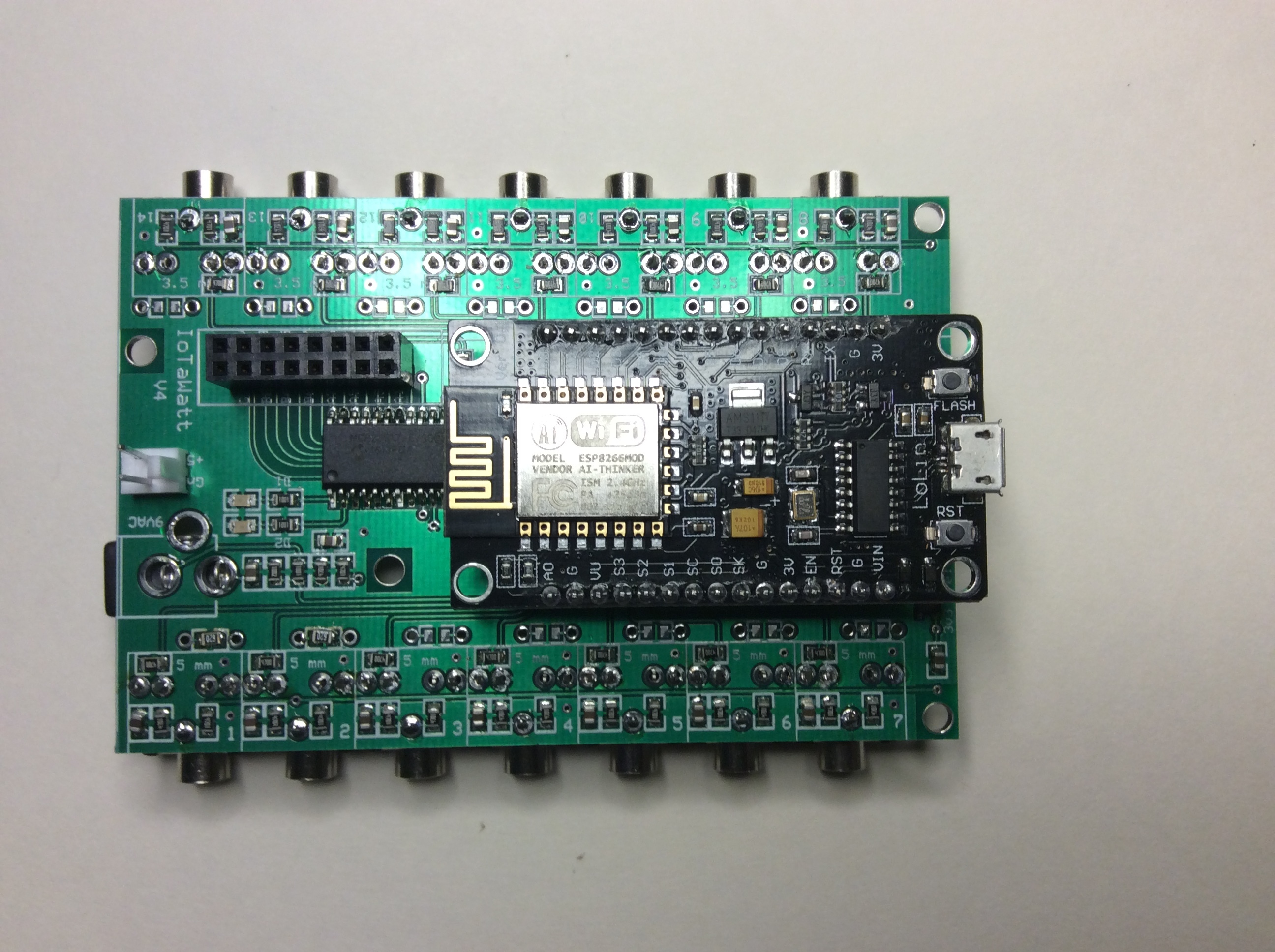
Made a lot of progress on this project in the last few weeks. First, got a new board that incorporates whatnick’s suggestion of using double headers to accommodate both the 0.9 and newer 1.0 nodeMCU. Also added an MCP23S17 16 port GPIO expander that drives two leds and offers 14 digital I/O ports. Lowered the bias resistors to 4.7K and now runs solid at about 31.8K sample pairs per second. Results seem to match my revenue grade meters within a couple percent.

The device is now called IoTaWatt - Internet of Things appliance Watt meter.


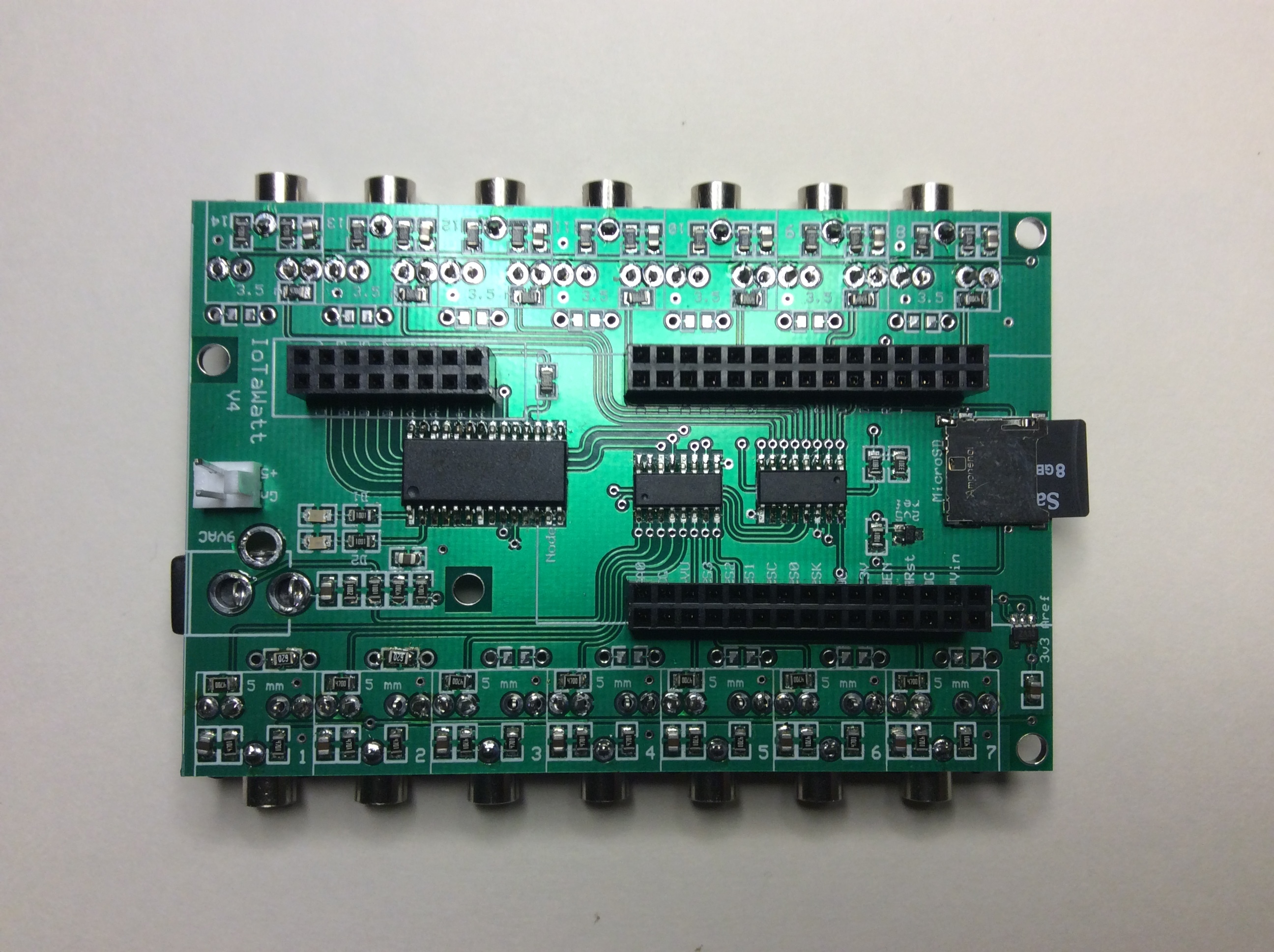
The SDcard is working well. Now the device configuration including the cloud server info and CT configuration is kept in a Json file on the SDcard. The server info including type (emonCMS for now), URL, and apiKEY are kept there, as well as the reporting frequency etc.

Will be storing the feed data and derivatives on the SDcard in the near future.
The big piece left to do is to build an AJAX application to view and modify the configuration file.

Accuracy has been the push in the last few weeks. Built a test rig that is driven by the device itself (reason for the GPIO chip). It provides an accurate calibration factor for a CT. Using a 6V AC power supply, a bank of resistors, and a set of current multiplier loops, the thing subjects a CT to up to 225 different current values from 500ma to 75A and records the CT output. Here’s the output for an YHDC SCT013-050:


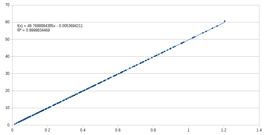
The trend line regression yields the Amps per Volt that should be used to calibrate the CT. (49.7698…or 49.8). As you can see, linearity is good throughout its range.
I’ve tested several of each that I have, including some larger mains type CTs. I’ve got a few smaller doughnut CTs coming in that I should be able to add to the Json database for easy configuration.

3 Likes

Hello @overeasy. Can you share Eagle files of your board?

I’ve posted latest schematic and PCB layout files on GITHUB (search IoTaWatt). They are not Eagle files. They are produced by ExpressPCB’s sofware which is free but as far as I know proprietary to them. I use them because the app seems more intuitive than Eagle and their protopro service (3 boards, $61US, 2 days) works well for me.

Express PCB seems to have a service to convert to Gerber format. See this post.

1 Like

You’ll probably find that the the phase error introduced by the CT across the dynamic range is a lot less well behaved than any amplitude error.

I spent a LOT of time trying to understand the effects of phase shifting. Taking more of an empirical than analytic approach, I’ve backed into a comfort zone with accuracy that pretty much ignores phase shifting.

First, here’s what you could call the net effect of CT phase error in the VT above:

The phase angle is determined as cos-1 of the “power factor” or ratio of real power to apparent power. The net effect does settle down, but realistically, in a residential power measurement scenario, the VT will typically be subjected to low currents, and therefore higher phase error.

I’ve read a few papers about correcting measurement phase error in digital power meters, and the bottom line on most of them is an empirical approach where correction tables are developed using a standard. One in particular applies the correction to the individual samples as a “phase correction” combined with an adjustment to compensate for an amplitude skew caused by the phase correction. Bottom line, it’s just an empirically developed adjustment factor. Not that there’s anything wrong with that. I think it’s probably the best, if not the only, practical solution.

In the IoTaWatt, both the voltage sense transformer and the CTs appear to have leading phase shift, so the net effect is that they tend to mitigate the each other.

To put it all in perspective, even a net phase difference of 5 degrees would yield an error from UPF in a purely resistive load of .99619 (cos 5 deg). That’s a 0.4% error. I’m seeing power factors on a purely resistive load in the neighborhood of .998 which would be about a 3.6 deg phase shift.

This deice is not revenue grade, but I’m fine with the accuracy when compared to an actual revenue grade, especially at 100 watts or more. The standard must be higher in 240V countries where the current is half what I’m measuring for the same power.

Should that say CT rather than VT? I would have expected the phase shift introduced by your VT to be more constant than that of the CT only because the voltage you’re measuring is typically a lot more stable than the current you’re measuring.

Yes, if you just look at unity power factor loads, it’s true that uncorrected phase errors make little difference to the result. But I found as I monitored more and more individual circuits it became common for the signal on any one channel to be a long way from unity power factor. This is particularly true if you’re using your monitor to measure/prune your baseload power, where a lot of devices are in standby mode. I’ve got one load where V and I are about 88 degrees out of phase. The load is pretty much all reactive and hardly any real. Add or subtract an uncorrected 3.6 degree phase error to 88 degrees and you see the problem. Add it and it becomes greater than 90 degrees and the load suddenly appears to be producing power. Subtract it and the load appears to be using a whole lot more real power than it is.

cos(84.4)/cos(88) = ~2.8

So at low PFs, an uncorrected phase error of 3.6 degrees introduces a 280% measurement error.

The latest incarnation of YHDC SCT-013-000 appears to have a particularly stable (and small, but not insignificant) phase error (and yes, according to the theory it should be a phase lead - for any transformer), but I have what I believe is an ex-equipment, specially designed phase reference transformer. I measured its phase error only a week or two ago for Glyn, and it came out at a phase lead of 0.3° at 185 V and 0.04° lead at 253 V. It is rated at 1.7 VA whereas the size is more like a 20 VA transformer. So it’s possible to make a transformer with effectively zero phase error, but at what cost I have no idea.

I think the test results in building blocks support the idea that the VT phase shift is less stable than the CT phaseshift, especially if a low value burden is used.

I have found the same, when using the shop sold 9v AC:AC and 100a CT’s with a 22R burden, on overcast days at peak consumption times. On sunny days or off-peak times the line voltage rises and the phaseshift difference increases as the lead on the VT increases but not the CT.

This is something that I have found on MHRC fan moters, at first I was being misled by the “ghost production” raising and lowering in line with the PV production monitored on the same device as I thought there was some crosstalk in the emonTx inputs/firmware but have come to realise it’s most likely the phaseshift altering with the line voltages.

It seems to me the CT phaseshift CAN be made quite stable and lower burden values provide an almost linear phaseshift, where as the VT needs some sort of correction applied to the phaseshift based on amplitude. When dealing with heavy loads or small good PF loads there is no problem, but as @dBC says tackling “vampire” loads can be.

Obviously any high inaccuracy on the smallest of loads will go mainly unnoticed when comparing overall consumption against an import meter when the accuracy of the larger loads is really good, it is however far more noticeable on the smaller consumers, especially when they start “producing” power.

I’m no expert in these fields and only comment based on my experience and the work of others here on the forum to hopefully contribute to improving the way we handle phaseshift as I’ve come to believe the VT is more of a “variable” than the CT, when correctly matched to it’s burden.

I have been following this thread with great interest and look forward to seeing your code @overeasy , I too would like to explore using the SPI ADC’s but have not had much luck with SPI in general to date.

On the subject of SPI, it’s good to read you have improved the SPI speed, would I be right in thinking that currently the SPI speed is defining the max sample speeds and adding a 3rd or 4th MCP would decrease the max SPS significantly? and that it’s the MCP’s that are determining that max SPI speeds not the ESP or the software?

Fair enough. I have to confess to having no experience with VTs. I assumed (incorrectly it would seem) that the much larger dynamic range the CT sees meant it would have the most variable phase shift.

Agreed… and the more specific your monitoring gets (for example one CT per breaker) the more exposed you become.

It all depends on the individual devices. I test the VT over the maximum possible voltage range that one can expect in the UK, i.e. the maximum range of the supply plus the maximum permitted voltage drop within the installation. In practice, the actual voltage range will be a lot smaller than 185 V - 253 V span I use, hence the range of phase error will be much smaller.

My terminology needs clarification. The plot of apparent phase shift was from an SCT013-050 which is an SCT013-000 with an internal ballast resistor (about 62ohms). Some references, and I believe on this site, call such a device a VT. Elsewhere, I refer to the voltage sensing transformer, which is the 9Vac brick that we all use to sense line voltage. While potentially confusing, I don’t think I interchanged those two concepts.

For all practical purposes in my postings, a CT is a VT. I do draw a distinction in my Json configuration files because you need to specify the burden if it’s a CT and you don’t if it’s a VT.

I agree that the phase shift of the voltage sensing transformer is more or less constant, while that of the CT (or VT) varies with the sensed current, as the plot suggests.

The range between ~230vac to ~255vac (I often see 234v to 253v as a common range) is less than 2deg. which isn’t a lot but when a 4deg lead on the CT cancels out 4degs of the 6deg lead on the VT at 235v, leaving a 2deg difference. An increase in voltage to 245v adds another 0.5deg which is a 25% increase in “difference” across a quite possible (probable?) 10v range, where as the CT with a 22R burden only fluctuates very slightly across the whole 100a range.

https://openenergymonitor.org/emon/sites/default/files/CT6-phase.svg

I would assume the VT phaseshift would be conciderably less for a similar 120v AC adapter and vary significantly across different models/brands, increasing both the need and the complexity of a correction algorithum/table.

There’s no doubt the greatest “variation” will be using different VT’s and CT’s (and burdens) but once a system is setup the greatest operational variation would probably come from the VT and a correction could be mapped to voltage amplitude for an improvement.

I posted at the same time, I was actually agreeing with you when I thought you meant the 9vac by “VT” the CT (whether voltage or current output) would probably be more stable than the AC:AC adapter in operation, or at least at UK voltages it is, not so sure about at 120v.

For me, that’s mind boggling. I was of the impression that even a .5 power factor would be a rare event in a residential setting. I didn’t see any correction for anything like that in the TX code. How is it handled there?

The IoTaWatt takes over 500 sample pairs per (60Hz) cycle, and stores the sample pairs in an array. After sampling, the pairs are processed to develop real and apparent power. Each sample pair represents about 0.66 degrees, so adding phaseshift/.66 to one of the subscripts will effectively slide the two curves in phase within 1/3 of a degree. That’s the easy part.

Determining the actual net phase error is the hard part. I have tried doing the correction in both directions for what amounts to about +/- 8 degrees. The best PF comes with +/- 1 degrees. As I venture away in either direction, it goes down. So maybe my net difference is 1 degree or nill. I cannot achieve UPF with phase shift correction at 2/3 degree increments. I cannot get closer than about .9985 or 3 degrees.

That tells me that the .998 or so that I have is coming from someplace else, like the ADC resolution at low values. After all, that’s 0.2%! When I look at the correction methods in one particular paper from a guy at TI, while it masquerades as a phase shift correction, it’s really just an adjustment based on empirical testing. Seems like the real accuracy improvement of their offering comes from kicking in input scaling at low currents to effectively increase the resolution of the ADC.

There are a couple of worn expressions that express my feeling about this:

The proof of the pudding is in the eating.
Perfect is the enemy of good.

This is interesting. I lived in a 240v country 40 years ago (Mexico City) but never developed any appreciation for the concept except that their distribution was totally unreliable.

The SCT013 based VTs that I use (030 and 050) are identical to the SCT013-000 CT with 62 and I think 39 ohm internal ballasts. As you can see from the 050 output, it’s not a lot different from the 000 with 22 ohm ballast. In fact, the 30 is pretty good as well.

If I were in a 240 volt country, I would give serious consideration to multiplying the current with loops and dividing the result. It’s either that or use lower ballast resistors and set the ADC range narrower. The double whammy of poor CT accuracy at low current and excessive phase shifting with high ballast resistors isn’t good.