emonTx with alternative CT's and 3-phase

So I finally ended up ordering one emonTx v3 together with the euro plug and one RFM69Pi.

Couple of questions!

Since building our house I ended up with 6 CT’s unused, this is due to two heat pumps not getting connected to these CT’s and 3 of them are even hooked up to the wires. Our house is a 3-phase, swedish style electrical system.

I figured I give it a chance to see if I could make use of these CT’s before buying another three :slight_smile:

Here are some pictures to explain:

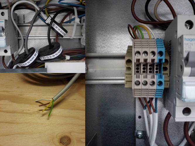
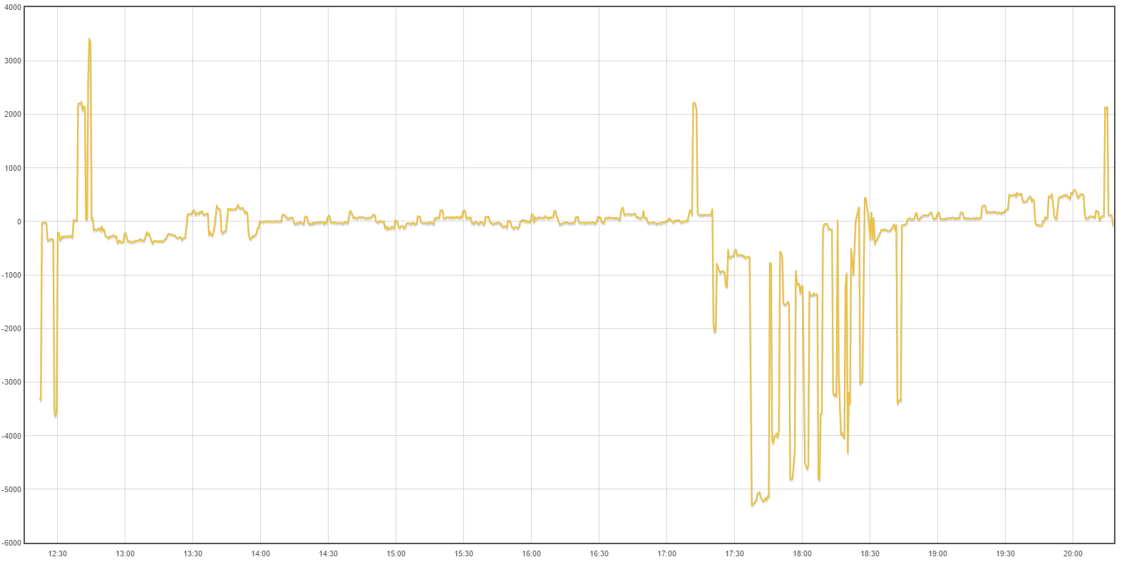
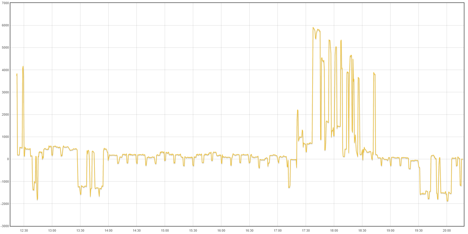
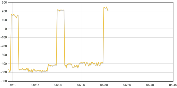
This is my CT’s connected to my three live wires, my three phases. This was intended as some kind of “phase” guards…dont ask me. I got it explained at one time but did not get the whole picture.

The CT’s are then connected to a terminal

And from the terminal outside I then find that cable inside my home.

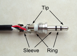
My question is, can I use these CT’s and hook up these cables to the emonTx via something like this:

If so, how many “poles” “connectors” (?) do I need for the 3.5mm jack and which would go where ?

I have then read about having to upload another “sketch” to my emonTx and for that I would need a USB to UART programmer tool i guess ?

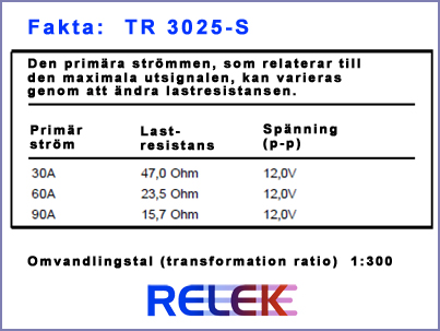
To make things worse, I have three other CT’s (looking very similar to those already connected. It says “TR 3025-S” and/or “IN09-1020-01/1013” on it.

You might be able to use those CTs with an emonTx, but without knowing more details (the only number I can read from the photo is a telephone number, which is no help) I cannot say for certain that they will be suitable. If they are suitable, then yes, that terminal block to 3.5 mm connector may be suitable, but you must check the physical size because 3 need to fit in a line to plug into the emonTx, and the centre lines of the sockets are only 13 mm apart - the terminal block must be less than 13 mm thick for 3 to fit together. You would be much better buying 3 × 3.5 mm stereo plugs and soldering the wires directly. The two wires from the CT connect to the sleeve (or GND) and to the tip (left channel of stereo audio). There is no connection to the ring.

(The picture shows the plug on the end of a temperature sensor, NOT a CT.)

The alternative CTs (TR-3025-S) http://cdn.starwebserver.se/shops/afmalmborg/files/cache/22050-stromtransformatorer-fakta_large.jpg
would be suitable but you will need to modify your emonTx if you require to measure the maximum 90 A. If you want to do this, let me know the maximum current that you want to measure and I will do the calculations for you.

Finally, to use the emonTx on a 3-phase supply, if you have the a.c.-a.c. adapter and you want to measure real power and the direction of power flow (necessary if you have your own generation - PV or hydro, say) then you will need to get and load the “3-phase” sketch, and you will need the programmer and a USB cable to do it. If you are content with measuring only apparent power (volt-amperes, always equal or greater than real power), then the default sketch in adequate.

First of all, thank you very much for your fantastic support Robert!

I found out that the already mounted CT’s are of the same model (TR-3025-S) as the spare ones I had.

So I spoke with my local electrician, it seems that I have 3 phases with each 230V and a maximum of 25A per phase. This 25A according to him was probably to high, I have a 8kW heat pump and a PV system of 7kW plus my house (dishwasher, lights etc) so…anyway. For now as I can understand, each phase has a maximum of 25A, even though as far as I can tell I will never be able to or even need to use that much current. So, given this answer, I guess I would never even reach the minimum on the specs for my CT, do I need to modify the emonTx ?

Thanks for your thoughts on the space issue connecting these three terminal 3.5mm jacks to the emonTx. Do I need to take in consideration what 3.5mm jack I would use if I buy stereo plugs, I mean, do the “cables” need to be of some kind of minimum “thickness” if you understand my question.

I did buy the a.c.-a.c. adapter so I will go on buying the programmer to load the 3-phase sketch.

Did I understand it right that the emonTx is powered by this adapter too ? Or do I need a 5V USB DC ?
EDIT: Found the answer to this last question myself! :slight_smile: EmonTx V3.4 - OpenEnergyMonitor Wiki

Yes, I think for best performance, you probably do. Recalculating the burden resistor:

Your CT will give you a secondary current of 83.33 mA at 25 A primary current. Ideally, your emonTx wants to have 1.1 V across the burden resistor at maximum current, so that gives a burden value of 13.2 Ω The burden resistor already fitted is 22 Ω, therefore you should add a parallel resistor (there are holes provided for a wire-ended one) of 33 Ω. That will give you exactly 25 A as the maximum current you can read. The calibration factor in the sketch should be changed to 22.727.
If you do not add the parallel resistor, the maximum current will be about 15 A, which I think is too low (your heat pump will account for nearly 12 A per phase, leaving only 3 A for everything else on any one phase).

Yes, they don’t want to be too thin or too thick to be hard to work with! In practice, you should be able to use the wires that come attached to the CTs and they should go into any standard 3.5 mm plug. If you are extending the wires, then the current (83 mA) is not a worry and the main and probably only risk is from mechanical damage, 0.5 mm2 equipment wire should be fine, twisted like the CT’s own wires.

The emonTx should work using the ac adapter as the power supply, but if you have a low mains voltage, it might fail and reset itself. If that happens and is a problem, you can add the 5 V USB power supply later.

Is your mains electricity a 3-wire or a 4-wire supply, i.e. is it 230 V line-neutral, or 230 V line-line? I’ve only just remembered that one of the Scandinavian countries uses 230 V 3-wire, and I cannot remember which. Because if it is a 3-wire supply, you need a sketch that is not on Github - that one is for a 4-wire supply. I’ve got the sketch you need.

Ok, so I need to add one (or more?) resistor of 33 ohm to the emonTx. There are holes for this you say. I just opened it and didn’t find it directly. Is there a picture to look at somewhere ?

Well. You are talking to a nurse :slight_smile: I dont know if the images in this wiki will help you Trefassystem – Wikipedia ?
Anyhow it states in the beginning that “you can measure 400V between the phases, (mains power - L1, L2, L3) and 230V between the phases and the NEUTRAL (phase power)” So, maybe it is a 4 wire supply after all ?

You need one per channel. The burden resistor is marked “22R0” and is immediately behind the socket, with the holes at each end. Your new resistor will sit over the top of the surface mount one.

Yes, that is a 4-wire system, so you are OK with the sketch on Github.

Perfect! I will try to find these resistors, there seems to be more than one model. Is there a specific watt to look for ? I have found for example 0.5-5w.

Do I loose something like resolution by modifying the emonTx to this 25A solution ? I trust your calculation but my heat pump rarely or never uses more than 4 kW (it has different steps).

I will try to solder this resistor without destroying something :slight_smile:

You need to choose one that will fit. 5 W certainly will not, 0.6 W should fit (check the length) and is more than big enough in its power rating. 0.25 W would also be enough, but will not be quite so readily available.

Yes, you will lose resolution. But I can only use the numbers you provide. It is normal to rate all measuring instruments to at least the capacity of the supply, but if you are sure you will never exceed some smaller value, then it’s permissible to design for that.

You should find that the measurements inherently (not including CT errors) start losing accuracy at about 5% of maximum, and by about 1% of maximum, the uncertainty, which is essentially random, is becoming quite significant. You need to decide whether this matters to you, depending on the scale you choose.

@pb66 has added (and now deleted) a suggestion that you could use more than 1 turn for the primary winding of the CT. I didn’t mention this as it didn’t look possible from the pictures, but if you can, 2 turns (passing the wire through twice) will halve the maximum current, etc.

Yeah, I deleted it as I wrote it with the standard CT’s in mind then recalled non-std CT’s were being used, when I looked at the pic’s again, the inner diameter looked a bit snug for multiple passes.

So I finally got around to add these burden resistors, mounted 3.5mm headphone jack on my original CT’s already mounted in house.

After some RPI3 bluetooth-serial-problems I managed to get the RFM69PI to receive data from my emonTx.

I have not loaded the 3-phase sketch yet because I haven’t yet bought the USB to UART programmer. It is ordered and in the mail now.

While waiting for that can anyone explain to me what I’m seeing here:

  1. -1539 Watts from CT1
  2. -1539 Watts from CT2
  3. -1539 Watts from CT3
  4. 0 Watts from CT4
  5. 252.60 Volts RMS AC
  6. 300.0°C on temp sensor1 (300 = no sensor connected)
  7. 300.0°C on temp sensor2
  8. 300.0°C on temp sensor3
  9. 300.0°C on temp sensor4
  10. 300.0°C on temp sensor5
  11. 300.0°C on temp sensor6
  12. 1 pulsecount (2 LSB’s of the “pulsecount” unsigned long)
  13. 0 x65535’s pulsecounts (2 MSB’s of the “pulsecount” unsigned long)
  14. -45db RSSI (signal strength between emonTx and the base)

Thankyou pb66!

So is something wrong here or should it be negative readings on the three phases (currently importing in the dark). Or does this have to do with the fact that I have to install the 3-phase sketch to my emonTx ?

If your AC:AC and CT’s are all on the same phase then just invert the CT orientation on the cable(s), if viewing “other” phases than the one the AC:AC is plugged into, with a single phase sketch, it’s difficult to tell due to phaseshift. Best to test all on one phase, get all 3 reading a similar and positive power, then just move L2 and L3 CT’s over to those cables without switching orientation, when you install 3phase sketch.

Been outside now, looking at my house-meter which gives me readings from L1, L2, L2. It seems like the first phase (L1) get’s read out correct. And that number is then (more or less) presented at L2, L3 in emoncms.

House:
L1: 2000
L2: 400
L3: 700

Sum 3100

Emoncms:

L1: 2340
L2: 2230
L3: 2390

Well. I will load the 3-phase sketch in a few days and go from there.

Now I have uploaded the 3-phase sketch to my emonTx! Used Arduino IDE and choose board Arduino UNO and put the rfm.ino in the same folder as the emonTxV3_4_3Phase_Voltage.ino. Everything went well i think.

Then hooked up the emonTx to my CT’s and AC:AC.

Added “log to feed” and “Power to kWh” for all node inputs.

This is images of “log to feed” from today. Can you help me understand if it is working as it should and how I should configure emoncms (or point me to where I can read about it) to see actual instant usage (sum of the three phases?) and todays import/export ?

In emonCMS, on your Input page, after you have logged that input to a feed, you can do

+input [the second phase],
+input [the third phase],
log to feed [this is the total]

If you want kWh for each feed, then, after doing the Power to kWh on the first, you’ll need to reset to zero, then do +input [ the first phase again], then add the other two phases, then do Power to kWh on the total.

So I did this, hopefully as you recommended. My concern is that this sum seems to be negative a lot ot the time. I sure have a solar PV but it is not producing anything at night for example…

I need to verify this but I think the CT’s are hooked up on three phases going in to my house and not the actual cable that exits the house (and have the solar pv attached to it). What I mean is what I am measuring right nog would probably be positive all the time right ? Only import. I need to talk to an electrician to move the CT’s.

Anyhow it should me positive readings i guess ?

How can I start to look for errors, is one or more of the CT’s in the wrong direction ? Is the error from me using the same ground for all three CT’s ? Me not understanding emoncms ? Anything else ?

Obviously, I do not know exactly how your house is wired, nor how you have installed the CTs. All I can say to help you is that you must get the basic information for each phase correct as it comes from the emonTx, or at least understand how and where it is wrong, before you worry about emonCMS.

Your problem seems to be where you are measuring. Forget for a moment that you have three phases. There are 3 quantities that are closely related, Nett grid power, Used power and Generated power. Knowing two, you can calculate the third.
Nett grid = Used - Generated
But you must know, or assume, the direction of power flow to get the sign of the power correct, and that’s where the direction that the CT points comes in. We count Used and Generated as positive (so your inverter consumes 50 W, or ‘generates’ - 50 W, at night when it is dark), and imported Nett grid as positive.
Therefore, where you measure current tells you which of the three versions of that formula you need:
Nett grid = Used - Generated
Used = Nett grid + Generated
Generated = Used - Nett grid

You should be able to deduce what each CT is measuring if you know, or you can reasonably assume, what it ought to measure given a particular set of conditions. You will probably need to turn appliances (and your PV) on and off while you make measurements, and record the results.
Note, you do not need to get an electrician to reverse the CT, you can put a minus sign in the sketch.

I will read your thoughts over and over again and try to find a local person who can explain things for me. I will be home tomorrow to look closely where the CT’s are situated. My guess from looking before is that they are located on incoming cables to my house. My PV inverter is mounted in my garage which is outside the scope of the cables where the CT’s are currently measuring. Thus giving only “positive” readings would make sense to me because I don’t have anything else in house except for consuming products. These low numbers of negative readings must be some sort of error if you ask me.

I’ve just read this Zero consumption calibration and all of this confuses me but I got some kind of feeling this guy has had the same issue as I’m experiencing right now.

Anyway, thank you for helping me with this!

That is possible. If there is no current input to your emonTx, then you might measure some small power due to electrical noise. 240 W is about 1% of the maximum that you can measure, I would expect the noise to measure less than that.
I have the sketch running here, with only one CT which is not near a cable, and I am seeing a small current and very small real power (3 samples):

Voltage: 249.62 Phase 1: 0.00 A, -0.01 W, 1.14 VA, PF=-0.006 Phase 2: 0.00 A, 0.00 W, 0.00 VA, PF=nan Phase 3: 0.00 A, 0.00 W, 0.00 VA, PF=nan Input 4: 0.00 A, 0.00 W, 0.00 VA, PF=nan Temperatures: 26.80 27.10 20.30 Pulses=1
Voltage: 249.58 Phase 1: 0.03 A, 0.28 W, 6.93 VA, PF=0.041 Phase 2: 0.00 A, 0.00 W, 0.00 VA, PF=nan Phase 3: 0.00 A, 0.00 W, 0.00 VA, PF=nan Input 4: 0.00 A, 0.00 W, 0.00 VA, PF=nan Temperatures: 27.10 27.30 20.30 Pulses=1

Voltage: 251.34 Phase 1: 0.00 A, -0.01 W, 1.15 VA, PF=-0.011 Phase 2: 0.00 A, 0.00 W, 0.00 VA, PF=nan Phase 3: 0.00 A, 0.00 W, 0.00 VA, PF=nan Input 4: 0.00 A, 0.00 W, 0.00 VA, PF=nan Temperatures: 27.20 27.50 20.30 Pulses=1