I have emonTx with 3x CT and running 3-phase firmware (living in EU with 3x 25A input). I have successfully calibrated it by connecting resistive load and all CTs to the same wire.
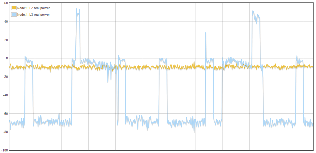
However it seems that the calibration is not sufficient for tracking small loads. If I understand it correctly, I should not have a negative real power (and negative power factor) at all. But my L2 and L3 graphs seem little biased (see here Dropbox - 2016-11-05 19_11_52-Emoncms - graph.png - Simplify your life )
The question is how to correctly calibrate for zero consumption. Should I just add +10 in emoncms feed for L2, so that it doesn’t go input negative power? Or should it be somehow calibrated on emonTx level?
Bonus question: does the polarity of real power depend on how is the AC-AC adapter “polarity”? I thought that I installed the CTs in opposite direction so I changed it in firmware, but then re-plugged the AC adapter (maybe in other polarity) and I again got negative values. If it so, then I is maybe good idea to document it somewhere.
Your “consumption” at zero or very small loads (you don’t say what “small” is, but 25 A is only 25% of maximum anyway) is most likely due to either noise or pickup from adjacent conductors. If 10 W (presumably) concerns you, then you are free to add a constant in the input processor in emonCMS, or in the emonTx. It makes no difference where you do it.
Of course it does. It has exactly the same effect as reversing a CT. It is the relative orientation of VT & CT that is important, because in practical terms, there is no such thing as absolute phase. We in the UK use polarised mains connectors so it not possible to plug the adapter in the wrong way round. It is mentioned in the installation & calibration instructions (I have checked).
Thanks for your fast reply. Yes, I understand that the measurement around zero is prone to noise. 3x 25A is the circuit breaker, it seems that my “idle” (when I’m not at home) consumption is below 80W (over all 3 phases), which is quite low for 100A CTs. I am also considering changing the burden resistors, but at least on my PCB the holes for non-SMT resistors are filled with solder, so it will take more effort to install them.
So if L2 is “offset” below zero, when I add L1+L2+L3 real power, it will reduce the total. And if I don’t have any solar or other generator, anything with negative power factor is error. So I’m concerned about this zero error just because of correct sum of L1+L2+L3. I have attached the graph now (just few devices at standby and refrigerator)…
Is the real power negative because of error in current measurement, or because of error in phase measurement? So is it better to compensate it in current, phase, or resulting real power?
No, it is an ac-ac adapter. The output is actually about 11.6 V a.c. (It is 9 V on full load, which it never sees.)
The 3-phase sketch delays the voltage wave by ⅓ and ⅔ cycle so that it is in phase with the current in L2 & L3. An error in setting that delay cannot invert the direction of power, unless that error is huge, therefore I have to think that your CT for L3 might be picking up genuine current from L1 and L2 - if those two currents are equal, then their vector sum is in exactly the opposite direction to the L3 current, and that would produce a negative real power. It is a remote possibility but a possibility nevertheless.
I do not think internal noise from the 328P itself could account for 70 W. I have this minute set up an emonTx V3.4 with 3 CTs and the UK adapter, and with the 3 CTs well away from any mains cables, I am seeing random currents of below 0.05 A and random powers mostly within the band ±0.5 W, though I did see one peak of just over 1 W.
So, since currents in the other lines are basically not enough, and neither is noise, I think I would look for the source of a magnetic field, which your CTs might be picking up.