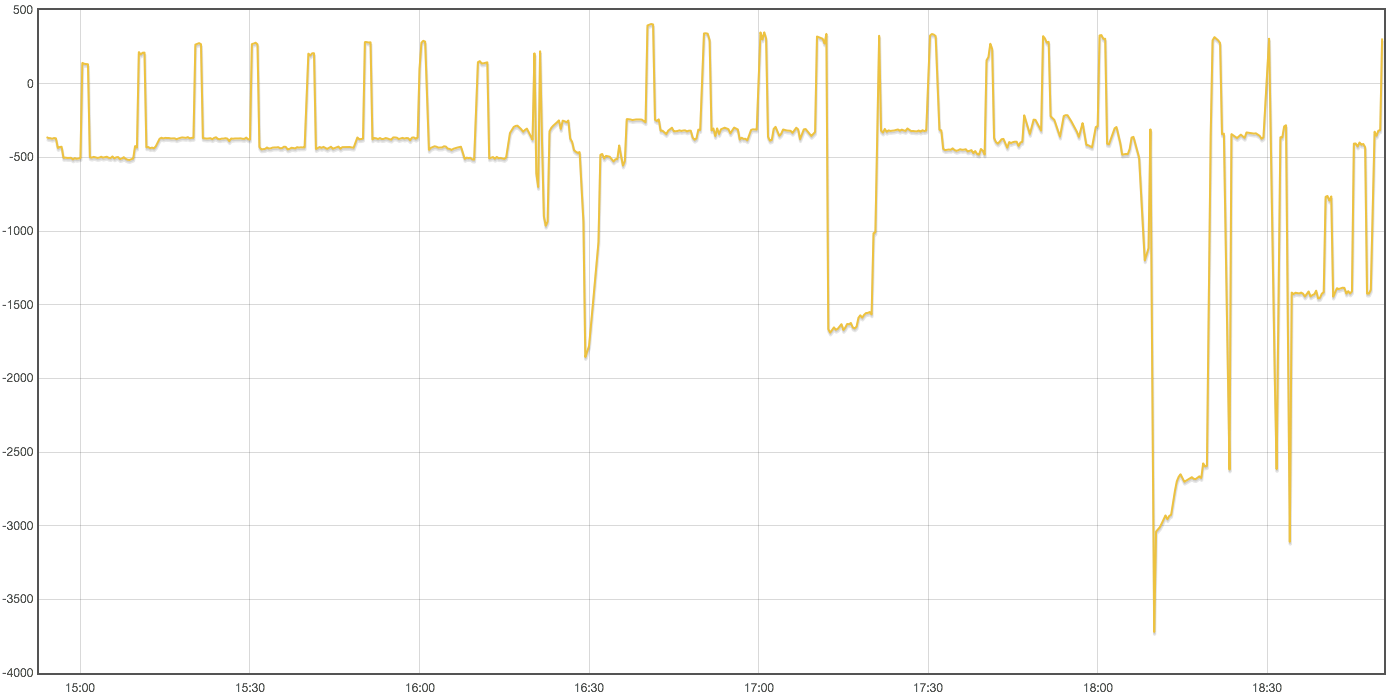
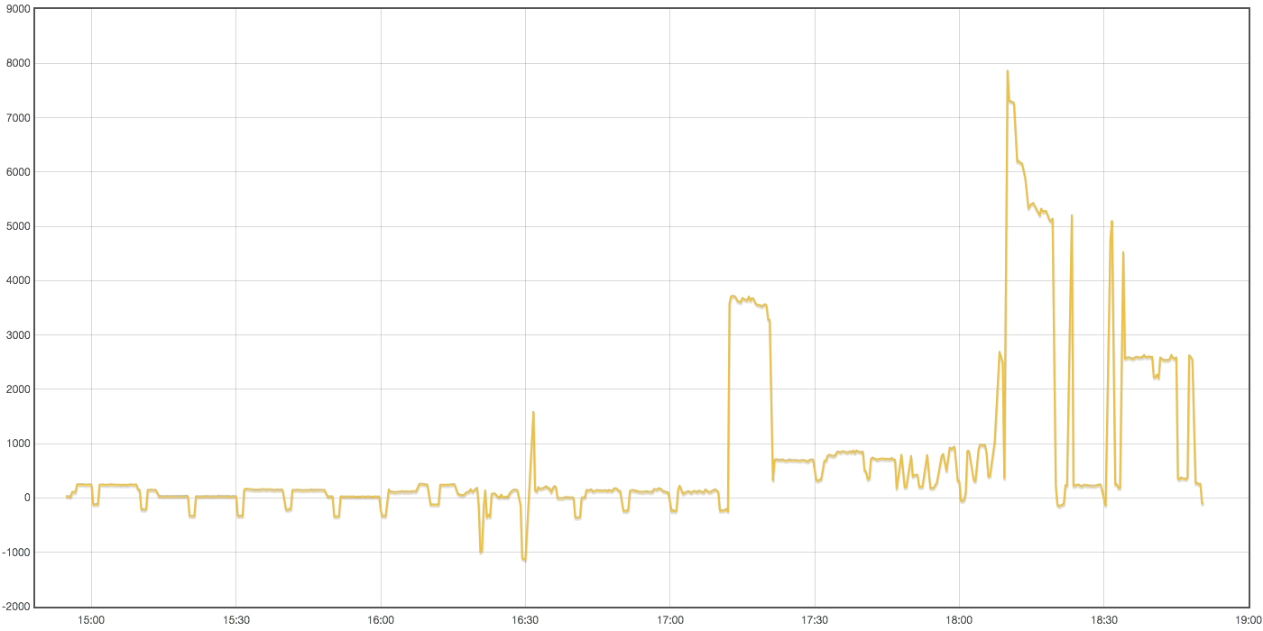
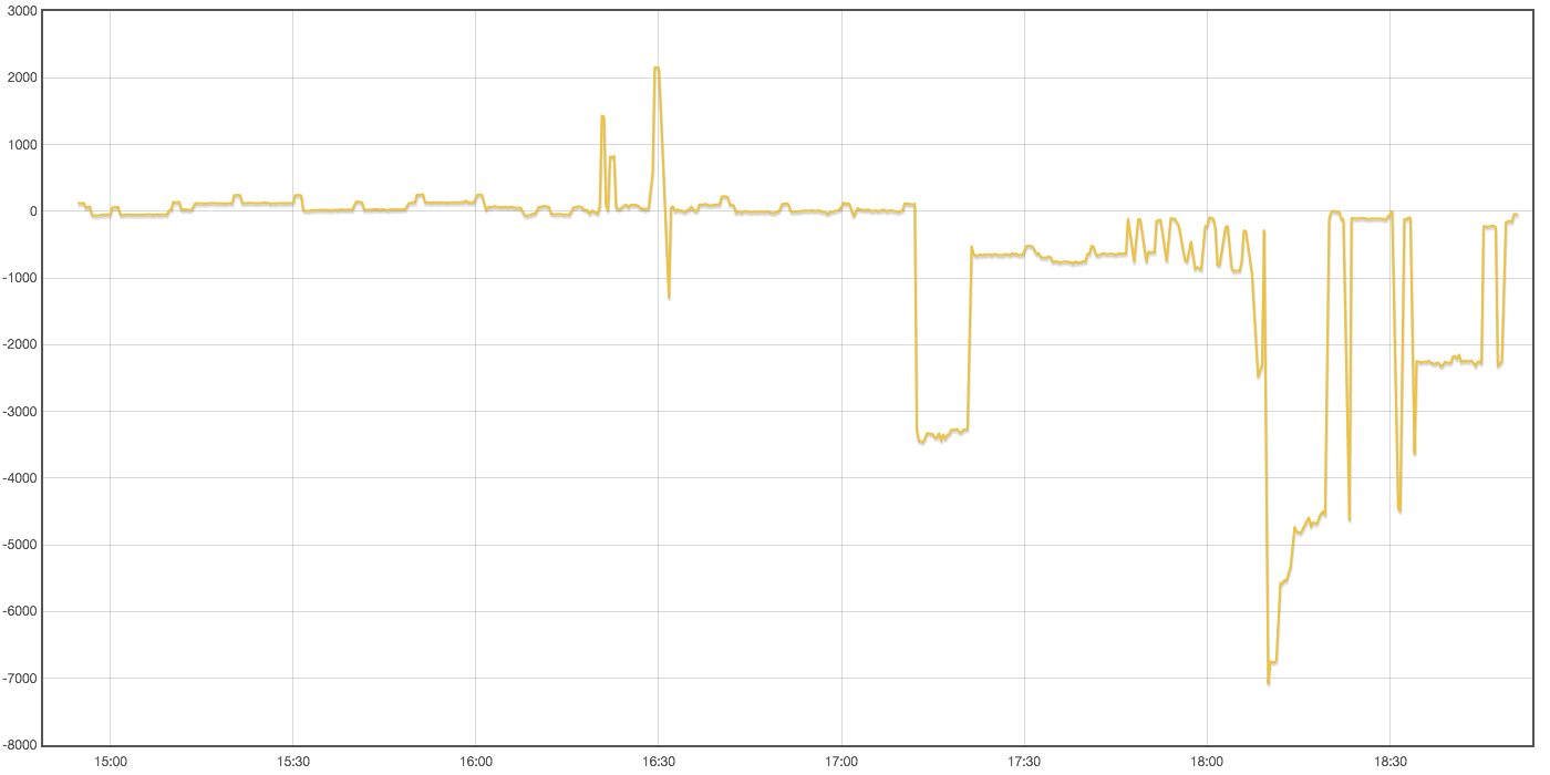
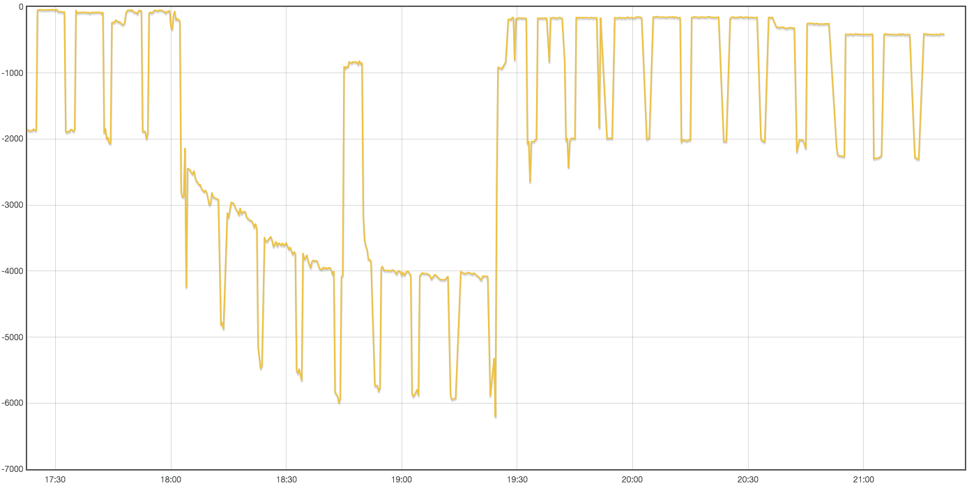
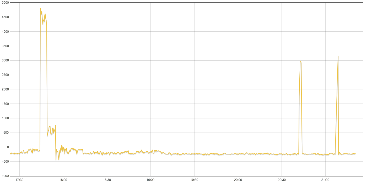
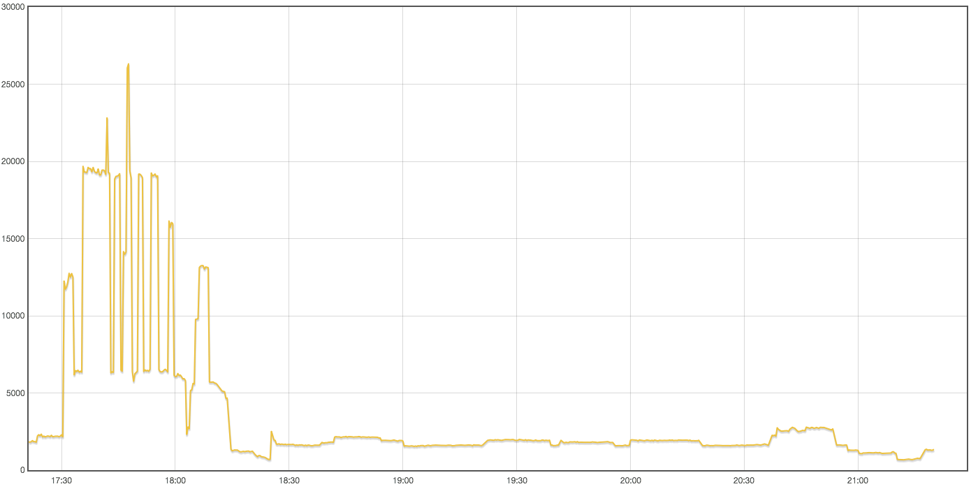
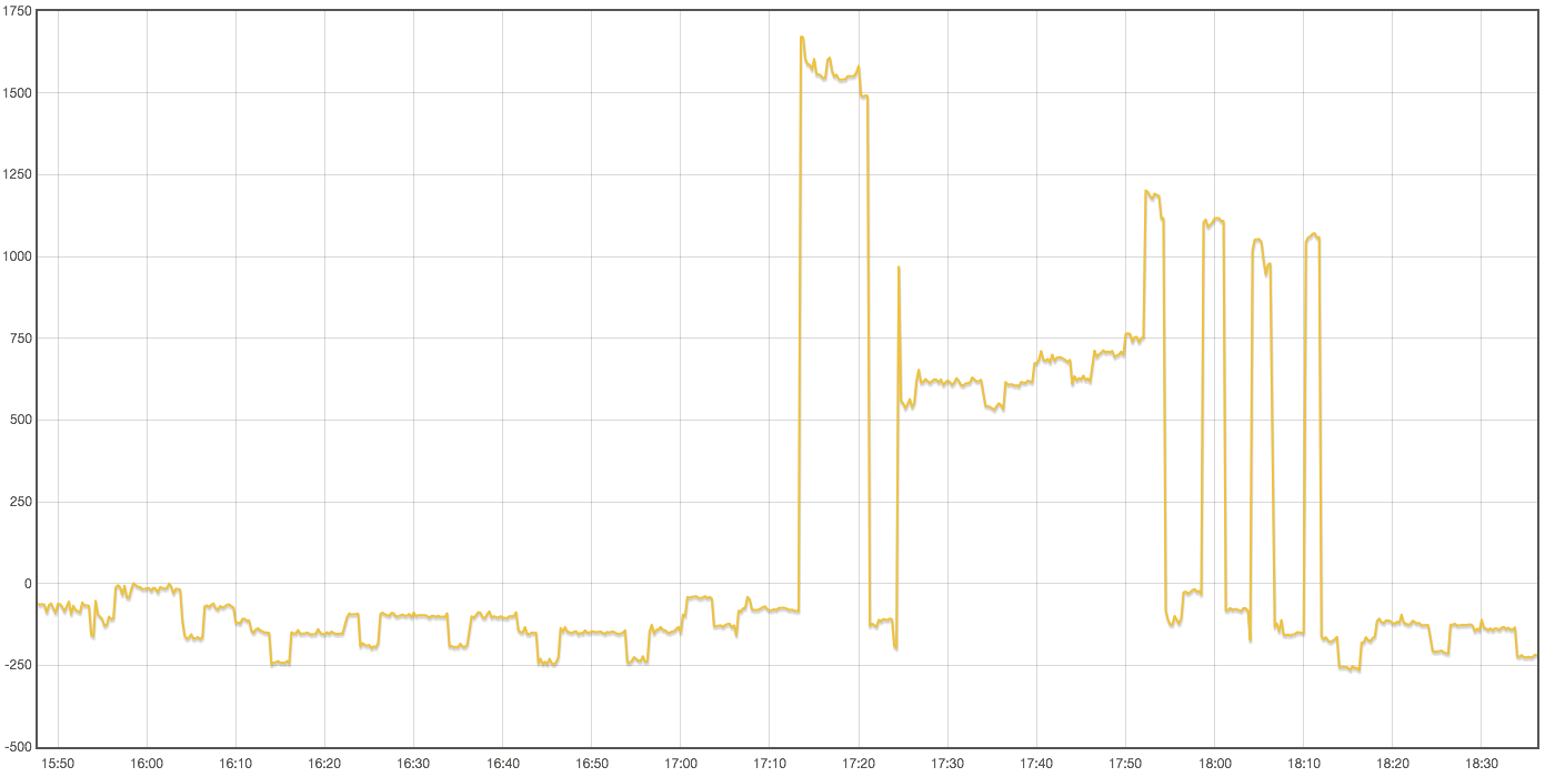
Ok, in my installation there seems to be some big problem according to me, not just noise or “error”. Looking at these images from 15 to present - today reveals some measurement going on and around 17-18 this evening you can see some cooking taking place probably (and number around 3-5000watts is probably right). But two of three phases are mainly negative and one of them is slightly negative but mostly above 0. What could cause this ?
The “Power to kWh of three phases” - log sums up to -1.5 in these three ours.
Until you have your CTs in the correct places, anything you measure could be wrong.
I do not have a 3-phase supply. But on a single-phase test load, the sketch can be calibrated to give the expected “wrong” values, and others have reported that the sketch works for them, so - disregarding small errors that are unavoidable with the emonTx - I think the sketch works as intended.
Can you photograph your CTs now with a bigger picture so that I can see where the wires come from and go to?
If you have a CT on the wrong phase, or facing the wrong way (or the wires are swapped), then you will get a negative reading when it should be positive.
If your CTs are on the supply side of the place where the PV joins, then if your PV is generating, you may (correctly) have negative readings.
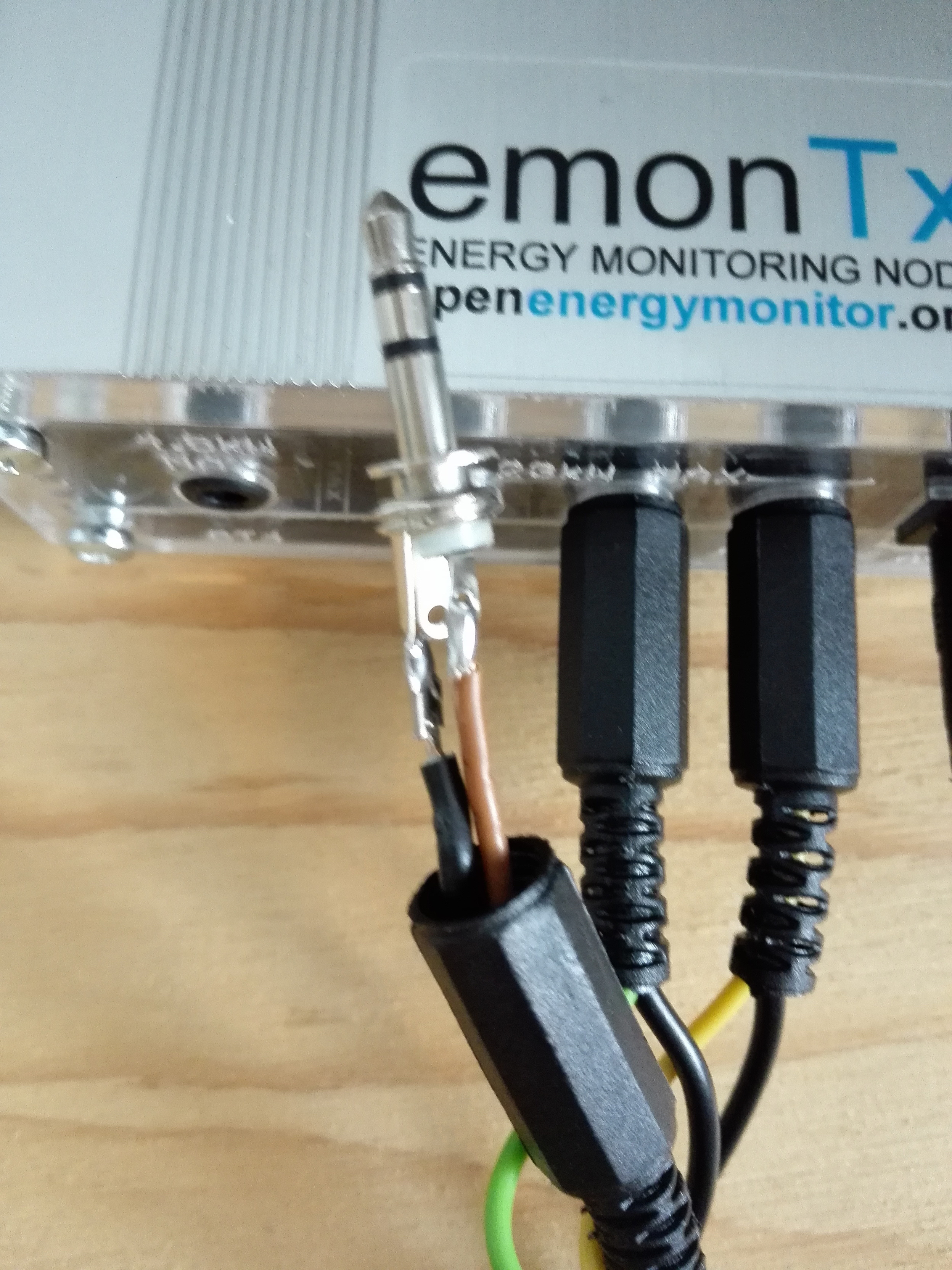
I see from the photo that the blue wires from the CTs are connected, and go to the white wire into your emonTx. That white wire must connect to the TIP of the jack plugs for the emonTx, which is the ‘earthy’ side of the input; and the brown, green and yellow wires to the SLEEVE. The way that the CTs are wired is bad practice, ideally each should have had a twisted pair of wires all the way to the emonTx.
[Edit]
Having now checked with a simulation, if you have made the common connection to the sleeves of the emonTx plugs, then you will certainly get undesirable interaction between the inputs.
Unfortunately, this would be the way I, and I think anyone, would expect to wire the plugs, but because of the way the socket is wired so that the built-in switch can be used to signal “no connection”, it is wrong.
In general, yes. In your case, if you wire it as I say (white wire to the plug tip), it should be good. Otherwise, you are putting approximately the same signal on each input of your emonTx.
I really must write a “learn” page about extending the wires to a CT.
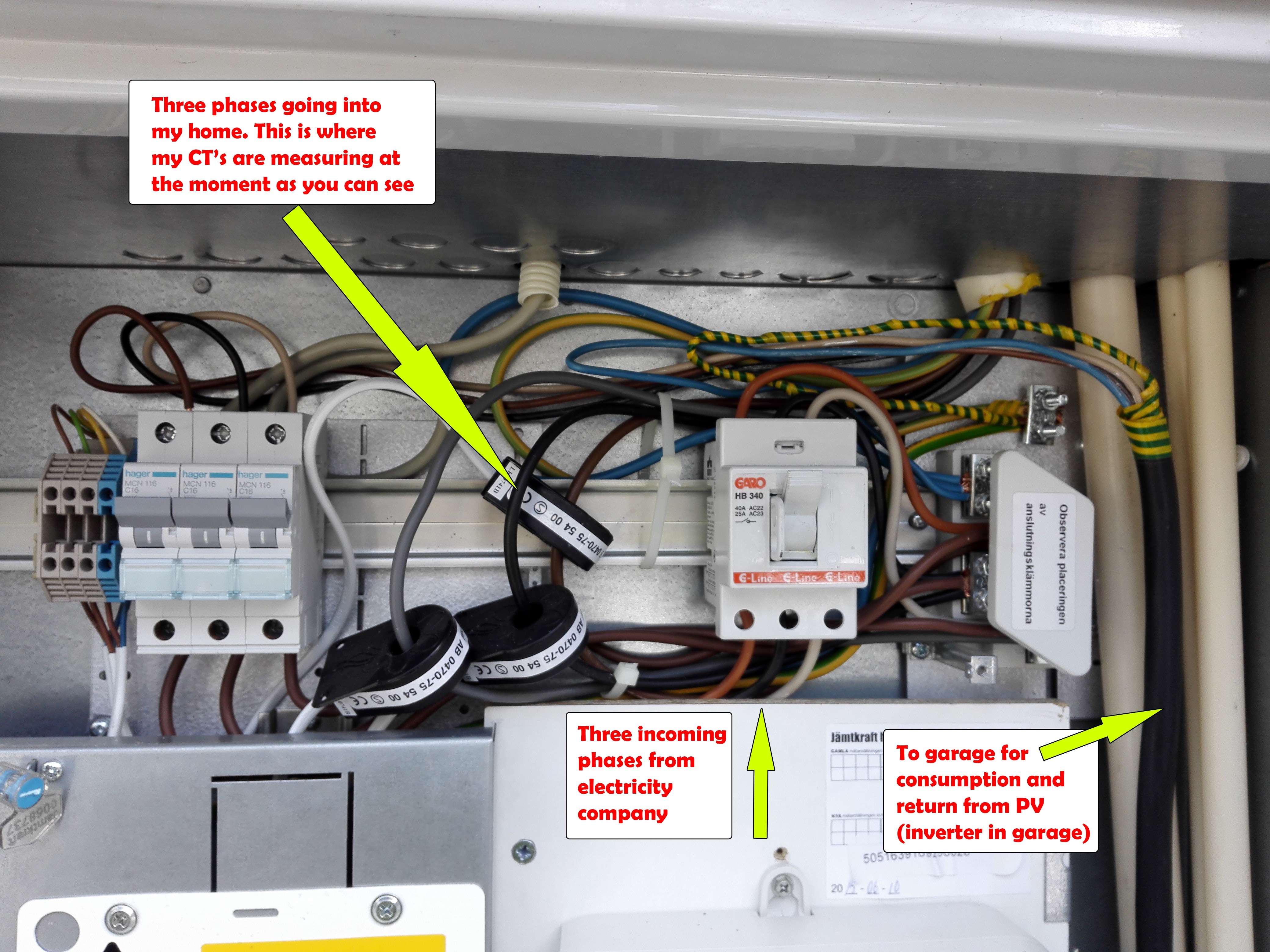
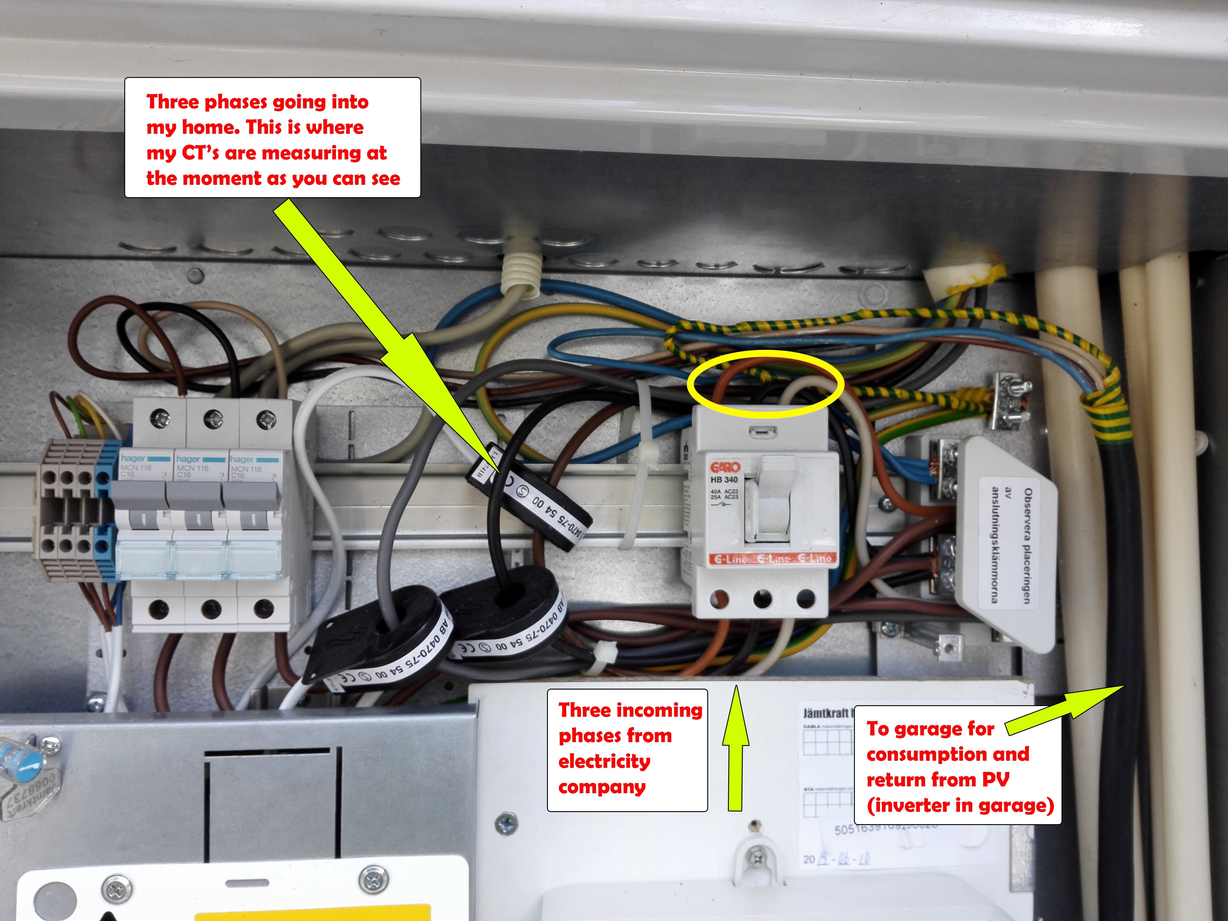
Here are two pictures to explain more in detail how my house and CT/emonTx is wired. Sorry for the bad picture on my emonTx. It should be wired as you suggested with the “signal” cable to the tip and the GND from CT to SLEEVE.
Thank you. I think your PV comes via the 16 A Hager m.c.b’s on the left, and the white box that is open is the place where the PV joins the house supply. I looks as if your c.t.'s are on the house supply, so you will not measure the PV contribution.
So - everything looks correct, except for the connections at the emonTx. You must swap the connections, so that the brown, green and yellow wires go to the sleeve, and the common black wire to the tip. When you do that, I think everything should work correctly, and emonCMS will record your house consumption. The emonTx will not see the PV generated, and it will not see garage consumption.
Great. So I misunderstood the connection of TIP and SLEEVE of the 3.5 mm connector.
I did read the instructions from you about connecting the CT to the 3.5 mm connector in the beginning of this thread couple of times but ended up thinking that GND would be SLEEVE.
Anyhow when I get around moving the CT’s to the incoming wires from the electricity company I guess it will measure the total import / export including house, pv and garage ?
That is what anyone would expect, but when you look at the circuit diagram of the emonTx, you will see that it is wrong. I can easily understand why you got it wrong.
Yes, that is correct. When your PV generated exceeds your house + garage use, power will be negative. The rest of the time, it should be positive. If it is the opposite of that, you will need to multiply by -1 inside emonCMS, or reverse the c.t.'s on their cables.
The good thing is that the 3 inputs are now showing very different numbers. So we are doing something right!
Did you change the burden resistors in your emonTx, and the current calibration constants, as in post no. 4? If you changed one and not the other, that would account for the current being wrong. Is the power about 4 × too big? If yes, that is the wrong calibration constant in the sketch (90.9 → 22.727).
I cannot see a reason for the negative power, but there might be one. Here are the things that could make it wrong:
The CT in input 1 is not on the same phase as the a.c. adapter.
The 3 c.t’s are not in the correct sequence.
The c.t. is reversed on it’s cable (but it looks right to me), or it has been made or labelled wrongly.
You need to be careful with the phase colours, because I can see several wires in your photo which are wrong. e.g. the wires from the PV are brown, black, grey above the m.c.b. but brown, brown, brown below it.
The phase sequence should be 1 = brown, 2 = black, 3 = grey. But for the emonTx, whichever phase the a.c. adapter on is defined as 1, then the others follow in order. But beware: I wrote “should be” - it is not unknown for electricity companies and installers to get it wrong.
Fantastic, we are advancing. I’m very sorry, I had forgot or not read correctly about calibration in the sketch. This is now done. I also have identified the right phase-order, brown, black, grey and connected them in order 1-2-3 on emonTx. This gives me the most correct readings so far! I still have some negative readings on all three phases but they seem to reflect my actual usage more than before.
One of your possible reasons for negative reading, the one about the AC:AC adapter not being on the same phase as input 1. Might this be the final problem ? I mean, is it obligatory to have the AC:AC adapter on the same phase as input 1 on emonTx? I have tried to look inside my house where all the electric cables are distributed but it is hard or impossible for me alone to understand which phase supplies what part of my house. I then need to ask someone.
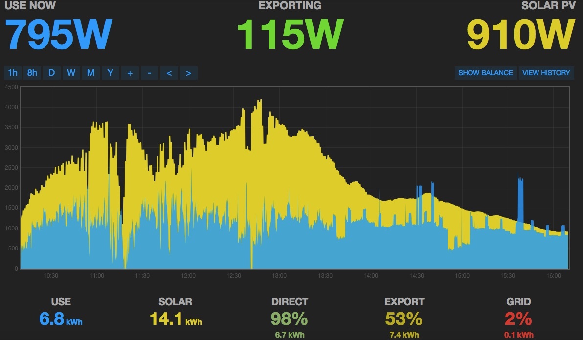
This image is a sum of the three phases log to feed’s.
Yes it is - as the sketch is written. But as I wrote earlier, the emonTx’s Phase 1 does not have to be Brown, it can be any phase, as long as the next two phases follow in the correct sequence.
If you can look inside your distribution board, ideally you will find that the circuit breakers are marked, or you might be able to see how the busbars are arranged. The breakers might be grouped by phase, or maybe every third breaker will be the same phase. I assume you will not be able to isolate one phase at a time and see what goes off?
[Edit]
I forgot to mention this: You will of course read zero volts (or very nearly) between circuits on the same phase, and 415 V between circuits on different phases. But that will only tell you which circuits are on the same phase, it cannot tell you the phase sequence.
When you put it like that again I had an “aha” moment and realized that I probably might be able to keep the nice L1-L2-L3 order I arranged today and just move all three inputs one the emonTx one step at a time instead of searching what phase the AC:AC adapter is connected to. And there it was, two steps to the left and I now have what I can tell good readings!
All three inputs positive and around 500-1000 watts which seams reasonable right now.
I’m sorry to say but I still need your help. I had my electrician come by and move the CT’s to incoming feed from the electricity company as shown in the yellow circle in my attached picture (be advised, image is the old one). I was very clear to him about moving right CT to corresponding phase and not turn them in the other direction. As far as I could see, he did what I told him The flattest surface on my CT’s are still pointed in the direction of the load.
After that I got what I thought was right, negative readings during the day when producing electricity with my SolarPV.
Started playing around and making calculations with the feeds to get net-usage in my house/garage. So far all well.
Problem started when night fell, I noticed that my house where consuming 2-3000w (by looking at my main-meter and using common sense) and emoncms was reporting only 800-1000w. Looking at my three phase-feeds 1 or 2 gave negative readings.
So…moved the inputs on my emonTx back and forth like before. Not changing phase order. Still can’t get readings to sum up like I want to. That is - in the evening and night to be all positive and between 800-2500w (heat pump consuming approx 2000w).
Do you have any ideas ?
EDIT: After moving CT’s, they now include my garage where the SolarPV inverter and heat pump is situated, my garage has it’s own distribution board. The heat pump is three-phase and is rated to 6-8kW (?) but uses 2kW 98% of the time I would say.
I need to think about this. Either what you thought was correct was in fact wrong, or your electrician cannot have done what he intended to do (and what you thought he had done).
My first thought: did he exchange two of the c.t’s, so that the phase sequence is again wrong? If that is what has happened, moving the c.t’s around the sequence will not help - which I think is what you have found.
Your thoughts are more or less what I have been thinking about myself.
That is, either I was wrong from the beginning that everything seemed to work as intended or that the phase sequence has changed. Because of my lack of patience I did not document exactly how the input where made when I “thought” I had it working.
Anyhow, my phase-sequence right now is: L1: brown, L2: green, L3: yellow (colors are those of signal cables from the CT’s).
And troubling is, I am pretty sure that this sequence has been tested yesterday by me, and shifted along input 1-2-3 several times without good readings.
So, me being able to accurately measure what phase the AC:AC adapter is on would be important at this moment I guess ? If it is found and I still have strange readings we need to ask you or the community with higher knowledge if it can be done ?
EDIT: I took a quick look at input 1-2-3 from this night. 1 and 2 is up and down between approx. -500 → 500w while input 3 is constantly positive between 300 and 1000w. A normal night would be between 800 and 2500w i guess in totalt i guess. All phases seems to show different numbers though. Also, I did change the input from being in phase-order to not being in phase-order, but not organized, more or less to test and se if I were lucky…could there be 9 possibilities ?
This is just fantastic. Isn’t it I don’t think my usage is that low but anyway, when this error gets fixed. I love this peace of software and hardware.
You can use one of Robin Emley’s test sketches for his diverter. This will show the relationship between voltage and current, for one input. (You will need to do some editing.)
It will draw a graph (using the Arduino IDE’s serial monitor) of voltage and current against time. You need a resistive load (electric kettle, convector heater without a fan) for that, and you need to move it around your house until it is on the correct phase.
Voltage (V) and current (c) should be in phase for Input 1. I have only posted here half of one cycle:
cycleCount 304,  samplesRecorded 229
|                                     vc.                                       |
|                                       c  v                                    |
|                                       .c    v                                 |
|                                       .  c      v                             |
|                                       .   c         v                         |
|                                       .    c             v                    |
|                                       .     c                v                |
|                                       .      c                   v            |
|                                       .       c                    v          |
|                                       .       c                     v         |
|                                       .       c                     v         |
|                                       .       c                      v        |
|                                       .       c                      v        |
|                                       .      c                      v         |
|                                       .     c                   v             |
|                                       .    c                v                 |
|                                       .   c           v                       |
|                                       .  c      v                             |
|                                       .c   v                                  |
|                                       c                                       |
Here, my c.t. is reversed on its cable:
|                                     v c                                       |
|                                      c.  v                                    |
|                                    c  .     v                                 |
|                                   c   .         v                             |
|                                  c    .             v                         |
|                                 c     .                  v                    |
|                                c      .                      v                |
|                               c       .                          v            |
|                              c        .                            v          |
|                              c        .                             v         |
|                              c        .                              v        |
|                              c        .                              v        |
|                              c        .                              v        |
|                               c       .                             v         |
|                                c      .                         v             |
|                                c      .                     v                 |
|                                  c    .               v                       |
|                                   c   .         v                             |
|                                     c .    v                                  |
|                                      cv                                       |
To test Input 2, you must change line 19:
byte currentSensorPin = 2;
The current should lag the voltage by 120° (⅓ of a complete cycle)
(Time increases from the top of the page towards the bottom, so the current should be shifted down the screen.)
To test Input 3, you must change line 19:
byte currentSensorPin = 3;
The current should lag the voltage by 240° (⅔ of a complete cycle) - or lead by 120° (⅓ of a complete cycle).
I do not have a 3-phase supply, so I cannot show you what it should look like.
Wow, interesting. I will try to see of I can manage this test.
It all boils down to finding out what phase the AC:AC adapter is connected to and then put that phase on input 1 and then find out the right phase order for input 2 and 3 ?