I’ve searched a lot now, but am still unsure if this is possible, and it so, how it can be done.
I want to monitor current of three phases (SCT clamp sensors) and voltage (ZMPT sensor), all outputing voltage.
This works fine if i use the single analogue input of the wemos, but as it has only one, it used the external ADS1115 connected via I2C.
Does emonlib still need the analogue pin entered in the sketch - eg. emon1.current1(1, 111.1), or is there a workaround for the ADS1115?
Any help really appreciated. Thanks!!
You might want to have a look at this thread (especially post #23):
Bottom line is the ADS1115 is too slow. (max sample rate of 860 samples per second)
Thanks Bill. I know that thread, and went through it. Unfortunately it’s above my knowledge to understand what all this sampling rates really mean, and what issues they impose.
Bottom line seems to be, that emonlib and ads1115 are not working (well) together.
So i will need to look into some other way of sampling and averaging the results.
I just rethought it: Am i correct, that the essential and time sensitive part of measuring is the VOLTAGE? Then i could use the analogue pin of the wemos to do that and connect the 3 current sensors to the ADS1115? And then it should be simple mathematics? Or do i oversimplify this now?
No, not just the voltage - you need to measure both voltage and current.
The way we do it in emonLib is voltage and one current are measured alternately, and the Arduino / Atmel 328P can measure about 50 pairs of samples during one cycle of mains, so about 2500 sample pairs per second. It does that and samples for 200 ms, then repeats for the next c.t, etc.
Using the same processor but operating the ADC inside it in a different way, emonLibCM measures the voltage then a current sample for each c.t. and in this configuration it can measure 1900 sample sets per second - continuously.
Now you need many samples per mains cycle so that you have a reasonably accurate picture of the shape of the wave. That’s not all that important for the voltage, because it’s a reasonably accurate sine wave, but the current waveform, especially for something like an LED lamp or a computer power supply, will be anything but. So to calculate the power accurately you need a lot of samples in each mains cycle. Theory says that you need at least two samples for the highest harmonic frequency you’re interested in, and that should normally be about the 15th, which is 750 Hz, so you need more than 1500 samples per second.
EU regulations put strict limits on the amount of power you can have in the harmonics, and the higher the harmonic, the less you’re allowed.
Sometimes a picture (or two) helps… ![]()
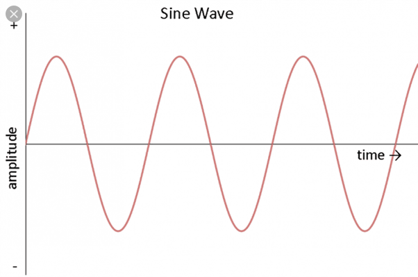
Here’s what a clean sine wave should look like:
Note that this is an ideal sine wave. The mains voltage waveform isn’t quite this “clean” i.e
it is distorted, and the amount of distortion varies depending on several factors.

If the sample rate of an Analog to Digital Converter is too low, the waveform gets distorted.
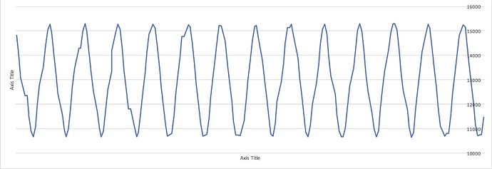
This is the picture from post 23 in the thread I referenced:

Compare that to the “clean” waveform above, and it’s easy to see the distortion.
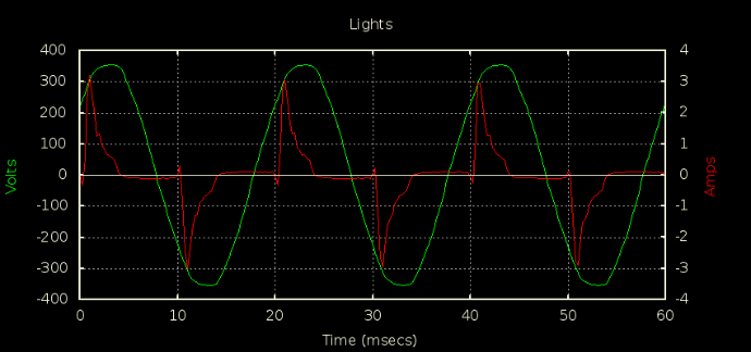
If a clean sine wave gets mangled like that, a current waveform like dBC’s
compact fluorescent lamp load (the red trace)
is definitely not going to get reproduced correctly. Result, poor accuracy.

WOW. Thanks for the long answers and insight. Very much appreciated.
I understand that for a precise number you need a lot of measurements as the waveform is very dirty. But in my simple mind i compare it to the usage of a DMM: I measure AC voltage: It shows a value of 219.3, 220.5, 221.0, 220.3 … So quite stable 220V with a deviation of +/- 1V or ~0.5%. I now get this value from monitoring my single analogue pin with “emon1.voltage(0, 614, 1.7)” and serial monitor shows those 220V.
If i now average the measurement of the ADS1115 for 1s (with 20 measurements/s) I get quite stable readings of several amps.
And i assume that I’m wrong if i assume that these are “precise enough” measurement (in the range of a “kill a watt” device)? That’s all I would need. A rough estimate of the power my house needs. I don’t want to challenge the power company proofing that they charged me too much or something like that 
As is understand it emonlib does an excellent job in internal calculating, averaging and cleaning the reading your get from the sensor and allows easy reading and access. If it try to acchieve this somehow else I would surely massively fail. I also tried using and Arduino and transferring that data to the esp8266, but this was an even bigger desaster. 
Well, reading your posts a second and third time I guess my approach will fail … 