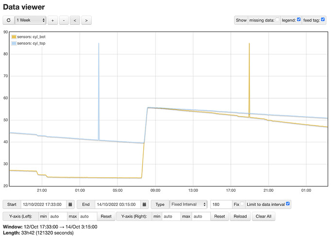
Seeing similar spikes on two sensors, upper and lower DHW cylinder pockets. Consistently takes temp to 85.0 on each sensor. Timing seems random. Any ideas? thanks
Those don’t look like @Nikall’s spikes to me. They look more like genuine spikes. I’d suggest starting a new topic, since I don’t think your spikes have anything to do with the current topic. Also you didn’t say what type of sensors they are nor what they are connected to and how.
If we’re talking about DS18B20 sensors, they are not even genuine spikes, they are genuine values coming back from the sensor, error values. 85.0 °C is the value the sensor’s memory is initialised to when it is powered up. If it doesn’t get the message commanding it to “convert” the temperature into a reading, then the next command, which is to send the reading over the bus, means it sends “85 °C”.
So for some reason, the sensor didn’t receive the first instruction. I’d first check all connectors and joints. How old is the installation, and how far apart are the sensors from whatever is controlling them, and how are they cabled? One-wire is a (relatively) high speed data bus given the types and lengths of cable that it can be used over, so the information @djh requested is important.
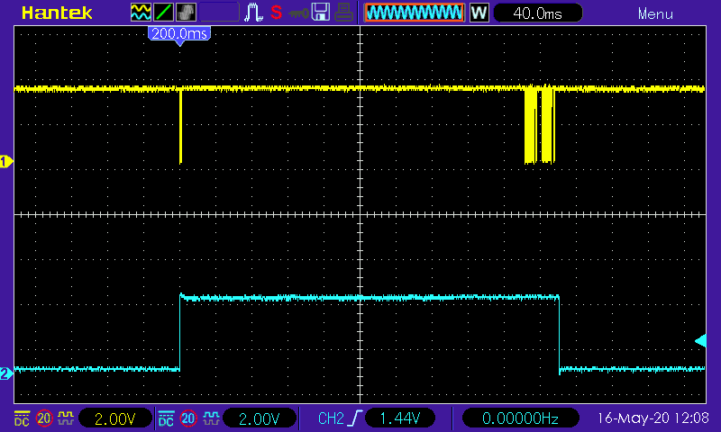
emonLibCM uses the One-wire bus like this. The yellow trace is the One-wire bus, the blue is a digital output to trigger the 'scope.
-
Overall view. The first bus signal is “convert”, the two sensors are individually requested to respond
-
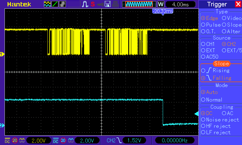
The “convert” instruction (to both sensors)
-
The sensors are individually requested to respond
I’m glad somebody has moved this to a separate topic ![]() but the topic title seems to be prejudging the issue since the OP has not confirmed their setup nor the type of sensor involved!?
but the topic title seems to be prejudging the issue since the OP has not confirmed their setup nor the type of sensor involved!?
I’m not sure what you mean here Robert. A ‘spike’ to me is a very thin (infinitessimally thin?) spike in a graph. Are you saying it has some technical meaning that I and the OP are not aware of?
FWIW, I noticed recently - as the OP of the original thread - that my spikes, which are indeed from a DS18B20, occur specifically when there is a significant power change close to the power supply of the emonTx the sensor is attached to. I have an EV charger that I recently started using, attached to the same CU as the emonTx, and there are spikes when the charger starts up or stops.
OK, I changed it.
To me, a spike is generally an unexplained, most likely false or undesired, short-term condition probably due directly to some variable physical phenomenon. I believe - until proven wrong - that what has been presented can be fully explained, as I have done. The original cause might be something else, but that of which you write is a deliberate, fixed, known, identified value sent by a DS18B20 sensor, and it has a meaning. It is visually presented by emonCMS as a ‘spike’.
If anyone is not interested in being aware that a reading has been missed, an 'If = ’ processing step in emonCMS should be considered.
The latest version of emonLibCM attempts to trap an invalid 85 °C and convert it to the BAD_TEMPERATURE value 30400 (304 °C), as documented.
Thanks all for responses. Much appreciated.
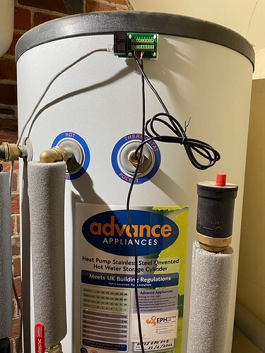
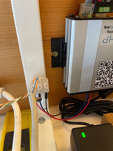
Sensors are DS18B20 wired directly to ‘emonPi / emonTx RJ45 to Terminal Block Breakout for DS18B20’ board. Then ~10m unshielded cat5 to plant room, wired into emonHP.
Admittedly, not the most elegant means of getting into the emonHP, but needs must:
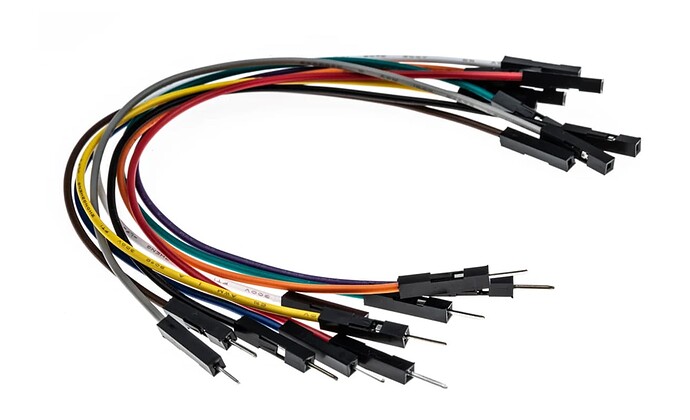
Simply drilled a hole in the backplate of emonHD and ran some RScomponents breadboard jumpers onto the ribbon connector, other side goes to block as shown.
The HeatPump Monitor doesn’t use emonLibCM, so there’s no attempt to trap invalid values decoded from the OneWire bus.
If you read up about the OneWire bus, “star” wiring is not recommended on long cable runs. There’s no clear definition of “long” but I think 10 m is definitely not “short”. What I suggest is first shorten the spur to the top sensor. Best practice is the spur should be as short as possible - a few centimetres, so I suggest do that but still leave enough cable to allow a heavy-handed plumber sufficient room to work.
Also make sure all the joints are good and firm, because 85 °C can be a symptom of an intermittent power supply to the sensors. There’s nothing magical about the RJ45 terminal block, all it does is bring out connector pins to screw sockets wired in parallel, so if the RJ45 IDC plug is suspect (re-crimp it if possible), then you can replace it with a standard screw terminal connector block. (Incidentally, don’t first tin the wires. Solder flows under pressure and the contact pressure is lost over time.)
Not according to the literature: Guidelines for Reliable Long Line 1-Wire Networks | Analog Devices. Star points are only good with short distances to the sensors. Bus “daisy-chain” is the recommended method, with (as I wrote) a minimum length spur off the bus to the intermediate sensors.
It’s all been discussed before:
Ds18b20 and emonTX3CM firmware - post 78 in particular.
I fully expect our antipodean colleague to weigh in before long.
There are other fault modes on the DS18B20 devices, one of the common ones is -127. The most common faults are are, i believe, associated with reading the internal registers. I generally add code to detect either 85 or -127 and ignore it as a bad read and do another read.
The problem is, the code to trap all of those, including of course data transmission errors that result in a failed checksum, doesn’t appear to have been added to the Heat Pump Monitor software, so they make it through to the graph - unless the user is aware of the existence of the various failure modes and traps the values. Even 85 °C could be a valid temperature, but you need to examine all the data available to know if it is or not.
I quite agree and that is why system specifications and user understanding of the system are so important. I have a number of projects using DS18B20’s and I tend to track the reported values as an ongoing average, if I get a value that is out be a predefined value I discard it. As the system designer I have to factor in the probability of it being an erroneous error. In a critical situation I would use a better sensor or dual sensors.
Who me? ;-). You seem to have it covered.
Does anyone know if the emonHP firmware powers down the bus between readings? If it does then I agree it could be an occasional comms failure with the CONVERT command going astray. If not, then it seems more likely to be the bus power is drooping enough to cause the sensor to reset.
I’ve not had any experience with 85C readings, but I run the bus quite differently from the various OEM images, so my experiences are not so relevant to this case. In particular: I never power down the bus, I never issue a broadcast CONVERT command, and immediately after issuing a directed CONVERT command I poll the sensor to ensure that it saw it and has commenced the conversion. If I were to see 85C readings after doing all of that, I’d be pretty confident it’s a bus supply problem.
A few comments on your chocolate block connector:
. it looks like you might be running the power down the twisted pair, you might get better results if you run the signal down the twisted pair, i.e. swap the blue and the orange (with an associated swap at the other end).
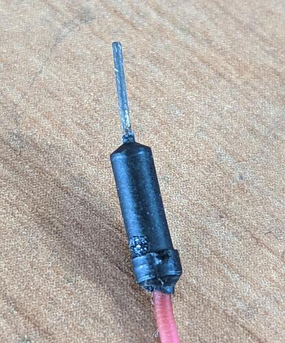
. the pins on my breadboard jumper cables always corrode badly after an extended period (perhaps I live too close to the sea) and that could certainly cause a voltage drop on the bus during conversions. It might be worth inspecting them to make sure they’re nice and shiny.
thanks Bob,
Given that there are already two sensors on the same tank, 40cm apart, and the most extreme temp divergence is unlikely to be much more than 20°C, then it should be easy to code a couple of lines to reject 85°C with durations of single read?
PS it’s not really critical, more of an attempt to accumulate data with a view to improving efficiency and determining next steps in making home more sustainable.
Hi Harley, my comments were not in any way meant to be critical. I have used 18B20 sensors in a horticultural enviroment for a few years and generally they perform well. As you note it is easy to reject obviously wrong values. I buy the stainless steel shealthed ones sourced from China and have had two genuine failures out of about 40 units. In that enviroment I can reject anything above 45°C.
In your case, with an unvented hot water cylinder, it is entirely possible to get a genuine 85°C temperature depending on the heat source.
It looks to me as if we should ask @glyn.hudson or @TrystanLea to put looking at adopting some of the DS18B20 code from emonLibCM into the heat pump monitor on their ‘to do’ list - but I know full well they are very busy with the new Atmel “DB” series of emonTx and emonPi, so it won’t happen any time soon.
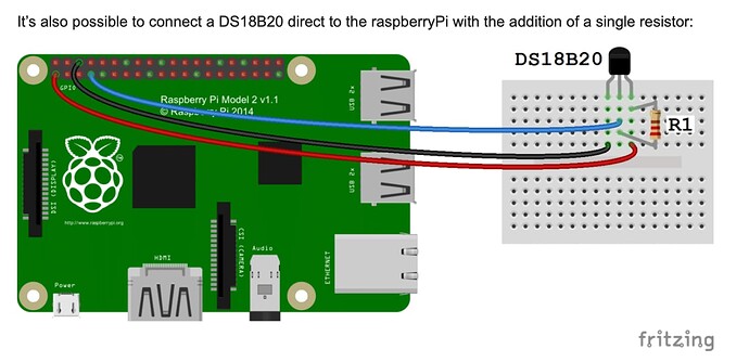
I’m not familiar with the OEM hardware, but why is that necessary? Is there no RJ45 jack to plug into? What’s the ribbon connector you refer to? And I take it from your fitment of an external pull-up there’s not an internal one?
Brian, you need to read up on transmission lines and unterminated stubs - because that’s what is in play here.
[This was in response to an assertion by Brian, later deleted, that a remote star point is fine.]
[Brian suggested in a post later deleted that I needed to understand the user’s problem.]
I understand the user’s problem exactly - he’s getting the occasional bad reading, doesn’t know why and is looking for a solution.
The closer the One-wire bus is to a properly terminated transmission line devoid of reflections, the better it will work and the less chance there is of the data being corrupted. Remember that an 85 °C ‘reading’ is a symptom of the sensor not converting the temperature. We don’t know why this happens, one reason is the command was never sent, the other is it wasn’t received, or it wasn’t received intact, so it got ignored. And one reason the command might have been corrupted was a reflection off the stub.
Just because something the manufacturer recommends you don’t do happens to work for you doesn’t mean it will always work for everybody else. I’m sure they know more about it than you and I put together.
[In another deleted post, Brian continued to assert that star wiring is not fundamentally wrong.]
That which is asserted without proof can equally be dismissed without proof.
Subsequent to those messages being deleted, I’m adding a quote of the first two paragraphs of the introduction to the document I linked in post no.8 above by Maxim/Analog Devices:
Introduction
The 1-Wire protocol was originally designed for communication with nearby devices on a short connection, such as adding auxiliary memory on a single microprocessor port pin. As the use of 1-Wire devices increased, methods were developed to extend the 1-Wire protocol to networked applications well beyond the size of a circuit board. A 1-Wire network is a complex arrangement of 1-Wire devices, communication lines, and connections. Every 1-Wire network is different, often both in topology (layout) and hardware.
A proper match among network components (i.e., master, network cabling, and 1-Wire slave devices, “slaves”) is the precondition for reliable 1-Wire operation. When bus masters are improperly designed or implemented, or when masters intended for short-line use are pressed into service with greatly extended communication lines, then satisfactory performance cannot always be expected.
No, no RJ45 on the emonHD
Sorry, I meant IDC connector. (Old ref to when ribbon cables were used with IDC connectors)
Correct. Earlier thread has details. Glyn provided good solution.
