thanks Bob – certainly not taken/read as criticism. In fact, v helpful.
BTW I’d read and replied in the sense of ‘mission critical’, which my application isn’t particularly!
Still want to get the erroneous 85°C blips resolved and happy to run any experiments that might satisfy intellectual curiosity.
If you really want to ‘kill’ the errant 85 °C reading, pick apart emonLibCM. I don’t mean all of it (!), just the temperature part. It’s in two sections, and there are plenty of subtleties to make it fit and not interfere too much with the continuous monitoring, in all likelihood those will confuse you and they’re not relevant to what you need.
The first part is triggered long enough before the temperatures are needed, and it’s a broadcast request to all sensors to “go and measure”. When they’ve had time to do that - and the power readings have been collected etc, the temperature part is visited again and each sensor in turn is asked to send its reading. This is where the checksum is calculated, the sensor registers are interrogated, and the 85 °C reading is checked.
If you need help, ask. Unfortunately, I’m too tied up with the emonTx V4 to be able to volunteer to do much more.
Gotcha’, thanks for the clarification. So it’s actually RPi DS18B20 code we’re dealing with, not AVR code.
Did you terminate the RJ45 yourself, or butcher an existing ethernet cable? That RJ45 terminal block breakout board chose pins 4 and 5 for 1wire data and GND. That’s a good choice because on a standard ethernet cable those two pins are connected to the one twisted pair (Blue and Blue/White). In your pic above, it looks to me like you run Data and GND down Blue and Orange/White - not a good choice because they don’t form a twisted pair. But unless you built the cable yourself, I don’t see how that could be working at all, so maybe I’m misinterpreting your photo above?
I’m not sure - the drawings show the DS18B20s going to the ATMega. I think the RPi image was just to show the pull-up connected between the data and power lines.
I think so. The breakout at the top is screw terminals, so Harley was free to choose which cores he used for what purpose - and as there’s no guidance published (that I know of) for how to choose the cores in a CAT n cable when it’s not Ethernet, he probably didn’t realise that the signal & ground should be on a twisted pair.
As far as I can tell the EmonHP doesn’t have an AVR in it, although it looks like an earlier version did.
I just had a squiz at how the RPi drives the DS18B20 and it connects 1wire bus power directly to an always-on 3.3V pin… so no attempt to power the bus down (a wise choice in my experience unless of course you’re battery powered). That makes me less inclined to think the 85C is a comms issue, more likely a voltage supply issue on the 1wire bus.
I think all of those cases will only cause an 85C to be returned if the device has just been reset. Once the device has been powered up successfully and at least one good conversion has been completed then I believe each of those failure modes would cause you to re-read the previous conversion - an error that would likely go unnoticed.
Since the RPi doesn’t attempt to manipulate bus power (it’s hardwired to the 3.3V rail) it seems unlikely that a comms failure could cause an 85C to be returned - except in the case where the system has just been powered up.
I’d start by measuring the bus voltage up at the breakout board, ideally with a scope during a conversion, but if that’s not possible, then at least with a multimeter statically.
thanks, I’ll try to borrow a scope for next weekend and take a look at the 3.3V rail before changing the cat5 wiring pairs etc.
just a thought, if there were instability on the 3.3V rail then wouldn’t both sensors re-boot at the same time, as opposed to what we’re seeing which is each sensor glitching at different times?
Interesting question. The re-boot itself is not a problem unless it happens between requesting a conversion and reading the result. If it were to happen after the result was read and before the next conversion was requested it would be benign. You’d need to read the Linux kernel module source code to see exactly how it runs the bus. Does it use global concurrent conversions, or directed conversions? Does it run conversions continuously in the background, or do they get triggered by a user-level process reading the device? etc. etc.
At first blush I’d agree you’d expect them to fail together, but maybe the bus operations and timing are such that it takes out one at a time. It’s hard to say without knowing how the code works. The answers are probably somewhere in here.
As well as the possible software explanation for differences already mentioned, I think there might be a hardware explanation as well. As I understand it the DS18B20 can operate using parasitic power, so it contains some energy storage (presumably a capacitor). Device tolerances might mean that one unit stayed powered up during a brown-out, whilst the other rebooted.
Good point - I just knocked up an experiment to test that on my 53 sensor bus. After the system has been up for a few minutes (so that all sensors had done at least one conversion), I bypass the code that issues the CONVERT command and just leave it running the code that reads the scratchpad. All sensors stick at their latest reading as expected - aiming a hairdryer at them made no difference to the readings.
Then I introduced a s/w controlled bus power failure pulse by shorting Vcc and Data to GND for a s/w controlled interval. Once the power was restored I continued reading all the scratchpad registers. When the power failure was about 400 usecs wide, roughly half the sensors drop out and report 85C while the other half survive and return their old reading. Continued power fail pulses of the same width (every 30 seconds) slowly pick off the survivors until eventually they’re all reporting 85C.
A wider pulse takes out more, and a narrower one fewer, but ~400 μsecs seem to be the sweet spot for dividing them.
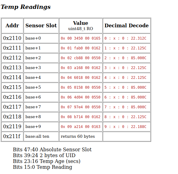
Here’s how the first 10 sensors report after the first power fail pulse:
I haven’t characterised it, but it looks like another area where clones behave differently from genuines. The clones seem to be the earliest to reset back to 85C.