I’ve lost track of the thread, what’s the problem?
I made a new topic to not put too much trash in this one.
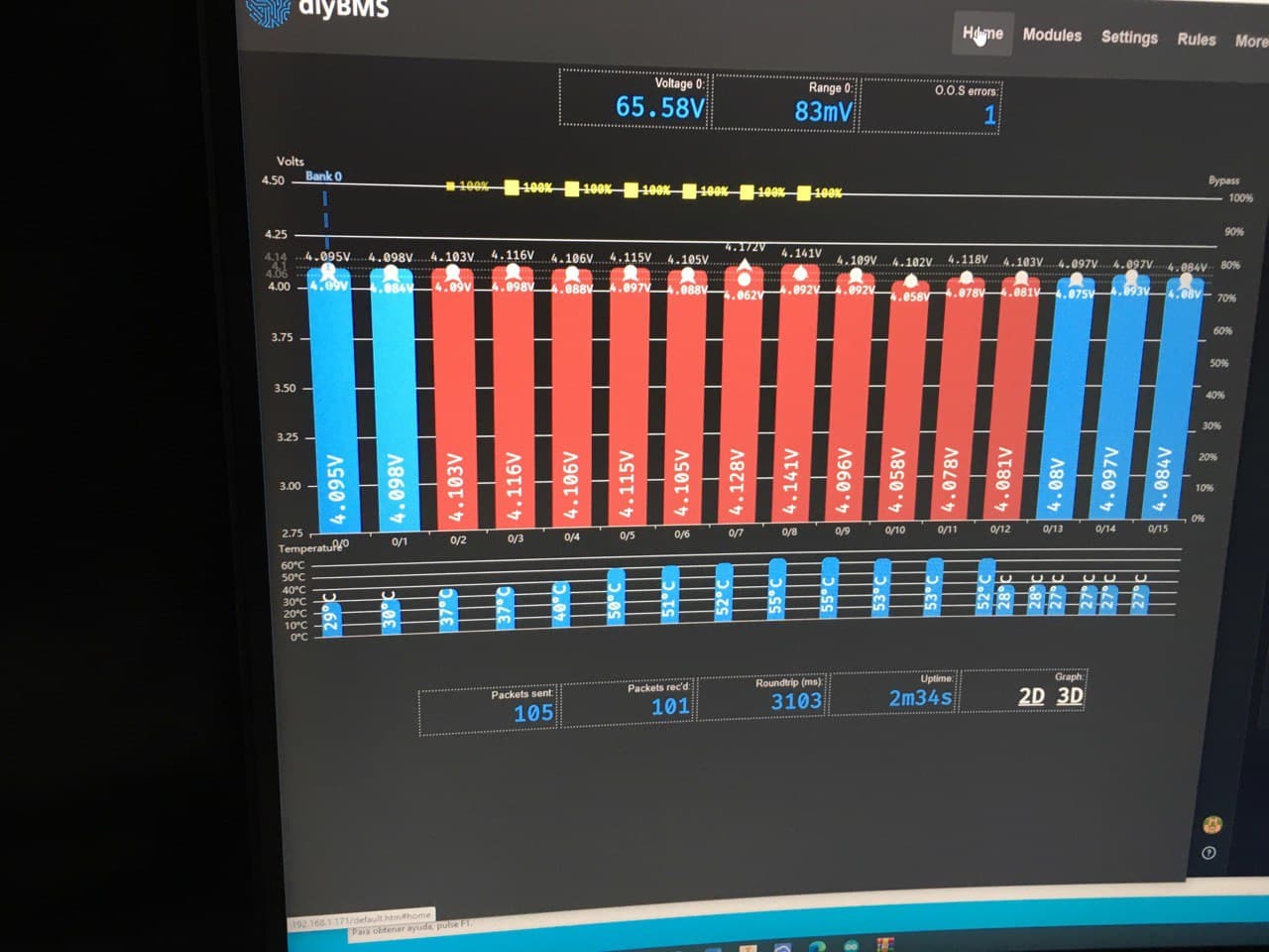
When i charge i used to lose communication, after disconecting the grounds now i see all the 32s modules but one still gets crazy and gives wrong voltages.
If i use the controller with very short cables only on the 12s pack that has the crazy module all works fine.
I think the module does not like the long 5 meter wire from module 8 to module 9.
The osciloscope shows noise but nothing that loses packets or crc errors anymore.
Yes, a 5m cable between modules won’t be great.
The resistance of the cable will likely cause volt drop, and also act as an antenna for noise.
Is it just a bad module? Perhaps a fault voltage reference chip?
the osciloscope was a real eye opener.
Even gounding the cable to the cell negative visually lowered noise by a lot but does not change the voltage fluctuation.
if it was the module fault i think it would also not work with a shorter cable.
but if i have no errors why would the module report wrong voltages?
If packets are lost no message will arrive, but increase the voltage value that the module reads is just strange.
I invite you to see the pictures and video on the topics “Fluctuating voltage when charging” and “workaround-for-the-communication-problems”.
Use 32 cables. As soon as one module starts balancing all 16 begin balancing.
search for „common wire“ here
In the new controller, as you can reset the Wifi, without reloading the firmware and therefore losing the configurations, I have tried changing the data in the SD but it does not connect to the new network.
To change the WiFi settings, use a usb cable connection to the controller and reboot the controller.
Press space bar when prompted to change the WiFi settings.
Thanks Stuart
thanks for the warning, I had not noticed this detail. But if we think that the problem is caused by an increase in the resistance of the common cable, which distorts the value of the next cell, if the section of the cable is large enough to prevent this increase in resistance from causing an erroneous reading in the voltage of the next cell, do you think it could be worth? I was going to order five test plates, but I don’t want to waste my time or money either.
As the maximum current that will flow through this common cable is 2 x 850Ma, I had thought to use cable for 5A (AWG 15 minimum)
Sorry, hsdn‘t tested yet, but I think you can give an online csble calculator a try.
But even if only 20mV drop, it can cause unwanted chain reactions on top level balancing.
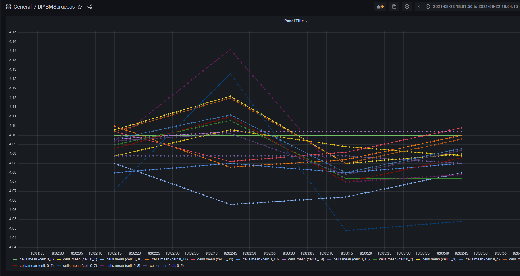
Thanks . I will better do an empirical test. I will monitor all the changes with influx in real time to see the possible reactions in cascade if they happen.
There is no doubt that a 16s system with 32 threads is the best solution, but I want to try reducing the threads to 17. Additionally, once I verify everything is ok, I will add to the experiment, an active balancer to test how they operate together.
The idea is to leave the first balancing section in the hands of the active balancer (eg in Lifepo4 cells) up to 3.3v and maintain the balance with both DIYBMS and active balancer between 3.3v and 3.45V-3.50v since I have not yet determined how much. I will charge.
DIYBMS will provide detailed monitoring of the experience through Influx.
Despite using thick cables, I have been able to verify the cascade effect, a cell starts to unload and is dragging the previous ones. It is a short time, but if it is an unwanted effect that originates in the fact that the same cable is negative for one cell and positive for the next, therefore, discarded the option, Thank you very much
another matter .
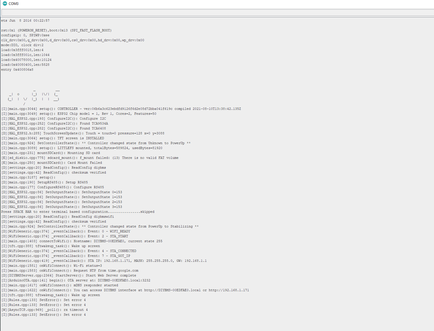
Stuart I have prepared another new controller, it does not have the TJA1057gt / 3.
In principle it works well but has a peculiarity. It starts up but the screen remains blank, check that at this point if it entered with a serial monitor through the port, the boot cycle would be activated and it went to a complete state, showing data on the screen, etc. Then I have also verified that the same effect is obtained by pressing the RST button of the Esp32.
That is, I start the controller, the screen remains completely white but if I press RST then it restarts and the screen image appears. Does it happen to you what may be causing this dysfunction?
Does it work with the screen disconnected?
I’ve had another report of something similar, the code hasn’t changed for the TFT screen for a long time.
Perhaps the PCB layout on the TFT is different?
checking the http://jlcpcb.com/ for 2 weeks already and can’t order a board, lots of components out of stock,how do you guys get your boards, that’s just crazy 
I don’t at the moment, had no luck since April!
there is a way to backorder parts, but for some of them you need to buy like 4000 pcs Should we start group order?
@stuart : I know this is probably somewhere in the huge thread above, but I will just ask here,
I need to program a new weemos as the magic smoke escaped my old one as well from the inverter.
So I v4.21 boards, the latest diyBMSv4Code still compatible ?
Thanks inadvance