Which specific boards are you looking for? I have a handful of extra module boards (v4.0 or v4.1 IIRC) but no spare esp32 controller boards.
I need the whole lot. 14 BMS boards, Shunt, Controller, etc. And the newest versions of everything.
I’m building a 100P14S battery bank for a Tiny Home Prototype Project, 48v system, using 18650’s (2200mAh). FYI, I’m also adding a Sol-Ark system to manage the whole thing - 12K or 5K, I haven’t decided yet - just so you know the big picture.
I checked what I have of extras and I can only help with the BMS module boards, I have 14 v4.1 module boards (7 fully assembled and I have the parts for the remaining). I don’t have any spare controller PCBs or any of the shunt PCBs.
Unfortunately with the parts shortages it is going to be a challenge to find all of the latest PCBs. I was going to order a batch of the Shunt PCBs but with multiple components being unavailable I’ve held off on ordering.
Sounds like an interesting project. I’m currently working with 160p7s (24v, ~20kWh) and have enough 18650s on hand to double the capacity.
Very cool. Do you have any plans to post videos or a (progress) blog about your project?
Wow, I didn’t think the chip shortages was effecting PCB production, but I guess everything that goes on or with them is going to be caught up in all the shortages.
Can you email or call me directly so we can discuss timeline and costs for the 14 BMS modules as well as when you think a controller with screen will be likely?
Thanks
Not at this time. This is mostly just a backup supply for when PG&E decides that a PSPS event is necessary (PSPS = Public Safety Power Shutoff). The longest PSPS event we have seen was around 36hrs and it was a mess (not necessarily for us but the area in general). I’d rather not have a generator since I don’t have a good place to store it when not needed. So I now have a semi-portable setup that I can use as-needed.
PCBs are not generally impacted but being able to populate them is impacted. JLCPCB usually has most parts for the PCBs BUT often there are a few that are unavailable (ATTiny841-SSU as example).
Right now I’m not planning on ordering more PCBs unless there is enough demand for them. The costs will scale better for a full order (30 PCBs). If there is enough demand for a batch I can do some further digging into the BOM and see what parts may be unavailable etc.
Thanks. Please keep me posted if you see any changes coming.
I’m also seeing a lot of fluctuating voltages when charging or discharging. One cell could be the higher on the bank and 10s later it’s the lowest. Looking at the graph it seems like seeing sea waves.
I wonder if that’s normal.
If absorbtion is set to 55,3 and float to 55v, what do you think bypass should be set?
Are you using common cabling or has each cell its individual cable to + and - ?
And how is the power source to your controller?
And what inverter?
We had lot of problems with victron system when the powersupply of the controller was a cheap DCDC.
For a test use a Powerbank to power the controller.
Thanks dakoal.
If you refer to the battery series, this is a 18650 custom battery. With busbars on each side of series.
The modules are connected individually to those busbars.
I have Victron equipment and the power source is a AC PSU (5A iirc)
I could try with a power bank add you suggested.
just plug it into usb of cerbo gx, if you have one…
Karl is right, USB Port of cerbo is a good choice.
Victron does some dirty pulsing on DC side if the Battery is to small we saw on the oscilloscope. We were playing around with DC Filters and more to get rid of this.
Even with low amps we saw this on small Ah batteries. If you are expanding your Ah it should get better.
Also look into the victron guide for busbars:
(cabling guide or so is the name)
check that the position is well balanced on the copper if you have more than one battery/multiplus.
meaning for example not all battery lugs on the left and all multis on the right side.
And the last: cable length.
shorter is not always better
search on victron site for „DC RIPPLE“
so thats enough for one post.
One note.
Years ago I built some 18650 battery packs.
One 12kWh with 14 x 120P Blocks and a 24kWh, 2 banks with each 14 x 120P.
Using a 16mm2 Cabling to the Busbar that was a 300mm2 Copper plate.
Attached was a 3kW custom built inverter/charger on the 24 kWh and a victron Multiplus II 3kW on the 12kWh battery.
But I can‘t say if the jumping values are there, because one has a batrium and the other has a china BMS.
I also get a DC RIPPLE so bad that it can jump drom 3.8 to 4.5v and balancing kicks in but only when i use long comunication cables, when short cables the voltage only jumps 9mv.
Looks good, but how does the heat on balancing is transported away?
I think you plug the modules upside down onto your PCB, is this correct?
If yes, the heat is locked between module and your PCB.
And I can‘t see if you use common wiring or direct 1:1 (every module has its own direct connection/cable +/- to the single cell)
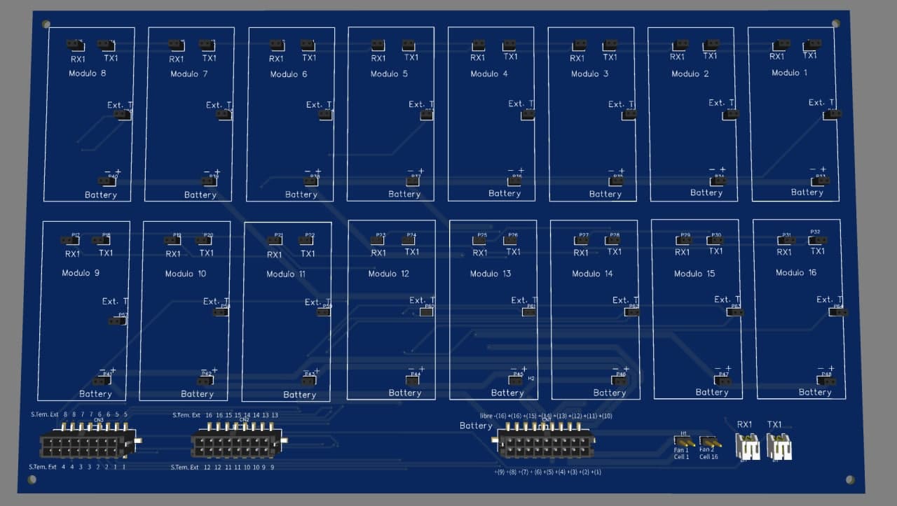
This board is in its initial design phase.
The modules are placed with the resistors facing the outside, the idea is to add a system of fans to cool it, in fact the reason for integrating the 16 modules together is to facilitate the cooling of said modules.
The battery connections are made with 17 cables, the union of a battery with the previous, negative with positive, is used so that each cable that reaches the board, serves as a negative of one cell and positive of the next
when will we be able to use rx2 and tx2?
I won’t be using those, they have been removed from the most recent PCB design.
ok, could be the solution for my problem i guess i’ll try to use 2 controllers at the same time then.