While my PCBs are not here yet, i have installed the firmware to the controller (Wemos D1 mini) and while the router see the DIY BMS controller (after given the user and password from the internet at 192.168.4.1), i can not log in yet with his ip adres shown in the router. Is it really necesary to have it plugged in in the controller to be able to log in??![]()
Hello from newbie,
First of all i would like to say thank you for such a great project which makes me excited. İ have completed payment jlcpcb 30 v4.2 modules and 5 controller. İ programmed controller and it works fine but due to pandemic i couldn’t get usbasp programmers for modules. İs there any change to program modules over d1 mini? Or any other advise? İ searched over internet but may be unlucky couldn’t find.
Thanks for all.
You could try programming an arduino, I’m not sure it can be done but you can investigate it, surely there is a lot of literature about it on the net I located this
1 Like
Hi all, I have since the beginning of 2020 the DIYBMS v4 in use, which was the first version that could be assembled via JLCPCB. In March I have loaded the controller with version 4.2, so I still have the white GUI. Now I wanted to update the controller. Do I have to update the boards as well?
By the way, the BMS runs like a charm, thanks again Stuart for the development 
Yes, the latest code is a major change, so both module boards and controller need upgrading. The instructions are in GITHUB.
1 Like
I’ve just launched a new version of the modules boards - v4.40
Heres a video all about them…

2 Likes
The idea of the included temperature module but that can be separated has seemed brilliant to me. I see that you have changed it to a 10k thermistor that is very easy to obtain and much cheaper than the 47K ohm ones, which I acquired for 4.21. I have already ordered the first 20 to test them. What discharge capacity does the 4.40 850mAh have as the 4.21 or does it have a little more?
CHIP RESISTOR - SURFACE MOUNT 3.3OHMS ±1% 3/4W 1210 ROHS,
4 in series with 4 in parallel gives 3.30 Ohm equivalent resistance
16 resistors provide 16*0.75W=12W of power disipation.
Balance current:
- 1.27A at 4.2V and 5.35W power
- 1.21A at 4.0V and 4.84W power
- 1.13A at 3.75V and 4.26W power
I still have 2 controllers and 14 modules over. Only the ATTINY 841 is missing from the modules.
If someone still needs some, I could give them away cheaply.
I wanted to build 2 power banks, but then decided to only use one.
I am from Germany.
SOLD / Verkauft !
U are from ?
Germany
I’ll write that in my first post again, sorry I forgot
U want to sale all ?
yes, i don’t need the parts anymore
pm send
Here’s a tip if you choose to hand solder your boards:
Using solder paste, heat up the boards first, then quickly dab the solder where you want it. Once the boards cool down, you can place your components where they go. (They kind of stick in place)
1 Like
HI.
Version 4.4 is very cool.
But for Version 4.41 I have a request for enhancement.
The power plug you use is still PH2.0 but the balance power increased.
Even with the 4.21 modules doing less current we see a big voltage drop on balancing, with higher current now it will be even bigger.
A XH Connector for example (with 2.5 mm pin distance) can be equipped with much thicker cables and will fit for the current better.
Or a solution with 4 holes (for both plugs ph 2.0 and xh 2.5) will also work I think.
Are you running the latest code? The latest code provides a much more stable voltage reading when balancing is running.
What cells are you using? Maybe my design for 272Ah lishen cells is also sutible for you:
They have an balancing current of 2.6A
We are a large group of people in Spain who are making our own batteries with prismatic cells LISHEN272 and CATL 310.
We loved your Fork, I even tried to order one in Jclpcb but I found a lack of supply of some component, the resistors I think.
I will upload to the telegram that we use your link. and what has been said if you would like to share the gerber and the bom, etc. It would be great to order some to try.
I still have a little doubt about the separation between terminals of the CATL 310 I am behind the Chinese who are going to supply them to us to have exact measurements.
We are in touch .
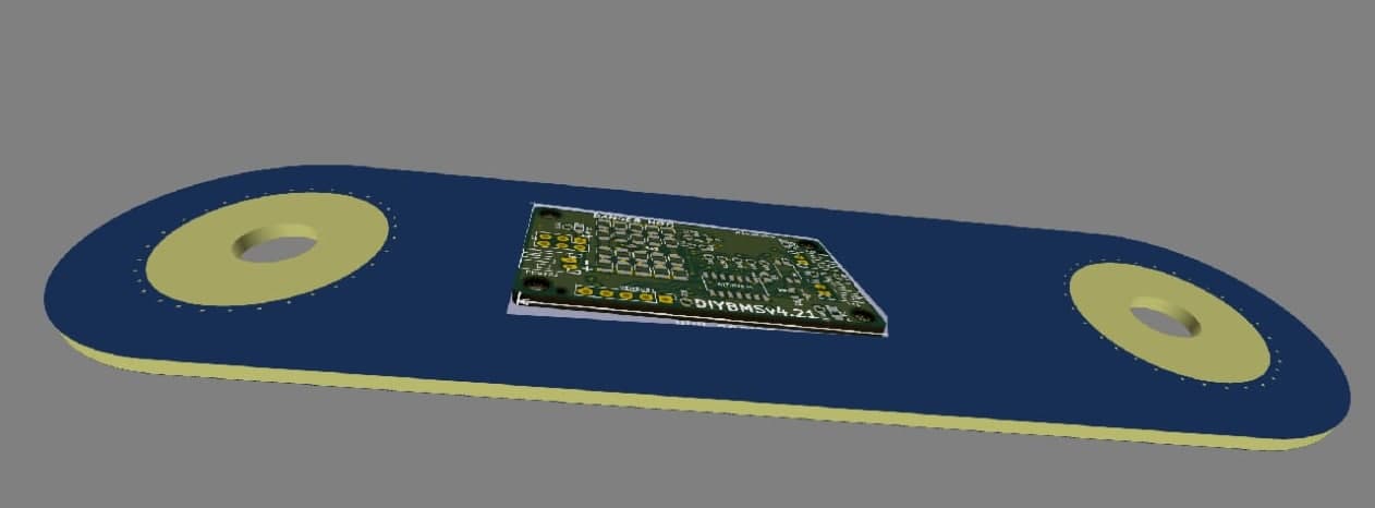
Fabien, another thing that we comment is that it would be great to make a plate only with the battery terminals and connection to the V4.21 modules that we already have many of us, it would be a plate in which a V4.21 module is connected with two pins its connections to battery with a plate that is placed on the Lishen. It is a way to reuse the modules you already have for prismatic cels. I made a sketch.
Hi George, nice job!! Where can I find wiring diagram of 2 and 4 jst connectors? I’ve been trying to make modules work without success, I would like to double check I’m connecting all properly. Just tested the controller with standard modules and worked out. Thanks in advance