DIYBMS for Lithium Iron Phosphate battery cells (LiFePo4) 280aH

Hey David,

Yesterday i checked my design. Bad news, something is not working. Now its time to figuring out what the problem is. First problem is that the footprint for the opto is wrong. It is to small and i didn’t properly check it during layouting.

Flashing works but no communication. I will keep you updated.

Normal all part numbers should match with LSCS parts beside of the Voltage reference diode.

My Lishen cells also arrived yesterday after only 24 Working days. Ordered from Basen. As soon as the PCB is working i will check them with teh cells.

So, i already know that i flipped the footprints of the green and red LED and the connectors. I had to re-solder the LEDs and mounted the connectors of the com cables to the bottom. But i still have a problem because the modules don’t want to communicate with the controller. Tomorrow i will get my oszi and check the signals.

I did order the normal circuit as well in case there were issues with this new design. Also had to adjust a few things on the board that EasyEDA was complaining about… but don’t think it complained about those items…

My main issue was that in my test setup i used an old ESP with a firmware from February of 2020. Since then Stuard changed the communication protocol of the Controller. That did drive me crazy the last two days until i figured that out.

JLC didn’t complain anything with my order. What did they complain to you and what did you change?

There are more or less 4 Problems with the v0.1 of my board:

  1. The LED’s are flipped → turn the LED around and resolder them

  2. The TX/RX connectors are flipped → mount the first and last TX/RX of the chain on the bottom of the PCB

  3. The R22 shouldn’t be soldered to the board. → desolder these

  4. The Opto has the wrong footprint → squeeze legs together and resolder

The board is also based on the V4.0 design not on the V4.21 as mentioned on the Silkscreen.

I already fixed the known issues and also changed the board design to the newest 4.21 design from Stuard.

The GS Voltage of the Mosfet is 60mV at 2.6A current → 23mOhm Ron → Pmos = ~160mW what should be totally fine for this model.

1 Like

Jau, thank you for all of your work on this version! I have 64 50Ah lifepo4 cells in 16s 4p configuration, so the wiring would get quite messy if I used the original boards. I believe my cell terminals are a little closer together than 90mm, but need to confirm. Looking forward to your and David’s continued testing!


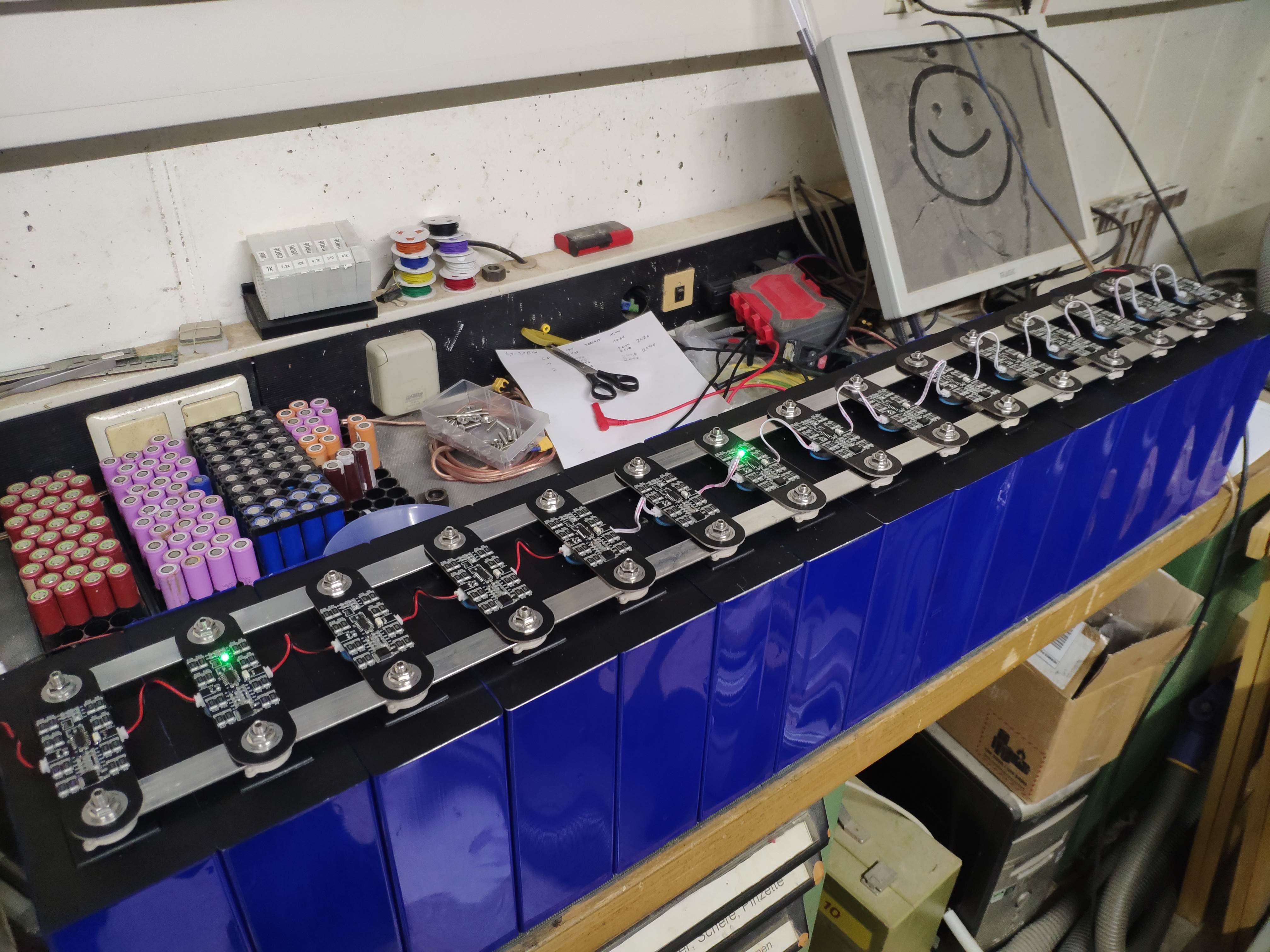
First 15 modules are working. Looking nice and clean.
If there is enough interest i could adjust the design for other spacing. Way smaller than ~80mm bolt spacing will be a problem because of the space for the traces and parts.

Still need to test the external temp sensor header, waiting for the parts to arrive.

3 Likes

Nice job! My terminal spacing is only 67mm, so I speculate the pcb will require significant modification. Are the OSH files your most recent version? If so, I’ll use them as a starting point.

https://easyeda.com/SKOJau/diybms_v4-2_lishen

Is the current most updated version. It is not tested because i changed the design to stuards V4.21.
Normally there should be everything OK because the known problems are already fixed at that design.
As soon as the new controller version is released by Stuard i will also order and test my new design.
Yeah, you need to change some parts with only the 67mm spacing. I would recommend to change all parts from 0806 to 0604 and also reduce the power resistors from 16 to only 8 for a 1.3A balancing current. Should be more than enough for 50Ah cells and if you are not cooling them with an extra heatsink they will reach 60°C very fast anyway.

1 Like

Stuart has published the new controller on GitHub.

I’m still waiting for my boards to arrive but I did not make significant changes… I did replace the one temp sensor resistor. Will update when I have something new as well but guessing will have to make the changes Jau already had to :slight_smile:

@Billy_Boes These technically should work with the new controller board as well… the “circuit” boards attached to the cells themselves are supposed to be the same for either controller board.

yeah, saw it yesterday. Will order some for my projects.
Still have to finish two other PCB projects and than i will order and test the v4.21 boards.

wow, this is awesome! I can’t believe that someone finally made this. Is it ready to go now? like no more flipping leds or bending opto leads etc?

Add one more interested party. I too have the Lishen 272Ah cells (64 of them.). I am hoping to get one of the new controller boards atanisoft is preparing for those in NA area. Adding these would make the project that much easier.

The actual design should work. But i want to update it to the new V4.4 soon and also make a second design because the communication connector is on the wrong side for every second battery.I planed to make a PCB with two mirrored designs with a break point. That will make the assembly by jlc way cheaper.

If anyone else has an idea how to arrange the com ports that they work for both orientations let me know.

Looking at the 4.4 design with the break for the external temp sensor…
I’ve used the external sensor on other battery packs but I’m assuming with the prismatic cells you just want the sensor on board near a terminal? So is another sensor required? Or put a sensor at each end?
Is there any reason not to make an odd and even board with the com ports swapped?

Hy,
I´m not familiar with PCB generation but I like the Idea from a Adapter PCB to stick Stuart´s v4.4 Module on a LiFePo4 Prismatic cell.
I made a example of what I think about … the Adapter can turn for + and - so that the Original v4.4 is always at same orientation.
Maybe it´s possible to contact also “Ext. Temp” to the Adapter ?

Can anyone generate that PCB´s Gerber Files ?

I thought one advantage of boards specific to this cell size was the ability to use larger resistors for greater balance current for these now up to 310Ah cells? The odd/even board idea means you could also add heatsinks on top. Is balance current not an issue?

1 Like

I think the problem will be that at least JLC will not plate the slotted holes because they will mfg them after the plating process.
I could make a gerber for that if you send me the step for your design. Hopefully i will find time to spend for the project this weekend.

The first design is running since 2 weeks on my test battery without any problems.

The specific design with odd and even is because it looks more tidied up.
I have to build at least 10 packs á 15 cells for me and some friends so they should at least look nice :slight_smile:

Jau, duplicating & moving the Rx/Tx connections to the ‘corners’ of the board is one solution. Traces are criss-crossed, so Rx pins are in the same place regardless of board orientation. Here’s a concept:

2 Likes